Ronetix EB9261 User manual

EB9261
Evaluation Board
User Manual
Version 1.2
embedded development tools

Acknowledgements
EB9261 User’s manual www.ronetix.at
2
November, 2008
Ronetix has made every attempt to ensure that the information in this document is accurate and
complete. However, Ronetix assumes no responsibility for any errors, omissions, or for any
consequences resulting from the use of the information included herein or the equipment it
accompanies. Ronetix reserves the right to make changes in its products and specifications at any
time without notice.
Any software described in this document is furnished under a license or non-disclosure agreement.
It is against the law to copy this software on magnetic tape, disk, or other medium for any purpose
other than the licensee's personal use.
Ronetix GmbH
Waidhausenstrasse 13/5
1140 Vienna
Austria
Tel: +43-1-236 1101
Fax: +43-1- 8174 955 3464
Internet: www.ronetix.at
E-Mail info@ronetix.at
Acknowledgments:
ARM, ARM7, ARM9 and Thumb are trademarks of ARM Ltd.
Windows, Win32, Windows CE are trademarks of Microsoft Corporation.
All other trademarks are trademarks of their respective companies.
© 2005-2010 RONETIX
All rights reserved.

Contents
EB9261 User’s manual www.ronetix.at
3
1
OVERVIEW...........................................................................................................................4
1.1
Scope ...............................................................................................................................4
1.2
Package contents ...........................................................................................................4
2
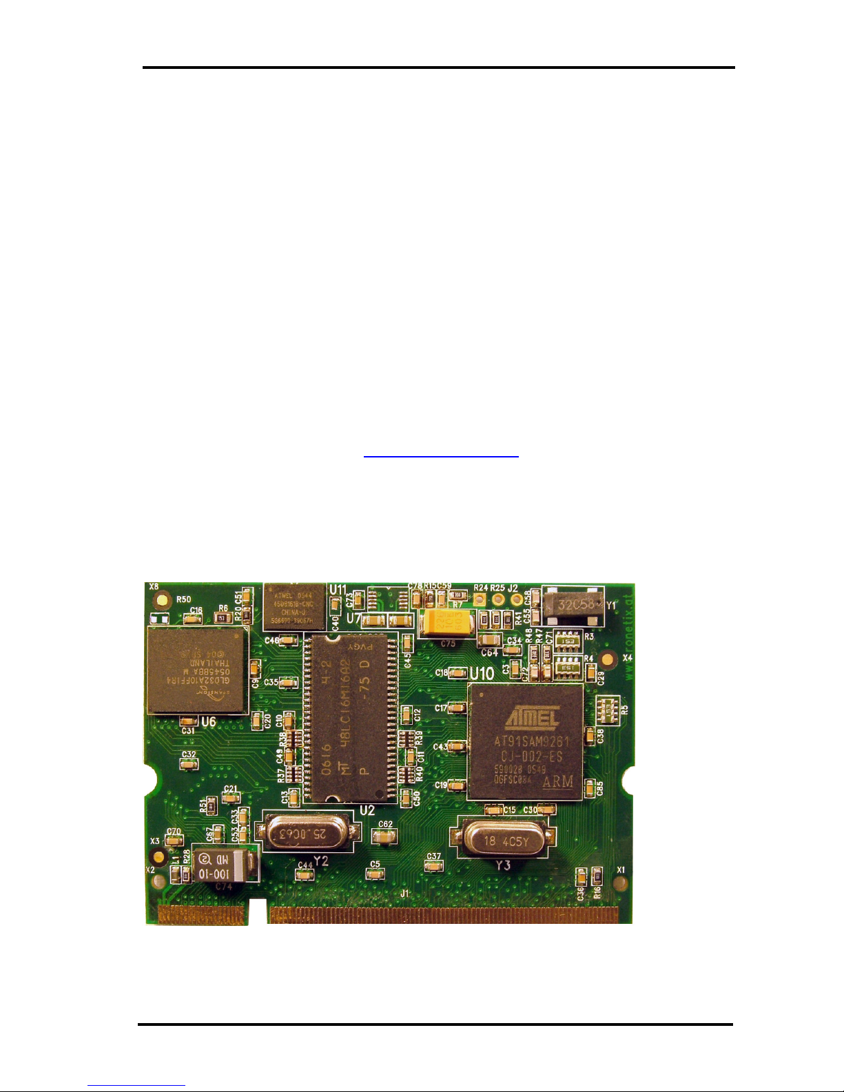
THE CPU MODULE PM9261 ...............................................................................................4
2.1
The PM9261 .....................................................................................................................4
2.2
Electrostatic Warning.....................................................................................................5
2.3
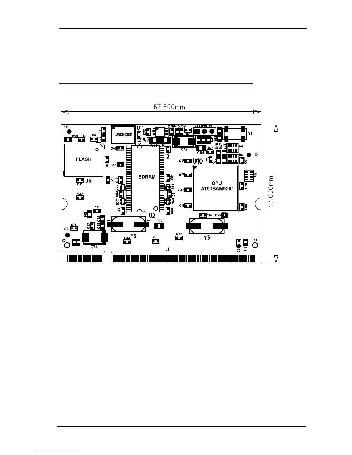
Layout ..............................................................................................................................6
2.4
Circuit Description .........................................................................................................7
2.4.1
AT91SAM9261 .............................................................................................................7
2.4.2
200-pin SODIMM Connector ........................................................................................7
2.4.3
Memories......................................................................................................................7
2.4.4
Serial Number Chip DS2401........................................................................................8
2.4.5
Crystal Quartzes...........................................................................................................8
2.4.6
Power ...........................................................................................................................8
2.4.7
Ethernet Controller .......................................................................................................8
2.4.8
Temperature range.......................................................................................................8
3
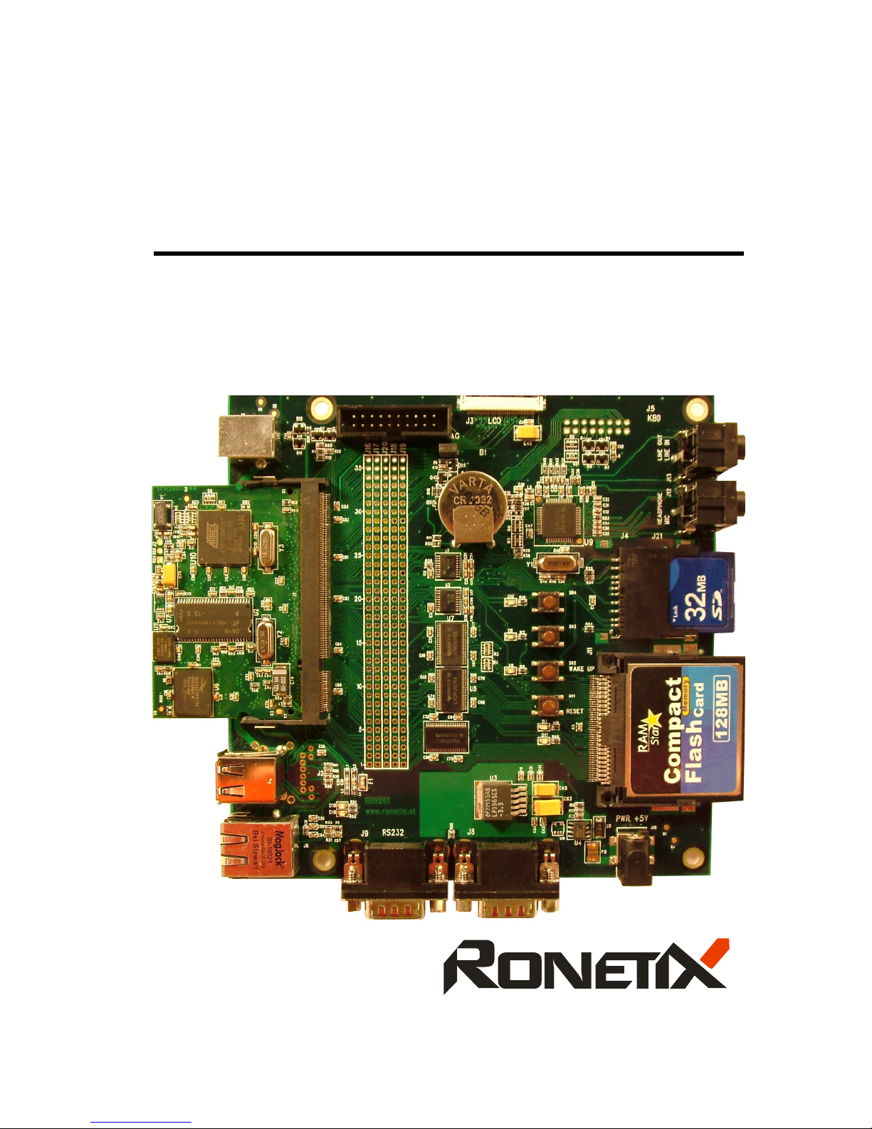
BASE BOARD BB9261........................................................................................................9
3.1
Revisions.......................................................................................................................10
3.2
Jumpers.........................................................................................................................10
3.3
Electrostatic Warning...................................................................................................10
3.4
Requirements................................................................................................................11
4
GETTING STARTED ..........................................................................................................11
4.1
Getting started with Linux ...........................................................................................11
4.2
Getting started with a standalone example under Windows ...................................11

EB9261
EB9261 User’s manual www.ronetix.at
4
1 Overview
1.1 Scope
The EB9261 Development Kit enables real time code development and evaluation. It supports
AT91SAM9261.
1.2 Package contents
The Development Kit consists of:
- CPU Module PM9261
- Base Board BB9261
- Power Supply 5V/1A
- PEEDI – JTAG Emulator and Flash Programmer (optional)
- DVD including software, datasheets and documentation
A copy of the DVD can be found here: http://download.ronetix.info
2 The CPU Module PM9261
2.1 The PM9261
The PM9261 from Ronetix consists of an AT91SAM9261 together with several peripherals:
►ATMEL AT91SAM9261 Microcontroller in BGA217 package with:

EB9261
EB9261 User’s manual www.ronetix.at
5
ARM926EJ-S™ ARM
®
Processor
DSP Instruction Extensions
ARM Jazelle
®
Technology for Java
®
Acceleration
16 Kbytes Data Cache, 16 Kbytes Instruction Cache, Write Buffer
210 MIPS at 190 MHz
Bus Matrix – Five Masters and Five Slaves
Embedded ICE (In-Circuit Emulation) with JTAG interface
160 Kbytes Internal RAM
3 USARTs
3 Synchronous Serial Controllers (SSC)
Two Master/Slave SPI Interfaces
One 3-Channel 16-bit Timer/Counter
Programmable Watchdog Timer
USB 2.0 Full Speed (12 Mbits/s) – Host Port
USB 2.0 Full Speed (12 Mbits/s) – Device Port
LCD Controller
Real-time Clock with On-chip 32 kHz Oscillator
96 Programmable I/O Lines
Advanced Power Management Controller
►4 Mbyte 16-bit Flash
►64 Mbyte 32-bit SDRAM
►2 Gbit NAND Flash, 16-bit
►16 Mbits SPI Serial DataFlash AT45DB161B
►32 Kbytes SPI Serial EEPROM AT25256A
►Serial Number Chip DS2401
►SODIMM 200-pin connector
►Dimension 67,6 mm x 47.0 mm
2.2 Electrostatic Warning
The PM9261 Module is shipped in protective anti-static packaging. The board must not be subjected to
high electrostatic potentials. A grounding strap or similar protective device should be worn when
handling the board. Avoid touching the component pins or any other metallic element.

EB9261
EB9261 User’s manual www.ronetix.at
6
2.3 Layout
The board layout diagram (Figure 2-1 and Figure 2-2) shows an approximate floorplan of the board. It
was designed to provide the smallest board dimensions. The board has 4 signal layers and 2 power
planes. The mechanical drawing of the CPU module is available on the DVD or here:
http://download.ronetix.info/boards/doc/PM9261/v1.2/bb9261_v1.2_assembly.pdf
Figure 2-1 – Top View
Figure 2-2 – Bottom View

EB9261
EB9261 User’s manual www.ronetix.at
7
2.4 Circuit Description
The schematic of the CPU module can be found on the DVD or here:
http://download.ronetix.info/boards/doc/PM9261/v1.2/bb9261_v1.2_sch.pdf
2.4.1 AT91SAM9261
The footprint is for a 217-pin BGA package.
The pull-down resistor R42 enables to choose between the standard ICE debug mode and the JTAG
boundary scan mode of operation.
The R42 is assembled by default – ICE debug mode.
2.4.2 200-pin SODIMM Connector
The 200-pin SODIMM connector makes the most CPU pins, Vcc 3.3V and Ground available to the
user.
The recommended SODIMM200 2.5V connector is:
FCI
59354-052FSLF
The description of the SODIM200 signals is available on the DVD or:
http://download.ronetix.info/boards/doc/PM9263/SODIMM200_PM9261_PM9263.xls
2.4.3 Memories
The PM9261 has on board:
•4 Mbyte, 16-bit Parallel Flash (boot capable)
•64 Mbyte, 32-bit SDRAM
•2 Gbit, 8 or 16-bit NAND Flash (boot capable)
•32 Mbit, serial SPI DataFlash (boot capable)

EB9261
EB9261 User’s manual www.ronetix.at
8
•32 Kbytes serial SPI Serial EEPROM AT25256A (optional)
The AT91SAM9261 CPU can boot in 2 different ways:
- If BMS = 0 (J22 closed) - direct from the parallel Flash
- If BMS = 1 (J22 open) – then the internal 32 KB ROM boot loader of AT91SAM9261 allows the
CPU to boot from the DataFlash or the NAND Flash
The JTAG Emulator and Flash Programmer PEEDI from Ronetix support the flash programming of all
these memories: FLASH, DataFlash and NAND Flash.
For more information visit http://www.ronetix.at/peedi.html
2.4.4 Serial Number Chip DS2401
The DS2401 1-Wire® Silicon Serial Number has a unique 48-bit serial number, an 8-bit CRC, and an
8-bit Family Code. It is connected to PA7 of the AT91SAM9261 and allows the module to have a
unique serial number. It can be used also for the MAC address of the Ethernet controller.
2.4.5 Crystal Quartzes
The board has three crystals: a 32.768 kHz connected to the RTC low-power oscillator of the
AT91SAM9261, an 18.4320 MHz connected to the main oscillator and a 25 MHz for the Ethernet
Controller.
The AT91SAM9261 Master Clock can be derived from the 32.768 kHz crystal quartz or the 18.4320
MHz crystal quartz depending on the programming of the APMC registers.
2.4.6 Power
PM9261 requires only 3.3V power supply. Pin 200 of the SODIMM200 connector is connected to +5V
on the base board, but for custom designs this is not necessary – pin 200 can be connected to +3.3V.
The power consumption of PM9263 with all peripherals is 110mA/3.3V.
2.4.7 Ethernet Controller
The PM9261 has on board a DM9000A Fast Ethernet Controller with 10/100M PHY and 16 Kbytes
SRAM.
2.4.8 Temperature range
PM9261 is available in two temperature ranges:
- Standard temperature range 0°+70°C
- Industrial temperature range -40°+85°C

EB9261
EB9261 User’s manual www.ronetix.at
9
3 Base Board BB9261
The BB9261is equipped with:
- SODIMM 200 pin for reception of PM9261
- One USB device port
- Two USB Host ports
- One RJ45 10/100M Ethernet
- JTAG debug interface, 20-pin
- One 3.5” ¼ VGA TFT LCD + Touch Screen – 40 pin
- Two RS232
- Four Audio connectors: Line In, Line Out, Headphone, Microphone
- One MMC/SD card

EB9261
EB9261 User’s manual www.ronetix.at
10
- One Compact Flash connector.
- Expansion connectors
- One reset push-button
- One wakeup push-button
- Two user input push-buttons
- Three general purpose LEDs
- Two power LEDs: one for 5V and one for 3.3V
- One Lithium Coin Battery
- DC power connector 2.1mm by 5.5mm. The central pin is positive polarity.
The board dimension is 145 mm by 145 mm
3.1 Revisions
There are two revisions of the BB9261: v1.1 and v1.2.
The differences between both versions are:
- The CompactFlash connector on v1.1 is not soldered because of a hardware design mistake.
On v1.2 the CompactFlash connector is soldered.
- Added 3.3K pull-up to PA1 (MMC: CMD/SI)
- Added MMC Write Protect: PB5
- Added MMC Card Detect: PA21
3.2 Jumpers
Jumper Description
J14
Forces power on. To use the software shutdown control, J20 must be opened and the
battery backup J23 must be closed.
default: close
J22
Boot mode select:
open – the CPU boots from the internal ROM
close – the CPU boots from the NOR Flash
default: close
J23 Connect/Disconnect the 3.0V battery backup.
default: open
3.3 Electrostatic Warning
The BB9261 Module is shipped in protective anti-static packaging. The board must not be subjected to
high electrostatic potentials. A grounding strap or similar protective device should be worn when
handling the board. Avoid touching the component pins or any other metallic element.

EB9261
EB9261 User’s manual www.ronetix.at
11
3.4 Requirements
The BB9261 requires DC power supply 5V / 1A. The DC power connector is 2.1mm by 5.5mm; the
central pin is positive polarity.
The board has reverse voltage protection.
For more information please see the board schematics on the DVD.
4 Getting started
The EB9261 is delivered with a DVD containing all necessary and step-by-step procedure for working
with the GNU development tools.
Please refer to this DVD, or to the Ronetix web site, for the most up-to-date information:
http://download.ronetix.info
4.1 Getting started with Linux
To get started with U-BOOT and Linux, please read the U-BOOT and Linux Kernel readme from the
DVD or from here:
http://download.ronetix.info/boards
4.2 Getting started with a standalone example under Windows
To get started with a standalone example under Windows, please read the “Software Installation
Guide” from the DVD or from here:
http://download.ronetix.info/boards
Table of contents