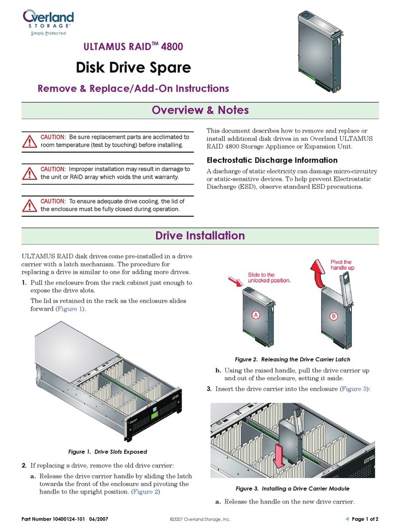
Helmer PC900 User manual

C
Platelet Storage System Manual
Models PC900, PC1200
Version N
English
HELMER LABS, INC. 15425 HERRIMAN BLVD., NOBLESVILLE, IN 46060 USA
PHONE (317) 773-9073 FAX (317) 773-9082
USA and CANADA
1-800-743-5637

11-360003/J
Operation Manual
Page
Installation……………………………………………………………… 2
Controls and Components……………………………………………... 3
Temperature and Alarm Systems……………………………………... 4
A. Digital Temperature Controller
B. Accessing the Chamber Set Temperature
C. Accessing the Low and High Alarm Programs
D. Alarm Timer Delay
E. Power Failure Alarm
Quality Control…………………………...……………………………………… 6
A. Calibration of the Digital Controller
B. Alarm System Test
Specifications……………………………………………………………
Description of Symbols ………….……………………………………
Maintenance…………………………………………………………….
Cleaning…………………………………………………………………
Troubleshooting………………………………………………………..
Warranty………………………………………………………………...
8
8
8
9
10
13
Appendix (Figures, List of European distributors where applicable)
- Labeling………………………………………………………….. 2

21-360003/J
Installation
1) Carefully unpack your Helmer Platelet Incubator.
2) Select a location keeping the following in mind:
1) Allow 4 inches (10 cm) of air space above and at the back of the unit for adequate air
circulation. Do not push the unit tight against a back wall.
2) Use a grounded outlet with adequate power specifications as listed on the
specifications label on the back of the unit.
3) Keep away from direct sunlight or high temperature areas.
3) Turn the power switch to "I" (ON) and allow the chamber temperature to stabilize (30
minutes) at the factory preset controller values. While waiting for the chamber temperature
to stabilize, carefully continue reading through the instruction manual.
4) Open the door to the chart recorder and connect the leads to the 9 volt battery.
5) Insert an approved, calibrated thermometer on the top shelf of your flatbed platelet agitator
or to the exterior frame of the storage basket on your platelet rotator.
6) To install platelet agitators, open the incubator door and carefully place the platelet agitator
onto the center of the incubator. Plug the platelet agitator power cord into the outlet located
on the back wall of the incubator. Make sure that the power cord is properly secured to
prevent cord damage. Turn the platelet agitator power switch to the on position and verify
that it is centered within the drawer.
A gas cylinder controls the closing of the chamber door. DO NOT force the door to
close faster than it does by itself. Doing so could damage the cylinder.
(Figure 0.1) - The maximum amperage rating for the interior chamber outlet, located in the back
wall of the chamber (1), is 0.5 amps. Do not plug any device into the outlet that exceeds this
rating.
-Labeling

31-360003/J
Controls and Components
Control Panel: The main control panel is located in the upper right hand corner of the unit and
contains the following:
See Figure 1.1 in the Appendix for locations of components referenced below.
Digital Controller (1): Provides visual readouts and controlling of the chamber
temperature, alarms and other pertinent functions. All settings and calibration inputs are
made through the controller touch buttons.
Audible Alarm (2): Generates a tone when activated, signaling an alarm condition.
Main Power Switch (3): Controls all electrical current to the unit. When the switch is
turned to "I" (ON) the refrigeration, heating, fans and electrical systems become
operative. All unit functions are shut down when the main power switch is turned to "O"
(OFF).
Alarm Interrupt Button (4): Pressing this button when the audible high/low alarm has
sounded will temporarily silence the audible alarm by resetting the alarm time delay
period.
Audible Alarm Shutoff Switch (5): The audible alarm can be silenced with the key
activated shutoff switch. The unit is shipped with the switch in the “O” (alarm OFF)
position. Turn the switch to the “I” (alarm ON) position to activate the alarm.
Refrigeration and Heating System: The chamber is cooled by a refrigeration system in which
the compressor unit runs continuously. A heater is turned on by the controller system to
maintain the proper set temperature.
Thermostat Switch: A high temperature switch is mounted behind the interior back wall to
discontinue power to the heater in the event of heating circuit failure.

41-360003/J
Temperature and Alarm Systems
A. Digital Temperature Controller
Your Helmer system incorporates a digital controller system and RTD sensor to accurately
control the temperature of the chamber. The controller system provides visual readouts of the
chamber operating temperature, alarm system, heater output, and other functions. All
temperature, calibration, and alarm settings are made through the controller touch buttons.
See Figure 2.1 in the appendix for locations of the items referenced below.
Heater On Indicator (1): This small round light labeled "1", will light whenever the
controller sends power to the heater. This indicator will light on and off continuously
during normal use.
Alarm Indicator (2): When the controller senses that the chamber temperature has
exceeded the high or low alarm limit the Alarm Indicator, labeled as "2", will illuminate.
The audible alarm is delayed for the period of time set by the Alarm Timer Delay. The
adjustable Alarm Timer Delay prevents unnecessary warnings that may be caused by
temporary temperature fluctuations when opening the doors.
Down Button (u) (3): Used to decrease the controller digit values in conjunction with
the SET button and to enter into the program functions in conjunction with the tbutton.
Up Button (t) (4): Used to increase the controller digit values in conjunction with the
SET button and to enter into the program functions in conjunction with the ubutton.
SET Button (5): Used to display the set temperature and to display the program function
values.
B. Accessing the Chamber Set Temperature
To alter the chamber temperature setting:
1) (Figure 3.1) This is the normal display of the current temperature reading.
2) (Figure 3.2) Press and hold the SET button to display the current set temperature value.
3) (Figure 3.3) While holding the SET button down, press either the tor ubutton to alter
the set value as desired. (If the set value will not change, the Set Point Lockout is in the
lockout mode. To unlock this program value refer to "Accessing the Set Point Lockout"
in the Controller Lockout section of the Maintenance and Service manual.)
4) Release the SET button to complete the chamber temperature setting change.

51-360003/J
C. Accessing the Low and High Alarm Programs.
To alter the Low and/or High Alarm settings:
1) (Figure 4.1) Press and hold the tand ubuttons until a controller program is displayed.
(If the "CnFg” prompt appears, the Controller Program Lockout will need to be
unlocked. To unlock this program value refer to "Accessing the Controller Program
Lockout" in the Controller Lockout section of the Maintenance and Service manual.)
2) (Figure 4.2) Press the ubutton until the “ALO” program appears for the Low Alarm, or
“Ahl” for the High Alarm program.
3) (Figure 4.3) While holding the SET button down, press the tor ubutton to alter the
alarm value as desired.
4) (Figure 4.4) To exit back out to the main operating mode, release the SET button and
press both the tand ubuttons until the operating temperature appears on the digital
display.
D. Alarm Timer Delay
The temperature alarm has a variable delay setting, which can be changed to set the length of
time desired before activating the audible and central alarm relays. The time can be set from
approximately 0 to 8 minutes. You can access this feature by removing the top panel on the rear
of the unit. The adjustment is made through the dial located on the internal circuit board (Figure
5.1). Turning the dial to its extreme clockwise position sets the delay time to 8 minutes.
Turning the dial to its extreme counter-clockwise position sets the delay time to 0 minutes.
E. Power Failure Alarm
In the event of a power interruption the audible alarm will sound and the central alarm relay will
activate. To disable this alarm use the keylock switch located on the front control panel of the
unit. It is recommended to place the key for this switch in a location separate from the switch.
Disabling the power failure alarm also disables the audible portion of the temperature
alarm. However, in this disabled mode the number 2 light on the controller and the central
alarm output are still functional.

61-360003/J
Quality Control
A. Calibration of Digital Controller
To verify that the digital temperature controller is calibrated correctly allow the chamber
temperature to stabilize and then take a temperature reading from a calibrated thermometer
inside the chamber. (If the incubator has a flatbed agitator then locate the thermometer on the
top shelf of the agitator. If it has a rotating agitator then locate the thermometer on the outside of
the rotating basket.) The temperature controller is calibrated correctly if the thermometer reads
the same as the controller display. The temperature controller needs to be calibrated if there is a
temperature variance.
As an example, if a calibrated thermometer reads 21.0ºC and the Temperature Controller reads
22.0ºC, then the controller display (“CAL” function) needs to be reduced by 1.0ºC. If the
thermometer reads 23.0ºC and the Temperature Controller reads 22.0ºC, then the controller
display (“CAL” function) needs to be increased by 1.0ºC.
To recalibrate the Temperature Controller:
1) (Figure 7.1) Press and hold the tand ubuttons until a controller program is displayed.
(If the "CnFg" prompt appears first, the Controller will need to be unlocked. To unlock
this program value refer to "Accessing the Program Lockout" in the Controller Lockout
section of the Maintenance and Service manual.)
2) (Figure 7.2) Press the ubutton until the "Pid" Menu prompt appears.
3) (Figure 7.3) While pressing the SET button (the digital readout will display "no"), press
the ubutton to display "yes", and then release the SET button.
4) (Figure 7.4) Press the tbutton once to display the "CAL" prompt.
5) (Figure 7.5) While holding the SET button down, press either the tor ubutton to alter
the calibration program value.
6) (Figure 7.6) To exit back to the main operating mode, release the SET button and press
the tand ubuttons simultaneously until the operating temperature appears on the
digital display.
After making any calibration changes to the Temperature Controller allow the chamber
temperature to stabilize and make a new reading to verify that the controller is properly
calibrated. Make any additional adjustments as needed until the controller readout is properly
calibrated.

71-360003/J
B. Alarm System Test
To test for proper functioning of the High and Low Alarm System it is important to follow
methods that may be recommended by the AABB or other governing organizations for such
alarm system checks. A suggested method to activate an actual alarm test condition is as
follows:
1) (Figure 8.1) Open the RTD sensor enclosure and place a small cup with water that is at
least 1ºC beyond the alarm setting in front of the unit.
2) Carefully pull the RTD sensor out of the holding bracket and place it in the cup. The
temperature sensitive portion of the sensor is located within 1 cm from the tip of the
sensor.
3) Watch for the alarm indicator light on the Temperature controller to illuminate when the
temperature reading passes the alarm set point. The audible alarm will then go into the
delay mode and sound after the delay period has cycled.
4) Carefully place the RTD sensor back into the holding bracket.
Caution
When the RTD sensor is placed into the water the control system will be
responding as if the chamber temperature is the temperature of the water. As a
result, the system will adjust to this input accordingly and the actual temperature
of the chamber will change. Be careful not to expose any platelets in the chamber
to an extended period of varying temperatures.

81-360003/J
Specifications
Weight: PC900: 72 kg
PC1200: 94 kg
Input Power: 115 / 230 V~, 50/60 Hz
Consumption: 1035 VA
Includes the load from standard agitators placed inside the
chamber.
Circuit Breakers: 115 V: 12 A
Fuses: 230 V: 6.3 A “T”
Size: PC900: 67 cm (W) x 79 cm (H) x 70 cm (D)
PC1200: 103 cm (W) x 79 cm (H) x 70 cm (D)
Operating Temperature: +5 up to +35oC
This device complies with CSA standard 151 and UL standard 1252 for construction and
electrical safety.
Description of Symbols
- Conforms to 93/42/EEC
- Date of Manufacturing
Maintenance
It is recommended to conduct the following maintenance items to help keep your Helmer
Platelet Incubator in good working condition:
Quarterly: Clean condenser grill.
Conduct alarm and calibration checks.
Check the 9V-chart recorder battery.

91-360003/J
Cleaning
The importance of proper cleaning of your Helmer Platelet Incubator cannot be under estimated.
Lack of cleaning of items, such as the condensor fins, can significantly cut down on the life
expectancy of this equipment.
Exterior - A soft cotton cloth and non-abrasive liquid cleaner should be used for cleaning the
exterior surfaces. The doors should be cleaned with a soft cotton cloth and window cleaner. The
black condensor fins located on the upper left side in the rear of the unit should be cleaned and
vacuumed often.
Roll-Top Door - The clear portion of the roll-top door is made of a polycarbonate material,
which is very durable but does scratch easily. Therefore, great care must be taken when cleaning
this part of the unit. Lightly wipe the door with a clean and very soft cotton cloth - do not push
hard when cleaning and do not rub back and forth across the door. Lightly wipe in one direction.
If a cleaner must be used to clean debris off of the door then spray some window cleaner onto the
clean rag and then wipe - do not spray the cleaner directly onto the clear part of the roll-top door.
Interior - Always turn the power switch off when cleaning the interior of the incubator. A
disinfectant cleaner should be used to wipe down the inside stainless steel walls, drawer and
interior water drain tray. This should be done on a regular basis or when leaking bags require
you to clean the chamber.

10 1-360003/J
Troubleshooting
The information in this section is for the benefit of the user in diagnosing certain issues. If the
user cannot resolve a particular problem your service agent may use the more extensive
Troubleshooting section in the Service Manual. Contact HELMER or your authorized service
representative if more help is needed.
***Electrical***
Problem Possible Cause Action to be Taken
Unit does not turn on. - Circuit breaker or fuse
activated. - Reset circuit breaker or replace fuse.
- Faulty outlet connection. - Verify outlet is good. Plug into a
different outlet.
- Faulty power cord.- Verify proper cord connections.
Change power cord.
- Faulty power switch. - Replace switch.
Platelet agitator not
operating. - Faulty platelet agitator. - Verify that agitator is working
properly.
Power cord on agitator
rubbing.- Agitator not centered in
drawer. - Verify positioning of agitator.
- Power cord not mounted
properly. - Verify positioning of cord. Use clips
on back wall to hold the power cord.
- Agitator sliding in
drawer. - Clean any grease and debris in
drawer. Verify agitator feet are in
proper position and condition.
***Alarms and Controller***
Audible alarm not
sounding. - Not waiting for alarm
delay to cycle. - The alarm system has a delay system
before the audible alarm will sound.
Wait sufficient time for alarm delay
to cycle.
- Verify Alarm and
Controller settings. - The controller alarm value or other
values may have been altered
causing the non-alarm condition.
Refer to the proper controller value
settings and change accordingly.

11 1-360003/J
Alarm sounding
sporadically. - Faulty alarm system. - Verify proper operation of the
controller, secondary circuit board
and line connections.
- Alarm deviation value set
too tight. - During normal operation the
temperature will fluctuate as a result
of many factors. If the alarm value
is set too tight to the operating value
the alarm may sound often. The
alarm system is to warn of serious
unit temperature fluctuations.
Increase the alarm value.
- Door not closing. - Verify proper alignment of door
closure.
- Air gaps around door. - Verify door gaskets are sealing
properly.
- Chamber temperature not
stabilizing. -Verify that the chamber temperature
is maintaining a proper and
consistent temperature. Refer to
Quality Control section.
Alarm not activating at
proper temperature. - Calibrate controller. - Refer to section on Calibration of the
Digital Controller.
Controller setting not
calibrated properly. - Calibrate controller. - Refer to section on Calibration of the
Digital Controller.

12 1-360003/J
***Other***
Ice lying in water tray.- Refrigerant pressure is
low. - Verify refrigerant pressures. Add
refrigerant as needed.
Severe water puddling in
water tray. - Drain hole plugged. - Unclog drain hole.
- Door not closing tight,
allowing humid air into
the chamber.
- Verify that door gasket is sealing and
door is closing properly.
Water is puddling outside
of the incubator. - Drain pan leaks. - Seal any leaks in drain pan with
silicone.
- Water is condensing on
evaporator lines to the
compressor.
- Apply additional cork tape to copper
lines.
- Excessive humidity. - Water will accumulate more during
humid periods. Make sure door is
closing properly.
Platelets are "pooling" to
one side of the bag. - Unit not level. - Verify that the unit is sitting level.
Verify that agitators are sitting level.
Drawer does not slide
easily. - Debris in drawer slide. - Pull drawers out and clean the slide
channels.
- Mounting screws loose. - Verify drawer-mounting screws are
tight.
- Faulty drawer slide. - Replace drawer slide.
Door does not open and
close easily. - Debris in hinges. - Remove door and clean the pivot
mounts.
- Door closure not aligned. - Verify proper positioning and
alignment of closure with the door.
- Faulty door closure. - Replace door closure.

13 1-360003/J
Limited Warranty
(USA and Canada)
The Helmer Platelet Incubators are warranted for one year for materials and labor at our factory.
(For all other countries contact your local distributor.)
This manual suits for next models
1
Table of contents
Popular Storage manuals by other brands

Sun Microsystems
Sun Microsystems Sun Enterprise 10000 installation guide

Seagate
Seagate ST3320620A - Barracuda 320 GB Hard Drive manual
Rocstor
Rocstor ROCPORT 9CX 320GB Quick installation guide
Quantum
Quantum Atlas 10K II Specifications
MEMUP
MEMUP KWEST Series Quick starter guide
Samsung
Samsung Spinpiont F1 SERIES Product guide

Sun Microsystems
Sun Microsystems StorageTek StreamLine SL8500 Best practices guide

Crafstman
Crafstman CMXMSAJ94995 instruction manual
Synology
Synology FlashStation FS3600 Hardware installation guide
Keysight
Keysight ECal Kit instructions
Denios
Denios HazMat DPO-2 Operation manual and spare parts list
Hallowell
Hallowell 400 Series Assembly Instructions/Parts Manual


