Denios HazMat DPO-2 Guide

www.denios.com 1
Issue: 09/2012
Operation manual and spare parts list
HazMat station DPO
DPO-2 Part no.: 201601W
DPO-4 Part no.: 201602W
DENIOS AG
Dehmer Straße 58-66
32549 Bad Oeynhausen
Tel.: +49 (0)5731 7 53 – 0
Fax: +49 (0)5731 7 53 – 197
Description
HazMat station DPO-2 with open hose reel, for 2 oils in 60l or 200l barrels
HazMat station DPO-4 with open hose reel, for 4 oils in 60l or 200l barrels
Store oils in an environmentally sound way on economic 1,2 qm and dispense them directly into engines, gear boxes
and axles. Our "Fresh oil-island" is always and everywhere ready to use - just connect compressed air.
An increased variety of oils individually adapted to specific vehicle models and less consumption due to longer
service intervalls require innovative working tools.
space-saving design
economic
efficient
completely equipped
environmentally sound
Technical data
Sump tray with a volume of 210l and a mountin frame according to the German Water Resources Law (WHG)
air-operated pump „PumpMaster“ DP 3:1 with suction unit
automatic hose reels with 10m delivery hose
filling pistols with swivel and electronic flow meter appropriate for calibration
all components are mounted ready to use
In order to avoid personal injury or material loss, please read the operation manuals!
Units may only be serviced or repaired if this should be necessary by authorized specialists or company
representatives.
The following operation manuals are included:
air-operated pump DP 3:1
hose reel open
electronic flow meter
WARNING
DPO-2

2
Issue 09/2012
HazMat station DPO
1. General instructions
The general instructions for storage systems, material no. 103041, in the current version, must be observed.
National standards and safety regulations must be observed.
2. special instructions
Area of the grating must remain free as shown on the type label.
3. Use and intended purpose
The sump/storage system is used to enable drums of up to 200 litres capacity and cans and other small containers
to be stored safely. 60 and 200 litre drums can be stored upright or on their side on drum mounts.
Only store substances to which the material of the sump is resistant. See the General Operating
Instructions. Where hazardous materials of classes R10, R11 and R12 are being stored, 25% of the overall
area (of the grids) must be left unoccupied. The sumps are approved for the storage of materials in hazard
classes WGK 1-3 and flammable liquids with aflash point > 55 °C.
4. Technical details
The HazMat station is manufactured from steel, with an integrated sump and is compliant with European building
regulations. The sump capacity is 205 litres.
5. Assembly
Place the storage system on level ground.
The accessories facilitate loading, storage and dispensing from the sump.
6. Specifications
See type label.
7. Operation
After opening the lid / safety bracket (optional) the drums can be placed in the hazardous material station using
suitable equipment. Close lid / safety bracket (optional).
For types 4 GST-K and 4 GST-KS before closing the lid the blocking device of the left gas spring
must be released.
When storing combustible fluids comply with the fire and explosion protection regulations!
For hazard classes R10, R11 and R12 the free areas of 25% of the total area (gratings) must be adhered to.
(Exception: GST-KS and Depot AI)
Check drums are positioned safely and secure to prevent falling over or down!
Only store drums horizontally on drum stands!
Safe filling is possible over the collecting sump.
Access to the hazardous materials station by unauthorised persons is prohibited!
8. Maintenance and servicing
The inspection and maintenance of the storage system/sump must be carried out in accordance with
the directions in the general operating instructions enclosed in the annex. When replacing parts only
the manufacturer’s original parts may be used.
INSTRUCTIONS

www.denios.com 1
Issue: 09/2012
Operation manual and spare parts list
Automatic hose reel - open
DENIOS AG
Dehmer Straße 58-66
32549 Bad Oeynhausen
Tel.: +49 (0)5731 7 53 – 0
Fax: +49 (0)5731 7 53 – 197
Automatic single arm hose reel open - serie 506
Professional automatic single arm hose reel for oil, with delivery hose 10m nom. diam 1/2”
Inlet thread 1/2” f/m
Outlet thread 1/2” f/m
Working pressure 100 bar
Description
Installation
Hose reel can be installed directly on the fixing surface or using a plate (Fig. A) or a pivoting bracket
(Fig. B).
For achieving the reel optimal operation; its hose guide arm can be mounted in these positions:
Perpendicular reeling:
Recommended for ceiling and wall or column under 2.5 m (8 feet) (see Fig. 2).
Side reeling:
Recommended for wall, column, bench, tank, etc (see Fig. 3).
Tangential reeling:
Recommended for wall or column at a height above 2.5 m (8 feet), mobile units, lube truck,
tank assemblies, etc. (see Fig. 4).
A
5
2 3 4
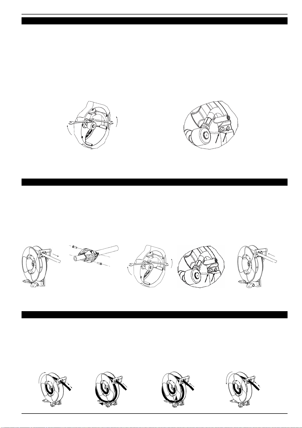
Installation
To reposition the hose guide arm, follow these steps:
Clamp the spool with c-clamp to lock the hose reel (Fig. C).
Remove the hose-stop.
Unscrew the fixing screws (Fig. 5).
Place the hose guide arm in the required position and screw the fixing screws.
Insert the hose reel through the hose outlet and assemble the hose-stop. Affix the hose-stop.
Unlock the spool.
C 5
Issue: 09/2012
Automatic hose reel open - serie 506
www.denios.com 2
Hose installation
Clamp the hose reel firmly to a work bench.
Pretension the hose reel power spring by rotating the spool:
10m spring: 16 turns.
Introduce the hose end to fix to the hose reel through the outlet guide and then through the opening in the drum
of the spool. Pull the hose through the drum towards the swivel.
Fix the hose to the swivel as indicated in Figure 8a and fix the U bolt as shown in Figure 8b.
Fix the hose stop to the free end of the outlet hose.
Pull out the hose slightly to free the spool latch and then gradually release the hose to allow the hose reel to
windup the hose.
If the hose reel does not rewind satisfactorily then adjust the tension of the power spring (see “Spring load
adjustment”).
8a 8b
8a 8b
Hose replacement
WARNING: Before removing the damaged hose, dose the nearest shut off valve to the reel and open
the fluid control gun to release the pressure inside the hose.
Unwind the hose completely and then search for the ratchet blocking position (Fig. 6).
Remove the hose stopper (Fig. 7).
Disconnect the hose as seen (Fig. 8a). Release the hose from the disk by removing the clamp (Fig. 8b).
Pass the new hose through the hose outlet and connect it again to the hose reel. Assemble the clamp and
assemble the hose stopper to the required length.
Pull the hose hard enough to release the latch, and slowly allow the hose to retract (Fig. 9).
6
7
9
Spring load adjustment
1411 12 13
To increase spring tension
Pull the hose out 10 feet (3 meters) and let the hose
get latched (Fig. 11).
Wind the hanging hose in the reel (Fig. 13).
Gently pull the hose, it is automatically winded
(Fig. 14).
Repeat if more spring tension is required.
To decrease spring tension
Pull the hose out 10 feet (3 meters) and let the hose
get latched (Fig. 11).
Unwind one wrap and pull the hose (Fig. 12).
Gently pull the hose, the hose is automatically wind-
ed (Fig. 14).
Repeat if less spring tension is required.
Issue: 09/2012
Automatic hose reel open - serie 506
www.denios.com 3
EC Declaration of Conformity
SAMOA INDUSTRIAL, S.A., Alto de Pumarín, s/n, 33211 - Gijón - Spain, declares declares that the hose reels
506 XXX conform(s) with the EU Directive(s): (2006/42/EEC)
For SAMOA INDUSTRIAL, S.A.
Pedro E. Prallong Alvarez
Production Director
Hose does not rewind Spring is not tensioned enough Increase spring tension
Leaking hose reel Hose has a hole or ís damaged Replace the hose
Leaking swivel Damaged swivel rings Replace the swivel rings
Hose does not extend out as much
as required Spring is over tensioned Decrease spring tension
Hose reel does not latch Damaged ratchet Replace the ratchet
Ratcet not fitted Assemble the ratchet properly
Damaged spring ratchet Change the ratchet spring
Symptom Possible causes Solution
Troubleshooting
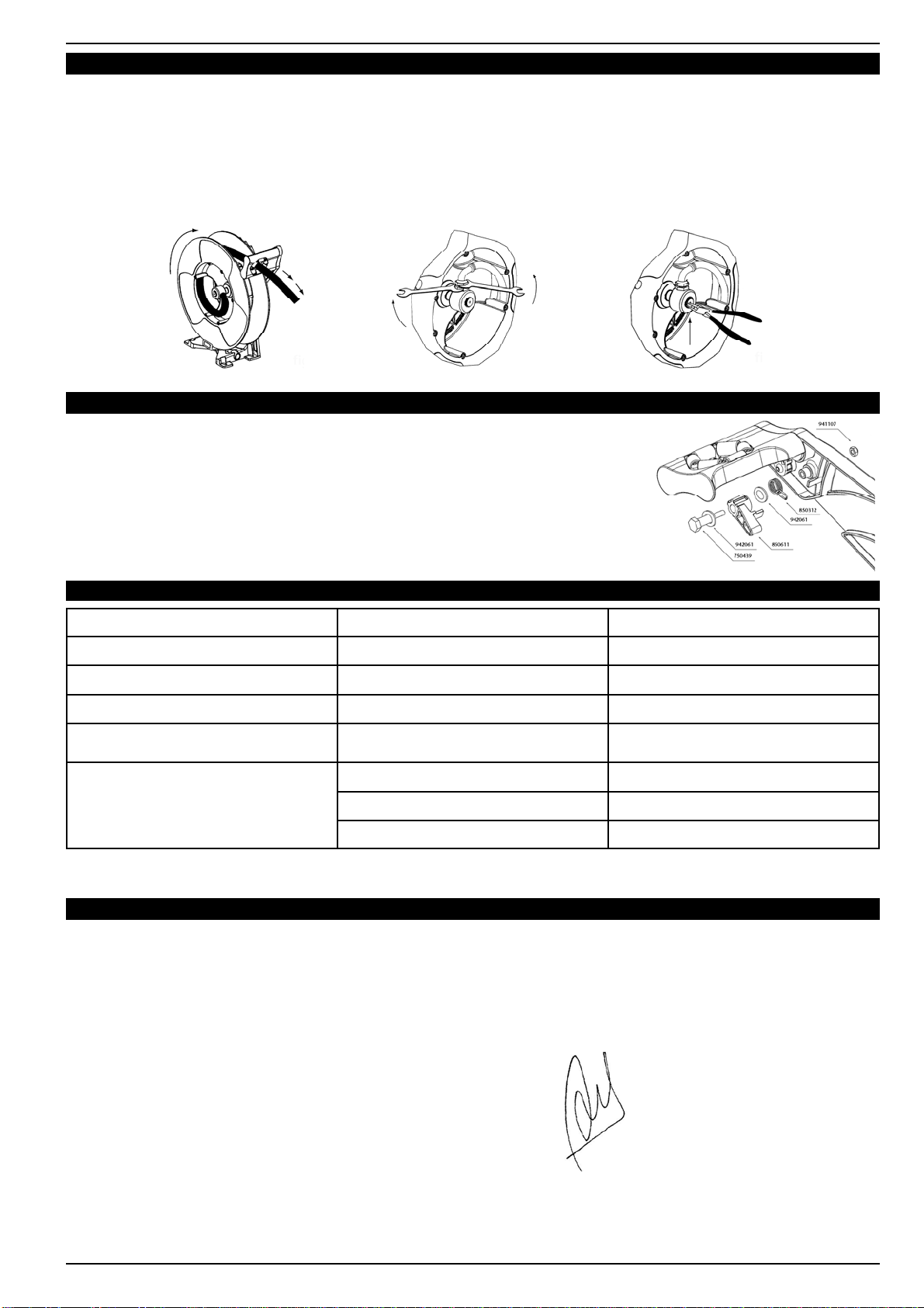
Swivel replacement
WARNING: Before removing the old swivel, dose the nearest shut off valve to the reel and open the
fluid control gun to release the pressure inside the hose.
Pull the hose out and let the hose get latched (Fig. 15).
Unscrew the nuts with two spanners (Fig. 16).
Remove the circlip and pull the swivel. Be careful not to damage the swivel O-Ring (Fig. 17).
Assemble the new swivel and re-assemble the pieces in reverse order.
Ratchet replacement
Remove the nut that fixes the latch (Fig. 18).
Replace the latch and/or the latch spring.
Re-assemble the pieces in reverse order.
15 16 17
18

Issue: 09/2012
Automatic hose reel open - serie 506
www.denios.com 4
Parts list
Kit number Part. N° Description
526010 Oil swivel kit
750425 Body swivel
945593 Fitting R 1/2” - 1/2” - MM
946032 (x2) O-ring NBR
526020 Ratchet kit
850312 Ratchet spring
750439 Ratchet Axle
850611 Ratchet
941107 Nut AISI 316
942061 Washer AISI 316
526021 Hose outlet kit
850616 (x6) Hose roller
750428 (x6) Roller axle
940921 (x6) Screw AISI 316
526001 Hose-stop and U-bolt kit (oil 1/2”)
944816 U-bolt AISI 316
941126 (2) Nut AISI 316
852601 (2) Hose-stop
940610 (2) Screw
941105 (2) Nut
Plate u-bolt AISI 316
Kit number Part. N° Description
526023 Spool and fluid reel shaft kit
850615 Washer
850613 Spool
750424 Low-medium pressure shaft
950510 (x2) Ball bearing
850617 Spacer
850614 Spring cover
940522 (x6) Screw
850442 Spring washer
Part. N° Description
850310 Standard spring (10 m)
This manual suits for next models
3
Table of contents
Other Denios Storage manuals

Denios
Denios PolySafe Euro User manual

Denios
Denios base-line 1 FA User manual

Denios
Denios GF User manual

Denios
Denios HazMat station EPO-2 Guide

Denios
Denios Multistore 19.16 User manual

Denios
Denios SB User manual

Denios
Denios FW-K User manual

Denios
Denios GSN 1.15 User manual

Denios
Denios 158052W User manual

Denios
Denios drum transporter DT EX User manual

Popular Storage manuals by other brands


HP
HP NetServer Common Tray Ultra3 quick start guide

Wangtek
Wangtek 5000 E Basic Series Oem manual

Samsung
Samsung 840 PRO Series Technical specifications

Dell
Dell EMC PowerVault ME4 Series user manual

Seagate
Seagate Momentus Thin ST500LT012 product manual

Infortrend
Infortrend EonStor DS 3000 Series Quick reference guide