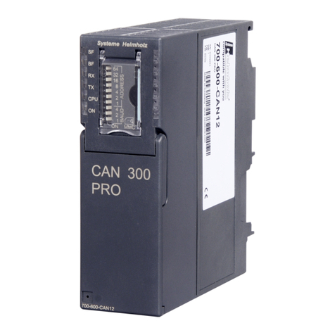
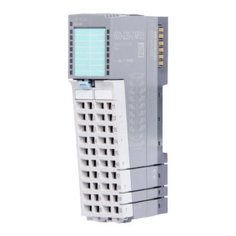
Helmholz DEA 300 Series User manual

Helmholz GmbH & Co. KG | Hannberger Weg 2 | D-91091 Großenseebach
Phone: +49 9135 7380-0 | Fax: +49 9135 7380-110 | E-Mail: inf[email protected] | Internet: www.helmholz.com
DEA 300
Digital Input and Output Modules
700-321-1BL00/-1BH02/-1BH50/-7BH01/-1EL00/-1FH00
700-322-1BL00/-1BH01/-1BF01
700-322-1HF10/-1HF20/-1HF30/-1HF01/-1HH01
700-323-1BL00/-BH01
700-370-0AA01/-0AL01
Manual
Version 12: 05-12-2016
Manual Order Number: 900-321-1GB11/en


All rights are reserved, including those of translation, reprinting,
and reproduction of this manual, or parts thereof. No part of this
manual may be reproduced, processed, copied, or transmitted in
any way whatsoever (photocopy, microfilm, or other method)
without the express written permission of Helmholz GmbH & Co.
KG, not even for use as training material, or using electronic
systems. All rights reserved in the case of a patent grant or
registration of a utility model or design.
Copyright ©2011 by
Helmholz GmbH & Co. KG
Hannberger Weg 2, 91091 Großenseebach, Germany
Note:
We have checked the content of this manual for conformity with
the hardware and software described. Nevertheless, because
deviations cannot be ruled out, we cannot accept any liability for
complete conformity. The information in this manual is regularly
updated. When using purchased products, please heed the latest
version of the manual, which can be viewed in the Internet at
www.helmholz.com, from where it can also be downloaded.
Our customers are important to us. We are always glad to receive
suggestions for improvement and ideas.
STEP, SIMATIC and S7-300 are registered trademarks of SIEMENS AG.
Third parties using for their own purposes any other names in this document which refer to trademarks might infringe
upon the rights of the trademark owners.

Revision history of this document:
Edition
Date
Revision
10 12.12.2011
New module 700-332-1HF30 DO 16 x Rel. DC60V/0.5 A bistable
added. Updated version.
11 08.11.2013
Module 700-332-1HF30 DO 16 x Rel. DC60V/0.5 A bistable
chapter 4.5.5.1 Parameterising and 4.5.5.2 Aktivating the relays
added. Updated version.
12 5.12.16
Hazloc chapter deleted
Change of company name

5 DEA 300
Contents
1Safety Information 7
1.1 General 7
1.2 Restriction of access 8
1.3 Information for the user 8
1.4 Use as intended 8
1.5 Avoiding use not as intended! 8
1.6 Installation and mounting 9
2Mounting 10
2.1 Foreword 10
2.2 Restriction of access 10
2.3 Planning assembly 10
2.4 Minimum clearance 11
2.5 Mounting of the modules on the DIN rail 11
3Wiring 13
3.1 Protection from external electric interference 13
3.2 Current consumption and power loss 13
3.3 Mounting isolated modules 13
3.4 Outdoor cable laying 14
3.5 Protection from inductive overvoltages 14
3.6 Wiring the DEA 300 front connector 16
3.6.1 Wire 40-way connector with screw-type terminal 16
3.6.2 Wire 20-way connector with screw-type terminal 17
3.6.3 Wire 40-way connector with spring contacts 19
3.6.4 Wire 20-way connector with spring contacts 20
3.6.5 Wire 40-way connector with EasyConnect®clamp
connection technique 21
4Digital Modules 22
4.1 Foreword 22
4.2 Digital input modules 22
4.2.1 DEA DI 32 x 24 V DC 22
4.2.2 DEA DI 16 x 24 V DC 24
4.2.3 DEA DI 16 x 24 V DC Source Input 25
4.2.4 DEA DI 16 x 24 V DC with Hardware and Diagnostic
Interrupts 26

DEA 300 6
4.2.5 DEA DI 32 x 120 V AC 36
4.2.6 DEA DI 16 x 120/230 V AC 39
4.3 Digital output modules 42
4.3.1 DEA DO 32 x 24 V DC/0.5 A 42
4.3.2 DEA DO 16 x 24 V DC/0.5 A 44
4.3.3 DEA DO 8 x 24 V DC/2.0 A 46
4.4 Digital input/output modules 48
4.4.1 DEA DI 16/DO 16 x 24 V DC/0.5 A 48
4.4.2 DEA DI 8/DO 8 x 24 V DC/0.5 A 50
4.5 Relay output modules 52
4.5.1 DEA DO 8 x Rel. V AC 230/5 A 52
4.5.2 DEA DO 8 x Rel. 230 V AC/5 A with suppressor 56
4.5.3 DEA DO 16 x Rel. 230 V AC/2 A 60
4.5.4 DEA DO 8 x Rel. 230 V AC/2 A 63
4.5.5 DEA DO 16 x Rel. DC 60 V/0.5 A bistable 66
4.6 Other modules 72
4.6.1 Dummy Module DM 370 72
5Ordering data 76

7 DEA 300
1Safety Information
Please observe the safety information given for your own and other
people's safety. The safety information indicates possible hazards
and provides information about how you can avoid hazards.
The following symbols are used in this manual.
Caution, indicates hazards and sources of error
gives information
hazard, general or specific
danger of electric shock
1.1 General
The DEA 300 Digital Input and Output Modules are only used as
parts of a complete system.
The operator of a machine system is responsible for observing all
safety and accident prevention regulations applicable to the application in
question.
During configuration, safety and accident prevention rules specific
to the application must be observed.
Emergency OFF facilities according to EN 60204 / IEC 204 must
remain active in all modes of the machine system. The system must not
enter an undefined restart.
Faults occurring in the machine system that can cause damage to
property or injury to persons must be prevented by additional external
equipment. Such equipment must also ensure entry into a safe state in the
event of a fault. Such equipment includes, for example, electromechanical
safety buttons, mechanical interlocks, etc. (see EN 954-1, risk estimation).
Never execute or initiate safety-related functions using the
modules.
Make sure in the software that uncontrolled restarts cannot occur.

DEA 300 8
1.2 Restriction of access
The modules are open equipment and must only be installed in
electrical equipment rooms, cabinets, or housings. Access to the
electrical equipment rooms, barriers, or housings must only be
possible using a tool or key and only permitted to personnel having
received instruction or authorization. See also Chapter 2.
1.3 Information for the user
This manual is addressed to anyone wishing to configure, use, or
install the DEA 300 modules.
It is intended to show the user how to operate the DEA 300 and
explain the signaling functions. It provides the installing technician
with all the necessary data.
The DEA 300 module is exclusively for use with an S7-300
programmable controller from Siemens or with a PAS 153 PROFIBUS
Slave Interface from Helmholz.
DEA 300 modules are only used as part of a complete system. For
that reason, the configuring engineer, user, and installing technician
must observe the standards, safety, and accident prevention rules
applicable in the particular application. The operator of the
automation system is responsible for observing these rules.
1.4 Use as intended
The DEA 300 modules must only be used as a communication and
signaling system as described in the manual.
1.5 Avoiding use not as intended!
Safety-related functions must not be controlled using the DEA 300
modules alone. Make sure in the software that uncontrolled restarts
cannot occur. The modules must only be operated in slots connected
to a 5 V data bus.
Only authorized persons
must have access to the
modules!
During configuration it
is impe
rative to observe
the safety and accident
prevention rules
applicable in the
particular application.
Uncontrolled restarts
must be prevented in the
software.

9 DEA 300
1.6 Installation and mounting
Installation and mounting must be effected in compliance with VDE
0100 IEC 364. Because it is an IP20 (OPEN type) module, you must
install it in a (switching) cabinet.
During configuration, safety and accident prevention rules specific to the
application must be observed.
•Use 60/75 °C copper wire only and use 95 °C copper wire only for
model 700-321-1EL00 and 700-321-1FH00.
•Use Class 1 wire only or equivalent.
•Suitable for pollution degree 2 environment only.
•Connected to 5 V bus only.
•See manual for all input and output ratings.
•Maximum surrounding air temperature is 40 °C or 60 °C for
following modules:
700-321-1BH02
700-321-1BL00
700-322-1BH01
700-322-1BL00
700-323-1BH01
700-323-1BL00
700-321-1EL00
700-321-1FH00)
•Date code in year and month of the manufacture on module.
•For Analog Output device 700-332-5HDxx and 700-332-5HBxx:
These modules are intended to be powered by LVLC
programmable controllers S7 series from Siemens.
Before you start
installation work, all
system components must
be disconnected from
their po
wer source.
Note these instructions:

DEA 300 10
2Mounting
2.1 Foreword
This section describes planning of mechanical assembly, preparation
of components for mounting, and final mounting itself.
2.2 Restriction of access
The DEA 300 module must be installed according to VDE 0100
IEC 364. The modules are open equipment and must only be
installed in electrical equipment rooms, cabinets, or housings.
Access to the electrical equipment rooms, barriers, or housings must
only be possible using a tool or key and only permitted to personnel
having received instruction or authorization. See also 1.6.
2.3 Planning assembly
Permissible surrounding air temperature:
•for vertical mounting: from 0 to +40 ºC
•for horizontal mounting: from 0 to +60 ºC
The modules can be
mounted either vertically
or horizontally.
Fig. 2-1:
Vertical and horizontal
mounting
Only authorized persons
must have access to the
modules!

11 DEA 300
2.4 Minimum clearance
Minimum clearances must be observed because
•it ensures cooling of the DEA 300 modules
•it provides space to insert and remove modules
•it provides space to route cables
•it increases the mounting height of the module rack to 185 mm,
although the minimum spacing of 40 mm must still be observed
Fig. 2-2 shows the minimum spacing between the module racks and
between these and any adjacent cabinet walls, equipment, cable
ducts, etc. for DEA 300s mounted in several module racks.
2.5 Mounting of the modules on the DIN rail
Sectional rail 700-390-1xxxx length see chapter 5 Ordering data.
A bus connector is included with each signal module but not with
the CPU. When connecting the bus connector, always start with the
CPU.
Take the bus connector off the last module and insert it into the
CPU. Do not plug a bus connector into the last module of the tier.
Fig. 2-2:
Minimum clearances for
mounting
Non
-observance of the
minimum distances can
destroy the module at
high surrounding air
temperature!

DEA 300 12
Hook on the modules (1), slide them up to the left module (2), and
click them downward (3).
Screw the modules on with a torque of 0.8 to 1.1 Nm.
Fig. 2-3:
Pluggi
ng in bus
connectors
Fig. 2-4:
Using modules
Fig. 2-5:
Screwing modules
tight

13 DEA 300
3Wiring
3.1 Protection from external electric interference
On all systems and plants in which the DEA 300 modules are
installed, it is important to ensure that the system or plant is
connected to a protective ground conductor to remove
electromagnetic interference.
Makes sure that all supply, signal, and bus cables are correctly
installed and that cable routing is correct.
Make sure, for all signal and bus cables, that a conductor or cable
break cannot cause undefined states of the system or plant.
3.2 Current consumption and power loss
DEA 300 modules draw the power they require to operate from the
backplane bus. Where required, they can be powered from an
external source.
•The total current consumption of all signal modules drawn from
the backplane bus must not exceed the current the CPU can
supply to the backplane bus.
•The power loss of all modules used in a cabinet must not exceed
the maximum cabinet power that can be dissipated.
For information about current consumption and power loss of a
module, see the technical data of the module in question.
3.3 Mounting isolated modules
In an assembly containing isolated modules, the reference potentials
of the control circuit (GND internal) and the external load circuit
(GND external) are mutually isolated.
Isolated modules are used for DC load circuits with a separate
reference potential.
Examples of load circuits with a separate reference potential:
•DC load circuits whose sensors have different reference potentials,
for example, if grounded sensors are used at a great distance from
the controller making equipotential bonding between them
impossible.
•DC load circuits, whose plus pole (L +) is grounded.
When dimensioning the
cabinet make sure the
temperature in the
cabinet does not
exceed
60 °C even if the outside
temperature is high.
Isolated modules can be
used irrespective of
whether the reference
potential of the
controller is grounded or
not.

DEA 300 14
3.4 Outdoor cable laying
•The same guidelines apply as for indoor cable laying.
•The cables must be laid on metal cable trays.
•Joints between cable trays must be conductively connected.
•Cable trays must be grounded.
•Adequate equipotential bonding between connected devices must
also be ensured.
•Interior and exterior lightning protection must be ensured and
such grounding measures must be taken as are suitable for the
application in question.
3.5 Protection from inductive overvoltages
The DEA 300 digital output modules feature integrated overvoltage
protection. Overvoltages arise when inductors are switched off, for
example, relay solenoids and contactors.
Inductors only have to be provided with additional overvoltage
protection if:
•the outputs can be switched off by additional built-in contacts,
such as relay contacts.
•the inductors are not controlled by the modules.
Fig. 3-2 shows an example of an output circuit requiring additional
overvoltage protection.
Lighting protection must
always be based on an
individual assessment of
the overall plant.
The inductor supplier
will provide information
about the dimensioning
of overvoltage protection
equipment.
Fig. 3-1:
Potentials in an isolated
module assembly

15 DEA 300
DC-operated solenoids must be connected with diodes or Zener
diodes.
AC-operated solenoids are operated with Varistors or RC elements.
Fig. 3-2:
Relay contact for
EMERG. OFF in the
output circuit
Fig. 3-3:
Relay with snubber
element
Fig. 3-4:
Relay with snubber
element

DEA 300 16
3.6 Wiring the DEA 300 front connector
40-way front connector with screw-type terminal:
Order No 700-392-1AM01
20-way front connector with screw-type terminal:
Order No 700-392-1AJ10
40-way front connector with spring-type terminal:
Order No 700-392-1BM01
20-way front connector with spring-type terminal:
Order No 700-392-1BJ01
40-way front connector with EasyConnect®:
Order No 700-392-1AM10
3.6.1 Wire 40-way connector with screw-type terminal
Technical specifications
Order number
700-392-1AM01
Number of terminals
40
Terminal type
screw-type terminal
Connectable cables
flexible, fixed
Cross-section with/without end ferrules
0,125 – 1,5 mm²
Strip-back length
6 - 8 mm
end ferrules
with or without
Required torque, clamp
0,5 Nm
Required torque, screw
0,7 Nm
Weight
120 g
Fig. 3-5:
Helmholz 20
- and 40-
way front connector

17 DEA 300
•With the cables brought out from the module at the bottom, start
with terminal 40 or 20 and then proceed wiring alternately, in the
sequence of order terminal 39, 19, 38, 18 etc.
•With the cables brought out from the module at the top, start
with terminal 1 or 21 and then proceed wiring alternately in the
sequence of order terminal 2, 22, 3, 23, etc. up to terminals 20
and 40.
•Close unused terminals.
•Lay the supplied strain relief around the cable loom and around
the front connector.
•Screw the strain relief for the cable loom tight, press the lock of
the strain relief to the left inside so that the cable space can be
utilised more efficiently.
3.6.2 Wire 20-way connector with screw-type terminal
Technical specifications
Order number
700-392-1AJ10
Number of terminals
20
Terminal type
screw-type terminal
Connectable cables
flexible, fixed
Cross-section with/without end ferrules
0,25 – 1,5 mm²
Strip-back length
6 mm
end ferrules
with or without
Required torque, clamp
0,5 Nm
Weight
60 g
Fig.
3-6:
Wiring the 40
-
way front
connector

DEA 300 18
•Open the DEA 300 modules (1).
•Snap the front connector into the signal module (2)
•Strip the isolation from the cables.
•When using connector sleeves, crimp the sleeves with the cables.
•Insert the supplied strain relief for the loom of cables into the
front connector (0).
•With the cables brought out from the module at the bottom, start
with terminal 20 and then proceed wiring in the sequence of
order terminal 20, 19, etc. (1) up to terminal 1 (2). Wiring front
connectors
•With the cables brought out from the module at the top, start
with terminal 1 and then proceed wiring in the sequence of order
terminal 1, 2, etc. up to terminal 20.
•In the case of screw-type terminals (3), screw tight also the
connection screws of those screw-type terminals which are not
wired.
•Tighten the strain relief for the loom of cables (4).
•Press the lock of the strain relief to the left inside so that the cable
space can be utilised more efficiently.
Fig.
3-7:
Bringing the front
connector into the wiring
position
Fig. 3-8:
Wiring the 20
-
way front
connector
CAUTION: When the
p
ower supply module
and, in some cases,
additionally, the load
power supplies are
turned on, make
absolutely sure that
nobody is able to come
into contact with alive
lines or cables.

19 DEA 300
3.6.3 Wire 40-way connector with spring contacts
Technical specifications
Order number
700-392-1BM01
Number of terminals
40
Terminal type
spring contacts
Connectable cables
flexible, fixed
Cross-section with/without end ferrules
0,34 – 1,5 mm²
Strip-back length
8 mm
Weight
Approx. 70 g
Easy wiring of front connector with spring contacts: put a
screwdriver (for slotted grub screws 0,6 x 3,5) vertically into the
chamber with the unlock mechanism until mechanical stop, plug
the wire into the spring contact and remove the screwdriver.
Cable routing is similar to the 40 way front connector with screw
contacts.
The unl
ock mechanism
of the front connector
with spring contacts
could be damaged easily
by edgewise movements
of the screwdriver or by
using the wrong
screwdriver.
Use always the right tool
to open the unlock
mechanism!
Fig. 3-9:
Wiring the 40
-
way front
connector

DEA 300 20
3.6.4 Wire 20-way connector with spring contacts
Technical specifications
Order number
700-392-1BJ01
Number of terminals
20
Terminal type
spring contacts
Connectable cables
flexible, fixed
Cross-section with/without end ferrules
0,34 – 1,5 mm²
Strip-back length
8 mm
Weight
Approx. 50 g
Easy wiring of front connector with spring contacts: put a
screwdriver (for slotted grub screws 0,6 x 3,5) vertically into the
chamber with the green unlock mechanism until mechanical stop,
plug the wire into the spring contact and remove the screwdriver.
Cable routing is similar to the 20 way front connector with screw
contacts.
Fig 3-10:
Wiring the 20
-
way front
connector
The unlock mechanism
of the front connector
with spring contacts
could be damaged easily
by edgewise movements
of the screwdriver or by
using the wrong
screwdriver.
Use always the right tool
to open the unlock
mechanism!
This manual suits for next models
18
Table of contents
Other Helmholz Control Unit manuals