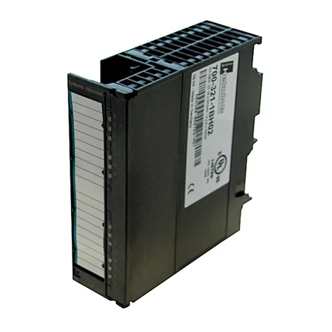
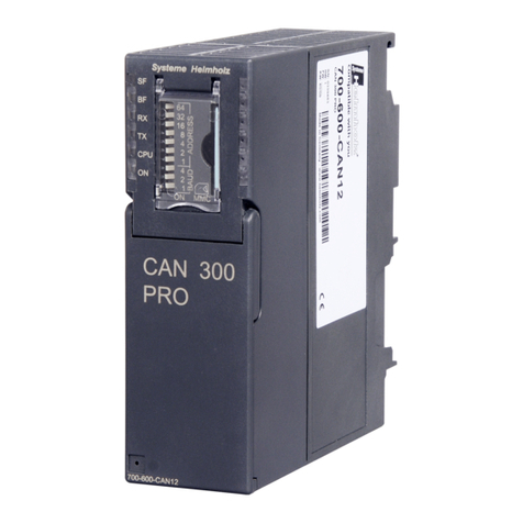
Helmholz CAN 300 PRO User manual

CAN 300 PRO
CAN Communication Module for S7-300
CANopen® Master, CAN Layer 2 or SAE J1939
700-600-CAN12
Manual
Edition 3 / 06.07.2009 / HW30 & FW1.08 and higher
Order number of manual: 900-600-CAN12/en
Systeme Helmholz GmbH zHannberger Weg 2 zD-91091 Großenseebach
Phone: +49 9135 7380-0 zFax: +49 9135 7380-110 zE-mail: info@helmholz.de zInternet: www.helmholz.de


All rights are reserved, including those of translation, reprinting,
and reproduction of this manual, or parts thereof. No part of this
manual may be reproduced, processed, copied, or transmitted in
any way whatsoever (photocopy, microfilm, or other method)
without the express written permission of Systeme Helmholz
GmbH, not even for use as training material, or using electronic
systems. All rights reserved in the case of a patent grant or
registration of a utility model or design.
Copyright ©2009 by
Systeme Helmholz GmbH
Hannberger Weg 2, 91091 Grossenseebach, Germany
Note:
We have checked the content of this manual for conformity with
the hardware and software described. Nevertheless, because
deviations cannot be ruled out, we cannot accept any liability for
complete conformity. The data in this manual are checked
regularly. The latest version of the manual can be downloaded
from the internet at any time at www.helmholz.com.
Our customers are important to us. We are always interested in
ideas for improvement and suggestions.
Step and SIMATIC are registered trademarks of SIEMENS

Revision history of this document:
Edition Date Revision
1 11.03.2009 1st version
2 minor corrections
3 02.07.2009
Behavior of the power LED in the CANopen® Master mode
Correction of the calling parameter of the FCs
Addition of the CANopen® Tools of the CANParam v4.10

Contents
1Safety Information 9
1.1 General 9
1.2 Restriction of access 10
1.3 Information for the user 10
1.4 Use as intended 10
1.5 Avoiding use not as intended! 10
2Installation and Mounting 11
2.1 Vertical and horizontal mounting 11
2.2 Minimum clearance 12
2.3 Mounting of the module on the DIN rail 12
3System Overview 14
3.1 CAN bus 14
3.2 CAN cabling 14
3.3 Application and function description 15
3.4 Connections 16
3.5 LED displays 16
3.6 DIP switch 17
3.7 Project memory card MMC 17
3.8 Items supplied 17
3.9 Accessories 17
4Configuration in the PLC 18
5Process image in the PLC 20
5.1 Byte 0: Module status 20
5.2 Byte 1: Error status (EFLG) of the CAN controller 21
5.3 Byte 2: FIFO status bits 21
5.4 Byte 3/4: CAN controller Tx/Rx error counter 21
5.5 Byte 5: CANopen®master status 22
CAN 300 PRO 5

5.6 Byte 6: Assignment SDO requests
(CANopen®Master) 22
5.7 Byte 7: Nodes in Operational (CANopen®Master) 22
5.8 Byte 8: Active node ID 22
6Configuration of the module 23
6.1 Overview 23
6.2 Installation of the USB interface driver 23
6.3 Creation of a layer 2 project 28
6.3.1 Setting the CAN bus baudrate 29
6.3.2 Setting the transmission mode type 29
6.3.3 Mask filter 30
6.3.4 Bit filter 31
6.3.5 Script events 32
6.3.6 Timer 33
6.3.7 Synchro window 34
6.4 Creation of a CANopen®project 35
6.4.1 Settings of the master 35
6.4.2 Creating a slave 37
6.4.3 Setting TPDOs 38
6.4.4 Setting RPDOs 40
6.4.5 PLC I/O Buffer concept 42
6.4.6 Adding SDOs 44
6.5 Uploading 45
6.6 Downloading 45
6.7 Diagnostics/debugging 45
6.7.1 Layer 2 debug display 45
6.7.2 CANopen Debug display 47
6.8 CANopen®Tools 49
6.8.1 Scan Slaves 49
6.8.2 SDO Transmission 49
6.8.3 Slave Mapping 51
7Programming in the PLC 52
7.1 Overview 52
7.2 Layer 2 handling blocks 53
7.2.1 General 53
7.2.2 FC 65 CANSEND 54
7.2.3 FC 66 CANRCV 55
CAN 300 PRO6

7.2.4 FC 67 CANCTRL 56
7.2.5 Parameter STAT 57
7.3 CANopen®58
7.3.1 General 58
7.3.2 Objects 58
7.3.3 Functions 59
7.3.4 Network management 60
7.4 Start-up behavior of the CANopen®Master 62
7.5 Operating conditions for CANopen®Slave devices 63
7.6 Tips on start-up / troubleshooting 64
7.7 CANopen data handling modules 65
7.7.1 FB 20 CANopen®IO Read 66
7.7.2 FB 21 CANopen®IO Write 67
7.7.3 FB 22 CANopen®Service 68
7.7.4 FB 23 CANopen®network management 70
7.7.5 FB 24 CANopen®SDO 71
7.7.6 FB 27 CANopen®SDO Segmented 73
7.7.7 FB 25 CANopen®L2 Receive 75
7.7.8 FB 26 CANopen®PDO resend 76
7.7.9 FB 28 CANopen®SYNC trigger 77
7.8 SDO abort codes 78
7.9 SAE J1939 communication 79
7.9.1 General 79
7.9.2 FC 70 CANSEND_SAE_J1939 80
7.9.3 FC 71 CANRCV_SAE_J1939 81
8Return parameter RETVAL 82
9Upgrading from CAN 300 to CAN 300 PRO83
9.1 Differences between CAN 300 and CAN 300 PRO 83
9.2 Layer 2 83
9.3 SAE J1939 83
9.4 CANopen®84
CAN 300 PRO 7

1Safety Information
Please observe the safety information given for your own and
other people's safety. The safety information indicates possible
hazards and provides information about how you can avoid
hazardous situations.
The following symbols are used in this manual.
!
Caution, indicates hazards and sources of error
i
Gives information
Hazard, general or specific
Danger of electric shock
1.1 General
The CAN 300 PRO module is only used as part of a complete
system.
!
The operator of a machine system is responsible for observing
all safety and accident prevention regulations applicable to the
application in question.
During configuration, safety and accident prevention rules
specific to the application must be observed.
Emergency OFF facilities according to EN 60204 / IEC 204
must remain active in all modes of the machine system. The system
must not enter an undefined restart.
Faults occurring in the machine system that can cause
damage to property or injury to persons must be prevented by additional
external equipment. Such equipment must also ensure entry into a safe
state in the event of a fault. Such equipment includes electromechanical
safety buttons, mechanical interlocks, etc. (see EN 954-1, risk
assessment).
Never execute or initiate safety-related functions using the
operator terminal.
CAN 300 PRO 9

1.2 Restriction of access
The modules are open equipment and must only be installed in
electrical equipment rooms, cabinets, or housings. Access to the
electrical equipment rooms, barriers, or housings must only be
possible using a tool or key and only permitted to personnel
having received instruction or authorization. See also Section 2.
Only authorized persons
must have access to the
modules!
1.3 Information for the user
This manual is addressed to anyone wishing to configure or
install the CAN 300 PRO module.
It is intended for use as a programming manual and reference
work by the configuring engineer. It provides the installing
technician with all the necessary data.
The CAN 300 PRO module is exclusively for use in a S7-300
programmable controller from Siemens. For that reason, the
configuring engineer, user, and installing technician must observe
the standards, safety and accident prevention rules applicable in
the particular application. The operator of the automation system
is responsible for observing these rules.
1.4 Use as intended
The CAN 300 module must only be used as a communication
system as described in the manual.
1.5 Avoiding use not as intended!
Safety-related functions must not be controlled using the CAN
300 PRO module alone.
CAN 300 PRO10

2Installation and Mounting
The CAN 300 PRO module must be installed according to VDE
0100 IEC 364. Because it is an “OPEN type” module, you must
install it in a (switching) cabinet. Ambient temperature: 0 ºC –
60 ºC.
Before you start installation work, all system components
must be disconnected from their power source.
Danger of electric shock!
During installation, application-specific safety and accident
prevention rules must be observed.
2.1 Vertical and horizontal mounting
The modules can be mounted either vertically or horizontally.
Permissible ambient temperature:
for vertical mounting: from 0 to 40 ºC
for horizontal mounting: from 0 to 60 ºC
CAN 300 PRO 11

2.2 Minimum clearance
Minimum clearances must be observed because
it ensures cooling of the CAN 300 PRO modules
it provides space to insert and remove modules
it provides space to route cables
it increases the mounting height of the module rack to 185 mm,
although the minimum spacing of 40 mm must still be
observed
The following diagram shows the minimum spacing between the
module racks and between these and any adjacent cabinet walls,
equipment, cable ducts, etc. for S7-300s mounted in several
module racks.
Non-observance of the
minimum distances can
destroy the module at
high ambient
temperatures!
2.3 Mounting of the module on the DIN rail
A bus connector is included with each signal module but not with
the CPU. When connecting the bus connector, always start with
the CPU.
Take the bus connector off the last module and insert it into the
CPU. Do not plug a bus connector into the last module of the
tier.
CAN 300 PRO12

Hook on the modules (1), slide them up to the left module, and
click them downward (3).
Screw the modules on with a torque of 0.8 to 1.1 Nm.
CAN 300 PRO 13

3System Overview
3.1 CAN bus
The CAN bus (Control Area Network) is an international and
open field bus standard for applications in building, production,
and process automation.
The comprehensive error detection measures make the CAN bus
currently the most reliable bus system with a residual error
probability of less than 4.7 x 10⁻¹¹.
3.2 CAN cabling
A CAN bus cable requires at least 3 conductors: CAN High, CAN
Low, and CAN Ground. Only a bus topology is permitted. At both
ends of the CAN bus cable, a terminating resistor of 120 ohms
must be connected between CAN High and CAN Low. The CAN
300 PRO module does not have an integrated terminating resistor.
i
No terminating resistor
is integrated into the
CAN 300 PRO module.
The maximum cable lengths primarily depend on the baudrate
used.
Bit rate Bus length Bit time
1 Mbps 30 m 1 µsec.
800 Kbps 50 m 1.25 µsec.
500 Kbps 100 m 2 µsec.
250 Kbps 250 m 4 µsec.
125 Kbps 500 m 8 µsec.
20 Kbps 2,500 m 50 µsec.
10 Kbps 5,000 m 100 µsec.
The cable lengths stated are for guidance only. The maximum
cable length also depends on the number of connected stations
and the type of cable.
More precise information is available in the document
“CANopen®Recommendation DR 303-1” that is provided on the
CD of the software package.
Check for correct cabling in the debug dialog box of the
CANParam (see also Section 6.7).
CAN 300 PRO14

3.3 Application and function description
The CAN 300 PRO module from System Helmholz GmbH allows
you to connect any CAN stations to the programmable controller.
The module is plugged into the backplane bus of the
programmable controller. It can be used both in the central
controller and in the expansion rack (e.g. with the IM360, 361,
365). Use of the CAN 300 PRO is also possible in an ET200M
(with IM153), but this drastically reduces the performance.
The CAN 300 PRO module must be parameterized as a
communication module in the hardware configurator and takes
up 16 bytes in the analog process image. Data is exchanged with
the PLC via the backplane bus.
Data handling blocks that enable simple handling of CAN
communication are contained in the separately available software
package. Data handling blocks are available both for simple layer
2 communication, SAE J1939, and for CANopen®master
communication. Data handling software for use of the CAN 300
PRO module as a CANopen®slave is available on request.
The scope of supply of the software package also includes the
Windows parameterization tool “CANParam V4” for setting the
CAN bus communication parameters and for creating CANopen®
Master projects.
The CAN 300 PRO module supports both CAN 2.0A (11 bits) and
CAN 2.0B (29 bits) frames as a high-speed node according to ISO
11898-2 with a freely selectable baudrate of 10Kbps to 1Mbps.
The CAN 300 PRO module contains the power management
functions "Power On," "Stop>>Run," and "Run>>Stop." Behind
each of the three functions, it is possible to use a simple macro
language to configure a CAN bus response with up to 100 frames
per script that is executed automatically by the module when the
event occurs.
In a multi-level acceptance mask it is possible to prefilter the IDs
relevant to the programmable controller. Only those CAN frames
are accepted that are required, which off-loads the cycle of the
programmable controller.
16 freely settable timers are available in the CAN 300 PRO
module. Each timer can trigger a freely programmable CAN
frame. That way, it is easy to implement the synchronous
protocols in common use in drive and servo systems using the
CAN 300 PRO module.
It is also possible to have the data sent via the CAN bus only in a
time window. The data to be transmitted are transferred non-
cyclically by the programmable controller and transmitted from
the CAN 300 PRO module after the parameterized time has
elapsed.
CAN 300 PRO 15

3.4 Connections
The CAN 300 PRO module has behind the hinged front cover a 9-
way SubD connector for the CAN bus and an USB connector for
configuration and diagnostics.
Pin assignment:
Pin SUBD connector CAN
1 -
2 CAN Low
3 CAN GND
4 -
5 -
6 -
7 CAN High
8 -
9 -
i
A
24V power supply is
not applied to the CAN
bus connector.
3.5 LED displays
The LEDs on the front of the module inform you about its
operating state.
LED “SF” (orange):
System error: shows a project that has an
error or a memory card with an error or
that is too small.
LED “BF” (red):
This LED indicates a CAN error. A CAN
error has occurred if the error counter is
not zero, the CAN status is not “OK,” or a
CAN FIFO overflow has occurred. You
can obtain further information in debug mode of the CANParam
software (see also Section 6.7).
LED “RX” (green):
CAN bus reception active: Indicates correct reception of a CAN
frame.
LED “TX” (orange):
CAN bus transmission active: Indicates correct transmission of a
CAN frame.
LED “CPU” (orange):
Data transmission to the PLC active: Indicates transmission of a
frame or command on the backplane bus (between the S7-CPU
and the module).
LED “ON” (green):
Indicates that the module is correctly supplied with power and
that the operating system is running.
CAN 300 PRO16

A blinking LED shows the master state is not “operational” in the
CANopen®master mode.
3.6 DIP switch
The 10-fold DIP switch on the front of the
housing is for setting the CAN baudrate
and for defining the node address (Bit-
filter) to use the module as a CANopen
slave.
26+ 64
25+ 32
24+ 16
23+ 8
22+ 4
21+ 2
Address
20+ 1
22+ 4
21+ 2
Baud
20+ 1
Baudrates:
0 1 2 3 4 5 6 7
10K 50K 100K 125K 250K 500K 800K 1M
3.7 Project memory card MMC
The CAN 300 PRO module stores the project in an internal
memory (256 KByte). As an option, the project can be stored on
an MMC. With the MMC, the valid project can be transferred
onto the new module when the module is replaced.
If an MMC is in the slot of the module, this is also copied to the
MMC when the project is transferred to the module.
I
f a faulty or too small
M
MC is plugged into the
CAN 300 PRO module,
the SF-LED lights up.
The MMC must have a memory capacity of at least 256Kbyte.
Micro Memory Card, 256Kbyte 700-953-8LH11
3.8 Items supplied
CAN 300 PRO module, bus connector, USB cable
3.9 Accessories
CAN CD with parameterization software “CANParam,”
“Layer 2”, “CANopen®” and “SAE J1939” data handling blocks
800-600-1AA11
Manual, German/English 900-600-CAN01
CAN bus plug connector 700-690-0BA12
CAN bus plug connector with cable connector 700-690-0BB12
CAN bus plug connector with axial cable outlet 700-690-0CA11
CAN 300 PRO 17

4Configuration in the PLC
The CAN 300 PRO module is configured as the CP 340
communication module in the programming software of the PLC.
When the CAN 300
P
RO module is used in
an ET200M system,
noticeably poorer
p
erformance must be
expected.
The module can be used wherever a CP module is allowed, i.e.
also in the expansion unit after an interface module.
CAN 300 PRO18

In parameterization of the module, only the range of I/O
addresses is relevant. All other settings have no effect on the
module.
The I/O addresses
should not be in the
cyclic process image!
Only the input image is used in the data handling blocks; the
output image has no relevance to the function.
Accesses to the input image can only be performed with the I/O
direct access commands: L PEB, L PEW, L PED.
For CPU 318 the IO-addresses must never address in cyclic
memory area.
CAN 300 PRO 19

5Process image in the PLC
The CAN 300 PRO module occupies 16 bytes in the input and
output process image. The content of the output process image is
not used.
The content of the input process image can be used for infor-
mation purposes by the user in the application.
Byte Function
0 Module status generally, CAN group error display
1 CAN controller status (register of the CAN controller)
2 FIFO status bits (send & receive)
3 CAN controller: TX error counter
4 CAN controller: RX error counter
5 CANopen®: Master status
6 CANopen®: Assignment of the SDO request mailboxes
7 CANopen®: Number of nodes in operational
8 Node ID on use of the bit filter or of the master
9 reserved
10 reserved
11…15 used internally
Accesses to the input image can only be performed with the I/O
direct access commands: L PIB, L PIW, L PID.
Bytes 5, 6, and 7 are only assigned data that can be evaluated in
the CANopen®Master mode.
5.1 Byte 0: Module status
Bit 7 Bit 6 Bit 5 Bit 4 Bit 3 Bit 2 Bit 1 Bit 0
CAN controller
group error Module is
CAN 300 PRO
Module
parameterized
and running
Bit 0: The CAN 300 PRO module has processed the configuration
and is ready for operation.
Bit 1: The Bit is always 1 to indicate a CAN 300 PRO module is
plugged.
Bit 7: Group error bit for errors on the CAN controller, more
precise information about the cause of error can be found in
byte 1.
CAN 300 PRO20
Other manuals for CAN 300 PRO
1
Table of contents
Other Helmholz Control Unit manuals
Popular Control Unit manuals by other brands

Stid
Stid ARC1-XY installation instructions

Jafar
Jafar 3500 operating manual

Burkert
Burkert 6712 operating instructions

LEGRAND
LEGRAND Wattstopper ELCU-100 installation instructions

AWID
AWID SENTINEL-SENSE MPR-1510 Installation & operation manual

Siemens
Siemens ECOFAST 3RK1911-4AB Series operating instructions