Helmholz WALL IE 700-860-WAL01 User manual

Helmholz GmbH & Co. KG | Hannberger Weg 2 | 91091 Großenseebach | Germany
Phone +49 9135 7380-0 | Fax +49 9135 7380-110 | info@helmholz.de | www.helmholz.com
WALL IE, Industrial Ethernet Bridge and Firewall
Manual
Version 1 | 5/15/2017 | as of firmware V 1.04
Manual order number: 900-860-WAL01

Notes
All rights reserved, including those related to the translation, reprinting, and reproduction of this
manual or of parts thereof.
No part of this manual may be reproduced, processed, duplicated, or distributed in any form
(photocopy, microfilm, or any other methods), even for training purposes or with the use of
electronic systems, without written approval from Helmholz GmbH & Co. KG.
To download the latest version of this manual, please visit our website at www.helmholz.de.
We welcome all ideas and suggestions.
Our products contain open source software, among others. This software is subject to the respectively
relevant license conditions. We can send you the corresponding license conditions, including a copy
of the complete license text together with the product. They are also provided in our download area of
the respective products under www.helmholz.de.
We also offer to send you or any third party the complete corresponding source text of the respective
open source software for an at-cost fee of 10.00 Euro as a DVD upon request. This offer is valid for a
period of three years, starting from the date of product delivery.
Copyright © 2017 by
Helmholz GmbH & Co. KG
Hannberger Weg 2 | 91091 Großenseebach
STEP, TIA, and SIMATIC are registered trademarks of Siemens AG.
Windows is a registered trademark of Microsoft Corporation.
Revision Record:
Version
Date
Change
1
12.5.2017
First version / Firmware V1.04

WALL IE, Industrial Ethernet Bridge and Firewall | Version 1 | 15.05.2017 3
Contents
1General............................................................................................................. 5
1.1 Target audience for this manual............................................................................................... 5
1.2 Safety instructions ................................................................................................................... 5
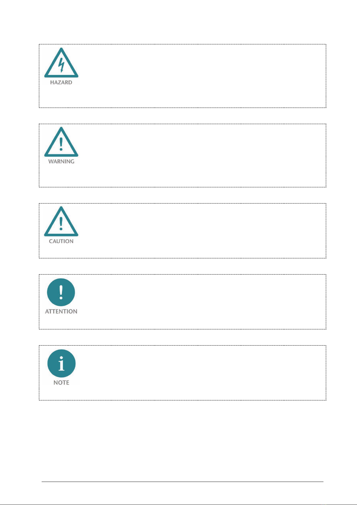
1.3 Note symbols and signal words ............................................................................................... 6
1.4 Intended use ........................................................................................................................... 7
1.5 Improper use........................................................................................................................... 7
1.6 Installation............................................................................................................................... 8
1.6.1 Access restriction ................................................................................................................. 8
1.6.2 Electrical installation ............................................................................................................ 8
1.6.3 Protection against electrostatic discharges ........................................................................... 8
1.6.4 Overcurrent protection ........................................................................................................ 8
1.6.5 EMC protection ................................................................................................................... 8
1.6.6 Operation ............................................................................................................................ 8
1.6.7 Liability ................................................................................................................................ 9
1.6.8 Disclaimer of liability............................................................................................................ 9
1.6.9 Warranty.............................................................................................................................. 9
2Overview ........................................................................................................10
2.1 Setup..................................................................................................................................... 10
2.2 Connection of the power supply ........................................................................................... 11
2.3 LEDs status information ......................................................................................................... 11
3Initial access to the web interface...................................................................12
3.1 Initial Login............................................................................................................................ 13
3.2 Main view.............................................................................................................................. 14
3.2.1 Menu overview.................................................................................................................. 14
3.2.2 Responsive design ............................................................................................................. 15
3.3 Adjustment of the IP addresses (Network interface) ............................................................... 16
4The bridge mode ............................................................................................ 17
4.1 Activate bridge mode ............................................................................................................ 17
5Packet filter functionality ...............................................................................19
5.1 Creation of rules in the packet filter ....................................................................................... 19
6NAT operating mode ...................................................................................... 21
6.1 Basic NAT .............................................................................................................................. 22
6.2 NAPT ..................................................................................................................................... 23

WALL IE, Industrial Ethernet Bridge and Firewall | Version 1 | 15.05.2017 4
6.3 Port forwarding ..................................................................................................................... 24
7MAC address filtering .....................................................................................26
8Static routes....................................................................................................27
9Use with Simatic Step 7 / TIA portal ............................................................... 28
9.1 Solution in Step 7 .................................................................................................................. 29
9.2 Use in the TIA portal .............................................................................................................. 30
9.3 Setting up a route on the PC.................................................................................................. 32
10 Other functions............................................................................................33
10.1 Syslog server ......................................................................................................................... 33
10.1.1 Syslog local.................................................................................................................... 33
10.1.2 Syslog remote................................................................................................................ 33
10.2 Change password (Password)................................................................................................ 34
10.3 File certificate (HTTPS) ........................................................................................................... 34
10.4 Allow web interface access to WAN (Web Interface Access).................................................... 34
10.5 Firmware update ................................................................................................................... 35
10.6 Time settings (Time) .............................................................................................................. 36
10.7 Export/import of configuration .............................................................................................. 37
11 Resetting to factory settings ........................................................................ 38
11.1 Resetting to factory settings via the website........................................................................... 38
11.2 Resetting to factory settings with button ............................................................................... 38
12 Technical data..............................................................................................39
12.1 Dimensioned drawing ........................................................................................................... 39

WALL IE, Industrial Ethernet Bridge and Firewall | Version 1 | 15.05.2017 5
1General
This operating manual applies only to devices, assemblies, software, and services of Helmholz GmbH
& Co. KG.
1.1 Target audience for this manual
This description is only intended for trained personnel qualified in control and automation
engineering who are familiar with the applicable national standards. For installation, commissioning,
and operation of the components, compliance with the instructions and explanations in this
operating manual is essential.
Configuration, execution, and operating errors can interfere with the proper operation of the PN/CAN
gateways and result in personal injury, as well as material or environmental damage. Only suitably
qualified personnel may operate the devices!
Qualified personnel must ensure that the application and use of the products described meet all the
safety requirements, including all relevant laws, regulations, provisions, and standards.
1.2 Safety instructions
The safety instructions must be observed in order to prevent harm to living creatures, material goods,
and the environment. The safety notes indicate possible hazards and provide information about how
hazardous situations can be prevented.

WALL IE, Industrial Ethernet Bridge and Firewall | Version 1 | 15.05.2017 6
1.3 Note symbols and signal words
If the hazard warning is ignored, there is an imminent danger to life and health of people from electrical
voltage.
If the hazard warning is ignored, there is a probable danger to life and health of people from electrical
voltage.
If the hazard warning is ignored, people can be injured or harmed.
Draws attention to sources of error that can damage equipment or the environment.
Gives an indication for better understanding or preventing errors.

WALL IE, Industrial Ethernet Bridge and Firewall | Version 1 | 15.05.2017 7
1.4 Intended use
The WALL IE Industrial Ethernet Bridge and Firewall ("the device" in the following) connects two
Ethernet networks.
All components are supplied with a factory hardware and software configuration. The user must carry
out the hardware and software configuration for the conditions of use. Modifications to hardware or
software configurations which extend beyond the documented options are not permitted and nullify
the liability of Helmholz GmbH & Co. KG.
The device may not be used as the only means for preventing hazardous situations on machinery and
systems.
Successful and safe operation of the device requires proper transport, storage, setup, assembly,
installation, commissioning, operation, and maintenance.
The ambient conditions provided in the technical specifications must be adhered to.
The device has a protection rating of IP 20 and must be installed in an electrical operating room or a
control box/cabinet in order to protect it against environmental influences. To prevent unauthorized
access, the doors of control boxes/cabinets must be closed and possibly locked during operation.
1.5 Improper use
The consequences of improper use may include personal injury to the user or third parties, as well as
property damage to the control system, the product, or the environment. Use the device only as
intended!

WALL IE, Industrial Ethernet Bridge and Firewall | Version 1 | 15.05.2017 8
1.6 Installation
1.6.1 Access restriction
The modules are open operating equipment and must only be installed in electrical equipment
rooms, cabinets, or housings.
Access to the electrical equipment rooms, cabinets, or housings must only be possible using a tool or
key, and access should only be granted to trained or authorized personnel.
1.6.2 Electrical installation
Observe the regional safety regulations.
1.6.3 Protection against electrostatic discharges
To prevent damage through electrostatic discharges, the following safety measures are to be followed
during assembly and service work:
•Never place components and modules directly on plastic items (such as polystyrene, PE film) or in
their vicinity.
•Before starting work, touch the grounded housing to discharge static electricity.
•Only work with discharged tools.
•Do not touch components and assemblies on contacts.
1.6.4 Overcurrent protection
Overcurrent protection isn't necessary as the device transports no load current. The power supply of
the device electronics is to be secured externally with a fuse of maximum 1 A (slow-blowing).
1.6.5 EMC protection
To ensure electromagnetic compatibility (EMC) in your control cabinets in electrically harsh
environments, the known rules of EMC-compliant configuration are to be observed in the design and
construction.
1.6.6 Operation
Operate the device only in flawless condition. The permissible operating conditions and performance
limits must be adhered to.
Retrofits, changes, or modifications to the device are strictly forbidden.
The device is a piece of operating equipment intended for use in industrial plants. During operation,
all covers on the unit and the installation must be closed in order to ensure protection against
contact.

WALL IE, Industrial Ethernet Bridge and Firewall | Version 1 | 15.05.2017 9
1.6.7 Liability
The contents of this manual are subject to technical changes resulting from the continuous
development of products of Helmholz GmbH & Co. K. In the event that this manual contains
technical or clerical errors, we reserve the right to make changes at any time without notice.
No claims for modification of delivered products can be asserted based on the information,
illustrations, and descriptions in this documentation. Beyond the instructions contained in the
operating manual, the applicable national and international standards and regulations must also be
observed in any case.
1.6.8 Disclaimer of liability
Helmholz GmbH & Co. KG is not liable for damages if these were caused by use or application of
products that was improper or not as intended.
Helmholz GmbH & Co. KG assumes no liability for any printing errors or other inaccuracies that may
appear in the operating manual, unless there are serious errors of which Helmholz GmbH & Co. KG
was already demonstrably aware.
Beyond the instructions contained in the operating manual, the applicable national and
international standards and regulations must also be observed in any case.
Helmholz GmbH & Co. KG is not liable for damage caused by software that is running on the user’s
equipment which compromises, damages, or infects additional equipment or processes through the
remote maintenance connection, and which triggers or permits unwanted data transfer.
1.6.9 Warranty
Report any defects to the manufacturer immediately after discovery of the defect.
The warranty is not valid in case of:
•Failure to observe these operating instructions
•Use of the device that is not as intended
•Improper work on and with the device
•Operating errors
•Unauthorized modifications to the device
The agreements met upon contract conclusion under “General Terms and Conditions of Helmholz
GmbH & Co. KG” apply.

WALL IE, Industrial Ethernet Bridge and Firewall | Version 1 | 15.05.2017 10
2Overview
WALL IE, the new Industrial Ethernet Bridge and Firewall, simply integrates your machinery network
into the higher-level production network. A packet filter protects the networks from unauthorized
access. If identical IP address ranges are to be realized, WALL IE functions as a bridge.
The NAT operating mode serves the forwarding of the data traffic between various IPv4 networks. It
enables the address translation via NAT and uses packet filters for the limitation of access to the
automation network located behind.
In the bridge operating mode, WALL IE acts as a layer 2 switch. In contrast with normal switches,
however, packet filtering is also possible in this operating mode. This means that the restriction of
access to individual areas of your network can be achieved without having to use different networks
for this purpose.
WALL IE features:
•Bridge functionality for identical IP address ranges
•NAT (Basic NAT, NAPT and port forwarding)
•Access restriction through packet filters: IPv4 addresses, protocol (TCP/UDP), ports
•MAC addresses, black and whitelisting
•Quick and easy configuration thanks to responsive web interface
•Static routes to other networks
•Reporting of events to a Syslog server
•Export/import of configuration
•Industry-compatible design for installation on DIN rails
2.1 Setup
The WALL IE has a 100 Mbps WAN port (P1) and three 100 Mbps LAN ports (P2-P4) that have been
switched.
A reset to factory settings can be initiated with the function button (FCN) (see ch. 11). The reset
button (RST) initiates a restart of the WALL IE.

WALL IE, Industrial Ethernet Bridge and Firewall | Version 1 | 15.05.2017 11
2.2 Connection of the power supply
The WALL IE is connected with 24 V DC voltage via the 5-pin power supply socket. There is also a
connection for the functional ground (FG). The connection of a functional ground is recommended.
The inputs IN1 and IN2 do not yet have a function in the current firmware version, but will be
available in a later firmware version for the external switching of firewall rules.
2.3 LEDs status information
PWR
Off
No power supply or device defective.
On
Device is correctly supplied with voltage.
RDY
On
Device is ready to operate.
ACT Flashing light or
ON
Data transfer permitted between WAN and LAN.
USR
On
Factory settings reset active.
RJ45 LEDs
Green (Link)
Connected
Orange (Act)
Data transfer at the port

WALL IE, Industrial Ethernet Bridge and Firewall | Version 1 | 15.05.2017 12
3Initial access to the web interface
The WALL IE is set on the LAN-side at the factory with the IP address 192.168.0.100 and the subnet
mask 255.255.255.0. Access to the web interface is only possible via the LAN connections P2—P4.
The IP address of your network adapter
must first be set in accordance with the
IP subnet of the WALL IE:
Start control panel
Network and sharing settings
Adapter settings
LAN connection properties
Internet Protocol Version 4
Now connect a patch cable with the LAN connection of your PC and one of the LAN ports P2- P4 of
the WALL IE.
The web interface can be reached in the delivery condition by calling up "https://192.168.0.100" in
the browser page.

WALL IE, Industrial Ethernet Bridge and Firewall | Version 1 | 15.05.2017 13
For security reasons, the web interface can only be reached through a secured HTTPS connection. An
exception rule needs to be confirmed once in order to reach the website. A certificate for the connection
authentication can be stored in the "Device/HTTPS" menu.
3.1 Initial Login
You will be prompted to set a password at the initial Login.
The password must have at least 8 characters and may have a maximum of 128 characters. It may
contain special characters and numbers. With the "Continue" button, the password is stored in the
device and you will be forwarded to the "Overview" page of the WALL IE.
The main user is always "admin".
Additional user management hasn't
been implemented yet.
Please note the password well! For security reasons there is no possibility to reset the password without
resetting the device to the factory settings.

WALL IE, Industrial Ethernet Bridge and Firewall | Version 1 | 15.05.2017 14
3.2 Main view
The "Overview" main view contains an overview of the most important settings and information of
the WALL IE. The topmost line contains the menu with the functions for configuration.
3.2.1 Menu overview

WALL IE, Industrial Ethernet Bridge and Firewall | Version 1 | 15.05.2017 15
3.2.2 Responsive design
The web interface is also suitable for use on tablets and smartphones ("Responsive design").
Please note that web access to the WALL IE is equipped with inactivity monitoring for security reasons.
When the website isn't used for several minutes, an automatic "log out" takes place.

WALL IE, Industrial Ethernet Bridge and Firewall | Version 1 | 15.05.2017 16
3.3 Adjustment of the IP addresses (Network interface)
Click on the "Network" menu and select the sub-menu "Interface".
The desired IP addresses for LAN and WAN and the related subnet masks (LAN/WAN net mask) can be
defined here.
The default gateway is necessary when devices from the LAN wish to establish a connection with the
Internet or when devices from the LAN should communicate with other networks via WAN. If this is
not permitted or is not desired, "0.0.0.0" is to be entered.
A DNS server can also be indicated where necessary. It is necessary to indicate a DNS server for the
SNTP service (see ch. 10.6).
The entry is saved with the "Save" button and the IP addresses are activated immediately. The current
entry is rejected without acceptance with "Decline."
When you change the LAN IP address, you may need to reopen the website of the WALL IE in the
browser under the new IP address and log in again.
The WALL IE always only has one active configuration. Changes to the configuration are always activated
immediately. A restart of the WALL IE is not required.

WALL IE, Industrial Ethernet Bridge and Firewall | Version 1 | 15.05.2017 17
4The bridge mode
In the bridge operating mode, WALL IE behaves like a layer 2 switch between the automation cell
(LAN) and the production network (WAN). The packet filter can be used to limit access between the
two areas. This enables the separation of a part of the production network without using different
network addresses.
4.1 Activate bridge mode
Switch the WALL IE to the bridge mode via "Device Operating Mode Bridge."
In the bridge mode, the IP address of the WAN
interface is identical to the IP address of the
LAN interface. It is thus transparent.
When setting the IP addresses of the WALL IE under
"Network Interface," only one IP address can be set
in the bridge mode as a result:

WALL IE, Industrial Ethernet Bridge and Firewall | Version 1 | 15.05.2017 18
In the bridge mode, all ports are blocked for "WAN-to-LAN" data transfer as a default!
In order to enable access, packet filter rules must be created or the default action for the packet filters be
set to "Accept".
The "LAN to WAN" data transfer is initially always allowed, but can also be limited by packet filters or the
default action.

WALL IE, Industrial Ethernet Bridge and Firewall | Version 1 | 15.05.2017 19
5Packet filter functionality
The packet filters define the of access between the production network (WAN) and the automation
cell (LAN) in both directions. For example, it can be configured that only certain participants from the
production network may exchange data with defined participants
from the automation cell.
The following filter criteria on layers 3 and 4 are available:
•IPv4 addresses
•Protocol (TCP/UDP)
•Ports
The packet filters are available in both the "WAN to LAN" direction and in the direction "LAN to
WAN".
5.1 Creation of rules in the packet filter
In the "Packet Filter" menu, select "WAN to LAN" or "LAN to WAN", depending upon which
communication direction you wish to restrict.
With the "Default Action" option you can set how the standard action of the packet filter should
work.
In the "Accept" setting, all frames are generally permitted and only special packets are filtered.
In the "Reject" or "Drop" settings, all frames are generally prohibited and only the frames indicated in
the filter rules are accepted. "Reject" hereby rejects frames with an error message. "Drop" rejects frames
without error messages.
Whitelisting can be realized with "Accept," blacklisting with "Reject" or "Drop."
With the option "ICMP Traffic", you can allow the passage of ICMP packets - e.g. a "Ping".

WALL IE, Industrial Ethernet Bridge and Firewall | Version 1 | 15.05.2017 20
A new rule is entered with the symbol.
In the example above, a PC in the WAN network with the IP address 10.10.1.10 (e.g. visualization) is
now allowed access to the CPU 10.10.1.30 in the LAN network via port 102 with the TCP protocol.
Source IP
IP address of the device in the external network (WAN) from which the query originates.
Destination IP
IP address of the device in the internal network (LAN) on which access is allowed by this rule.
Protocol
Selection of the permitted protocol, TCP or UDP.
Destination port
The device port to be reached in the internal network.
Action Packages from the external network (WAN) can be accepted ("Accept") or rejected ("Reject" / "Drop").
"Drop" rejects a packet mutely and "Reject" provides an ICMP error message.
Comment
A comment on the rule can be entered here.
Status
Rule active (A click on the lamp changes the status)
Deletes a rule
Adds a rule
Other manuals for WALL IE 700-860-WAL01
1
Table of contents
Popular Firewall manuals by other brands

Cisco
Cisco ISA3000-4C-K9 Hardware installation guide

Siemens
Siemens SIMATIC NET SCALANCE S615 operating instructions

IBASE Technology
IBASE Technology FWA6604 series user manual

Hirschmann
Hirschmann EAGLE mGuard Series Description and operating instruction

PaloAlto Networks
PaloAlto Networks PA-5410 quick start guide

Cisco
Cisco Firepower 1010 Getting started guide

D-Link
D-Link DFL-700 - Security Appliance product manual

Fortinet
Fortinet FortiManager-3000 quick start guide

3Com
3Com SECPATH U200-CS installation manual

Hirschmann
Hirschmann EAGLE One user manual

NETGEAR
NETGEAR FVX538v2 - ProSafe VPN Firewall Dual WAN Application note

ZyXEL Communications
ZyXEL Communications ZyWALL 1050 release note