HELWIG CARBON BPK Probe User manual

Page 1 of 8 BPPI 6.19
BPK-Probe
Shaft Voltage Detection Device
Operating Guide

Page 2 of 8 BPPI 6.19
BPK Probe™ Important Safety Information
You must understand all of the safety statements in this manual prior to operating the BPK
Probe™.
The WARNING designation indicates a potentially hazardous situation that, if not
avoided, could result in death or serious injury.
The BPK Probe™ is designed to be in direct contact with rotating motor shafts. Rotating
motion can be dangerous; even smooth, slowly rotating shafts can grip clothing, and
mere skin contact can force an arm or hand into a dangerous position. Injuries due to
contact with rotating parts can be severe.
All power sources for machines are potential sources of danger. When using electrically
powered or controlled machines, the equipment as well as the electrical system itself
must be properly grounded. High pressure systems, too, need careful inspection and
maintenance to prevent possible failure from pulsation, vibration, or leaks. Such a
failure could cause, among other things, explosions or flying objects.
While never a substitute for appropriate machine guards, personal protective equipment
must always be worn around rotating motor shafts. It is important to note that
protective clothing and equipment can create hazards. For example, a protective glove
can become caught between rotating parts, or a respirator facepiece can hinder the
wearer’s vision.
Do not use the BPK Probe™ in explosion proof or otherwise hazardous environments.
Follow all safety precautions when working with rotating equipment.
The BPK Probe™ should be used by qualified, trained personnel ONLY.
Page 3 of 8 BPPI 6.19
Purpose of the BPK Probe™
The BPK Probe™ measures motor shaft voltage. It also demonstrates the effectiveness of a
bearing protection kit (BPK) if a BPK is installed.
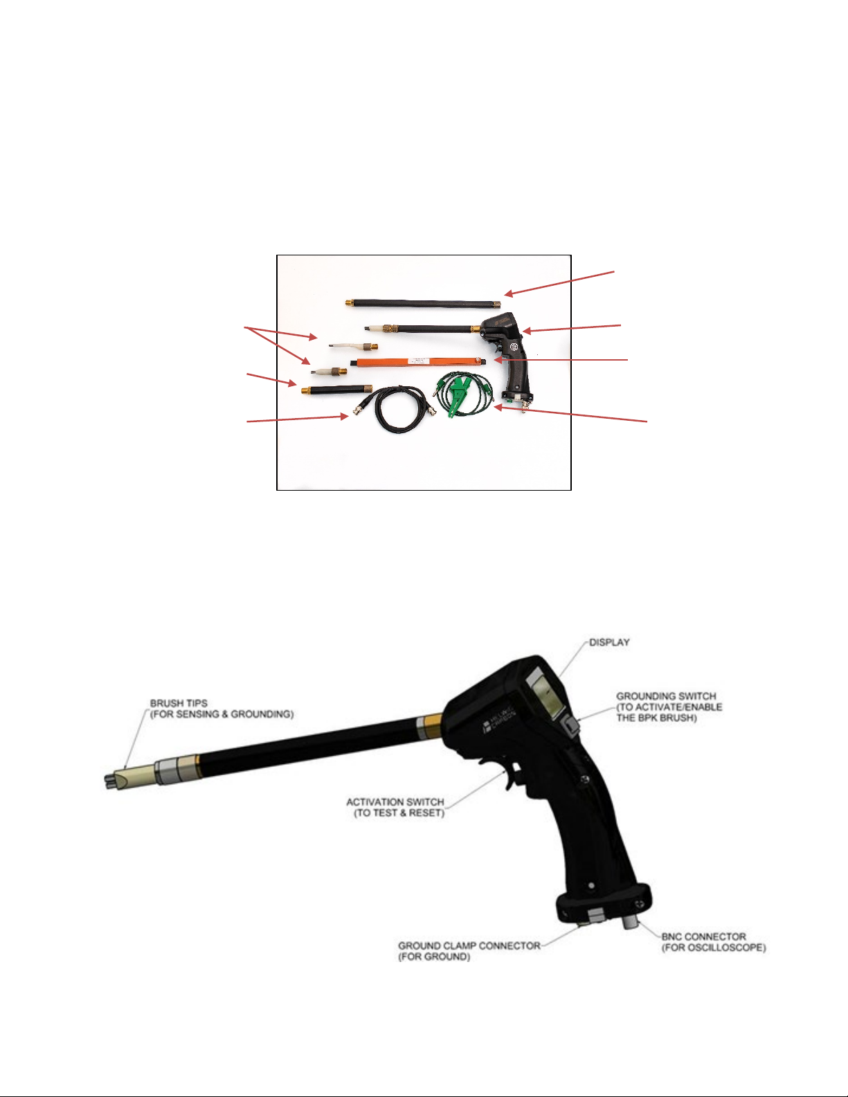
Components
BPK Probe™ Assembly Features
4” Extension Tube
Spare Tips
BNC Cable
Ground Wire &
Clamp
Probe Preparation Tool
BPK Probe™ Assembly
12” Extension Tube
Page 4 of 8 BPPI 6.19
BPK Probe™ Instructions for Use
Step 1: Prepare the BPK Probe™
Follow all safety precautions when working with rotating equipment.
The BPK Probe™ comes with a variety of tips and accessories. The assembly comes with the
6” extension tube and standard tip already mounted. Different extension tubes and tips can be
quickly and easily changed. In addition, the BPK Probe™ assembly has a BNC connector and
cable for connecting an oscilloscope if needed.
a) Verify the motor shaft contact area is clear of debris, oils and contamination.
b) Using the rubber flap side of the Probe Preparation Tool (Figure 3), identify a contact area
on the shaft for measurements.
c) Verify the contact area is clean and not in line with a key, keyway, set screw, or anything
that can obstruct or damage the sensor tip brushes.
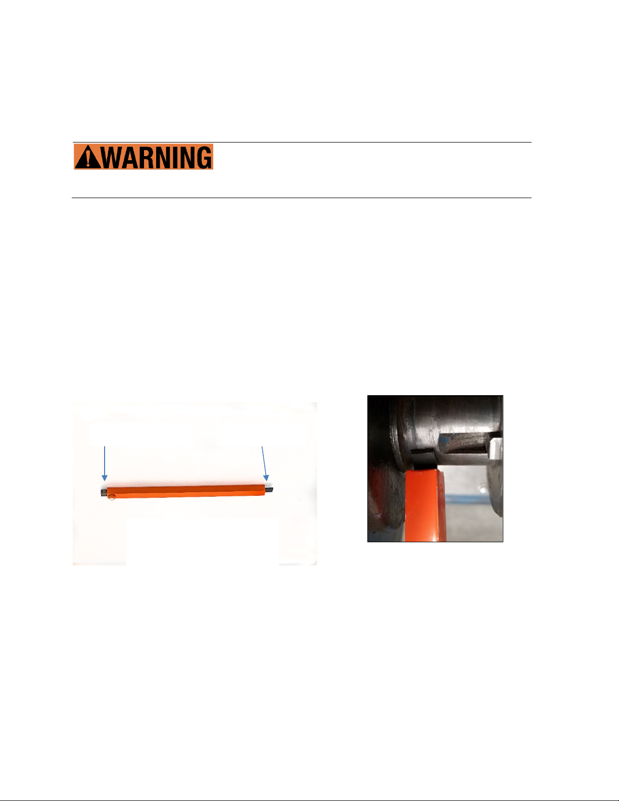
d) If required, use the Probe Preparation Tool’s cleaning stone (Figure 3) to remove rust,
debris, and oil from from the contact area (Figure 4).
e) Select the best tube and tip for your application.
Figure 4: Use the Probe Preparation
Tool’s cleaning stone to clean contact
area.
Figure 3: The Probe Preparation Tool
has two ends
: a cleaning stone to
clean the shaft surface and a
rubber
flap to detect for keyways.
Cleaning Stone
Rubber Flap
Page 5 of 8 BPPI 6.19
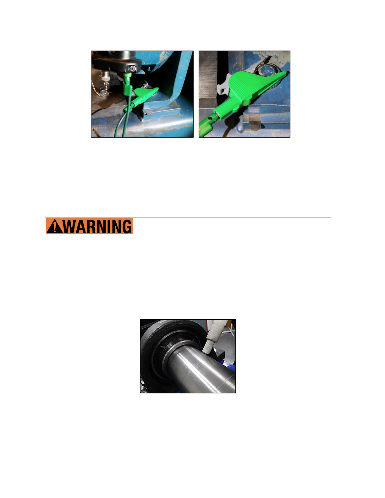
f) Attach the ground wire to the BPK Probe™ (Figure 5).Locate a clean, paint-free ground
source and secure the ground clamp (Figure 6).
g) Ensure the ground or optional BNC cable cannot be entangled with rotating or stationary
equipment, guards, etc.
Step 2: Test Motor Shaft Voltage
Follow all safety precautions when working with rotating equipment.
a) With the ground clamp safely secured, verify the rocker switch is off (LED not lit). This
disables the embedded grounding brush.
b) Remove the protective sensor tip cover and keep nearby.
c) On a suitable and properly prepared surface, carefully place the sensor tip against the
rotating shaft (Figure 7).
d) Ensure both sensor tip brushes are firmly and squarely against the contact surface.
e) Press the probe tip onto the shaft until about 1/8” of the spring-loaded brushes are exposed.
Figure 5: Attach ground wire to probe.
Figure 6: Locate a ground source
and secure the ground clamp.
Figure 7: Place the sensor tip against
the rotating shaft.

Page 6 of 8 BPPI 6.19
f) Perform the test. With the BPK Probe™ brushes pressed against the motor shaft, press and
hold the trigger switch throughout the test. As the test starts, the Helwig Carbon logo will
show (Figure 8).
g) Next, a SAMPLING SHAFT VOLTAGE message will appear (Figure 9). Continue to hold the
trigger switch with the tip of the probe against the motor shaft. When complete, the screen
will show a real-time test result (Figure 10).
h) Carefully remove the probe from the motor shaft, note the results, and release the trigger.
Remove the ground clamp and replace the protective tip cover. The test is complete.
i) The shaft voltage test can be repeated with and without
engaging the embedded grounding brush. To enable the
grounding brush, press the rocker switch on the face of the
probe handle. The embedded grounding brush is enabled
when the green LED on the switch is lit. Testing with the
grounding switch enabled shows the effectiveness of the
Helwig grounding solution (Figure 11).
Figure 8: As the test starts, the Helwig
Carbon logo will show.
Figure 9: A SAMPLING SHAFT
VOLTAGE message will appear.
Figure 10: Test results for unprotected
motor
.
Figure 11: Test results with
grounding switch enabled.

Page 7 of 8 BPPI 6.19
Step 3: Battery Status and Replacement
a) The BPK Probe™ is powered by a 9v battery. To check battery status, press and release
the probe trigger. The display will show the Helwig Carbon logo and then go to a ready
screen. The battery status will appear in the upper right corner of this screen (Figure 12).
b) If the battery is too low to operate the probe, you will get a flashing LOW BATTERY
message (Figure 13). The probe will not allow testing until the battery is changed.
c) To change the battery, loosen the retaining screw on the bottom of the probe handle (Figure
14). Remove the battery cover plate and slide the battery from the probe handle. Replace
battery (Figure 15). Insert cover plate and tighten the retaining screw.
Figure 12: Battery status in
upper right corner
.
Figure 13: LOW BATTERY
message
.
Figure 14: Loosen retaining
screw and remove cover plate.
Figure 15: Replace battery.

Page 8 of 8 BPPI 6.19
BPK-Probe Accessory Part Numbers
Item
Part Number
Description
1
P2017.01.07
PROBE PREPARATION TOOL
2
BKCT2392A-5-ND
GROUND CLAMP
3
501-1377-ND
GROUND WIRE
4
ACX1813-ND
BNC CABLE
5
PTE.04
PROBE TIP EXTENSION, 4"
6
PTE.06
PROBE TIP EXTENSION, 6"
7
PTE.12
PROBE TIP EXTENSION, 12"
8
PT.01
PROBE TIP ASSEMBLY, STANDARD
9
PT.T01
THIN PROBE TIP ASSEMBLY
10
10181262027702
REPLACEMENT BRUSH TIPS
Table of contents
Other HELWIG CARBON Measuring Instrument manuals

Popular Measuring Instrument manuals by other brands


Keithley
Keithley 616 instruction manual

RR Mechatronics
RR Mechatronics STARRSED TL Instructions for use

ASELSAN
ASELSAN STC-8250A Operation manuals

Keysight Technologies
Keysight Technologies MXA Series Installation note

Endress+Hauser
Endress+Hauser Prosonic M FMU40 Brief operating instructions

Adash
Adash A3716 user manual


