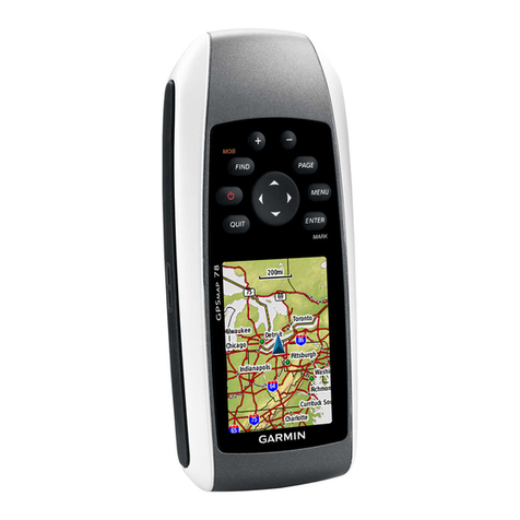
Hemisphere GPS eDriveTC User manual

Outback eDrive
User Guide
Part No. 875-0171 Rev. C1

This device complies with Part 15 of the FCC rules. Operation is subject to the following
two conditions:
• This device may not cause harmful interference.
• This device must accept any interference received, including interference, that may
cause undesired operation.
Copyright Notice
Hemisphere GPS Precision GPS Applications
Copyright © Hemisphere GPS (2007). All rights reserved.
No part of this manual may be reproduced, transmitted, transcribed, stored in a retrieval
system or translated into any language or computer language, in any form or by any
means, electronic, mechanical, magnetic, optical, chemical, manual or otherwise, without
the prior written permission of Hemisphere GPS.
Trademarks
Hemisphere GPS and the Hemisphere GPS logo, Satloc and the Satloc logo, and Mapstar,
Air Star Outback Guidance and eDrive are trademarks of Hemisphere GPS. Other
trademarks are the properties of their respective owners.
Notice to Customers
Contact your local dealer for technical assistance. To find the authorized dealer near you,
call or write us at:
Footnotes: OUTBACK™, OUTBACK Guidance®, OUTBACK Guidance Center™, OUTBACK
S™, OUTBACK S Lite ™, OUTBACK 360™. OUTBACK Steering Guide™, OUTBACK
Hitch™, eDrive®, eDriveTC™, Just Let Go™ and BaseLineHD™ are proprietary
trademarks of Hemisphere GPS, Inc. The OUTBACK S™ and S Lite ™automated
navigation and steering guide system is protected under U.S. Patents No. 6,539,303 and
No. 6,711,501. The OUTBACK Hitch™ automated hitch control system is protected under
U.S. Patent No. 6,631,916. The OUTBACK eDriveTC™ GPS assisted steering system is
protected under U.S. Patent No. 7,142,956. Other U.S. and international patents pending.
Outback Guidance
Hemisphere GPS
2207 Iowa Street
Hiawatha, KS 66434
USA
Telephone number:
Fax number:
E-mail address:
(800) 247-3808
(785) 742-4584
outbacksales@outbackguidance.com
www.hemispheregps.com


Warranty Notice
Covered Products
This warranty covers all products manufactured by Hemisphere GPS (the "Products").
Hemisphere GPS Limited Warranty
Hemisphere GPS hereby warrants solely to the end purchaser of the Products, subject to the exclusions and
procedures set forth herein below, that the Products sold to such end purchaser shall be free, under normal use and
maintenance, from defects in material and workmanship for a period of 12 months from delivery to such end
purchaser. Repairs and replacement components are warranted, subject to the exclusions and procedures set forth
below, to be free, under normal use and maintenance, from defects in material and workmanship for 90 days from
performance or delivery, or for the balance of the original warranty period, whichever is greater.
Purchaser's Exclusive Remedy
The end purchaser's exclusive remedy under this warranty shall be limited to the repair or replacement, at the option
of Hemisphere GPS, of any defective Products or components thereof. The end user shall notify Hemisphere GPS or
a Hemisphere GPS approved service center immediately of any claimed defect. Repairs shall be made through a
Hemisphere GPS approved service center only.
Exclusions
Hemisphere GPS does not warrant damage occurring in transit or due to misuse, abuse, improper installation,
neglect, lightning (or other electrical discharge) or fresh/salt water immersion of Products. Repair, modification or
service of Hemisphere GPS products by any party other than a Hemisphere GPS approved service center shall render
this warranty null and void. Hemisphere GPS does not warrant claims asserted after the end of the warranty period.
Hemisphere GPS does not warrant or guarantee the precision or accuracy of positions obtained when using
Products. Products are not intended for primary navigation or for use in safety of life applications. The potential
accuracy of Products as stated in Hemisphere GPS literature and/or Product specifications serves to provide only an
estimate of achievable accuracy based on:
• Specifications provided by the US Department of Defense for GPS Positioning,
• DGPS service provider performance specifications.
Hemisphere GPS reserves the right to modify Products without any obligation to notify, supply or install any
improvements or alterations to existing Products.
No Other Warranties
THE FOREGOING WARRANTY IS EXCLUSIVE OF ALL OTHER WARRANTIES, WHETHER WRITTEN, ORAL, IMPLIED OR ARISING BY STATUTE,
COURSE OF DEALING OR TRADE USAGE, IN CONNECTION WITH THE DESIGN, SALE, INSTALLATION, SERVICE OR USE OF ANY PRODUCTS
OR ANY COMPONENTS THEREOF, INCLUDING, BUT NOT LIMITED TO, ANY WARRANTY OF MERCHANT ABILITY OR FITNESS FOR A
PARTICULAR PURPOSE.
Limitation of Liability
THE EXTENT OF HEMISPHERE GPS’ LIABILITY FOR DAMAGES OF ANY NATURE TO THE END PURCHASER OR ANY OTHER PERSON OR
ENTITY WHETHER IN CONTRACT OR TORT AND WHETHER TO PERSONS OR PROPERTY SHALL IN NO CASE EXCEED, THE AGGREGATE, THE
COST OF CORRECTING THE DEFECTIVE ITEM. INNO EVENT WILL HEMISPHERE GPS BE LIABLE FOR ANY LOSS OF PROFITS, LOSS OF USE
OR FOR ANY SPECIAL, INDIRECT, INCIDENTAL, CONSEQUENTIAL OR CONTINGENT DAMAGES, EVEN IF HEMISPHERE GPS HAS BEEN
ADVISED OF THE POSSIBILITY OF SUCH DAMAGES. WITHOUT LIMITING THE FOREGOING, HEMISPHERE GPS SHALL NOT BE LIABLE FOR
ANY DAMAGES OF ANY KIND RESULTING FROM INSTALLATION, USE, QUALITY, PERFORMANCE OR ACCURACY OF ANY PRODUCTS.
Governing Legislation
To the greatest extent possible, this warranty shall be governed by the laws of the State of Arizona. In the event that
any provision hereof is held to be invalid by a court of competent jurisdiction, such provision shall be severed from
this warranty and the remaining provisions shall remain in full force and effect.

Obtaining Warranty Service
In order to obtain warranty service, the end purchaser must bring the Product to a Hemisphere GPS approved service
center along with the end purchaser's proof of purchase. For any questions regarding warranty service or to obtain
information regarding the location of any of Hemisphere GPS' approved service centers, contact Hemisphere GPS at
the following address:
Outback Guidance Technical Support
Hemisphere GPS
2207 Iowa Street
Hiawatha, Kansas 66434
USA
Phone 800.247.3808 Fax 785.742.4584
outbackcs@outbackguidance.com
http://www.hemispheregps.com

eDriveTC User Guide
i
Table of Contents
1: Overview . . . . . . . . . . . . . . . . . . . . . . . . 1
Product Overview . . . . . . . . . . . . . . . . . . . . . . . . .2
What’s Included . . . . . . . . . . . . . . . . . . . . . . . . . .3
Parts Listing . . . . . . . . . . . . . . . . . . . . . . . . . . . . .4
2: Getting Started . . . . . . . . . . . . . . . . . . . 7
Overview . . . . . . . . . . . . . . . . . . . . . . . . . . . . . . .8
Installing the eDriveTC 8
Powering the Unit . . . . . . . . . . . . . . . . . . . . . . .15
To power up both units 15
To power up the Outback S2 only 15
System Configuration . . . . . . . . . . . . . . . . . . . .16
Using the menu 16
Initial system startup sequence 16
3: eDriveTC Operation . . . . . . . . . . . . . . . 23
Guidance overview . . . . . . . . . . . . . . . . . . . . . . .24
General Operation 24
For Straight Driving 25

ii
For Contour Driving 26
Auto-Disengage . . . . . . . . . . . . . . . . . . . . . . . . .27
Manual Disengage . . . . . . . . . . . . . . . . . . . . . . .28
Auto-Engage . . . . . . . . . . . . . . . . . . . . . . . . . . . .29
4: Troubleshooting . . . . . . . . . . . . . . . . . . 31
Fine-Tuning Performance . . . . . . . . . . . . . . . . . .32
TroubleShooting Tips . . . . . . . . . . . . . . . . . . . . .34
Vehicle Type Setup Table . . . . . . . . . . . . . . . . . .35
Appendices . . . . . . . . . . . . . . . . . . . . . . . 37
A: Making the Most of Automated Steering . . .38
GPS Signal Accuracy 38
Machine / Vehicle Control 41
Implement Tracking 43
Field Conditions 45
Consistent Accuracy and Increased Productivity 46
B: Frequently Asked Questions . . . . . . . . . . . . .47

eDriveTC User Guide
iii
C: Sales and Service Information . . . . . . . . . . . .51
Contacting the Factory 51
Outback eDriveTC Extended Service Plan (ESP)
Summary 53
Limited Outback eDriveTC Extended Service Plan 54

iv

1: Overview
Product Overview
What’s Included
Parts Listing

2
1: Overview
Product Overview
Congratulations on the purchase of an Outback eDriveTC®. The Outback
eDriveTC GPS assisted steering system extends the functionality of the
Outback Guidance®system. The eDriveTC electronic components have been
designed to work with a wide range of agricultural equipment and
applications. A series of equipment specific kits have been developed with
the necessary components and detailed instructions to install the eDriveTC
on specific equipment models. A complete system consists of an
Outback S2TM (sold separately), an equipment model specific eDriveTC
install kit, and the eDriveTC electronic components. This manual covers the
installation of the electronic components along with the eDriveTC setup and
operation.
Note: The equipment model specific kit should be installed first.
Please refer to the instructions included with the model specific kit
prior to completing the electronic installation and setup.
Note: This manual covers the eDriveTC installation and operation
with the S2.

eDriveTC User Guide
3
What’s Included
The following equipment is included with the Outback eDriveTC:
• eDriveTC console
• CAN/Power cable
• CAN/Expansion cable
• CAN/Battery cable
• Auxiliary power cable
• Tie straps
• Screws (#8 x 3/4”)
Figure 1-1. Outback eDriveTC and Equipment

4
1: Overview
Parts Listing

eDriveTC User Guide
5
Table 1-1: Outback eDriveTC Guidance System
Ref. P/N Description Qty.
1 Outback S2 (required)
2 Outback External CAN Device (optional)
3 051-0101-001# CAN/Power Cable, OKB-eDriveTC - 10ft Lg/15ft Lg, WP 1
4 051-0067-005# CAN/Expansion Cable, OBK-eDriveTC - 10ft 1
5 054-0065-000# CAN/Battery Cable, OBK-eDriveTC - 5ft Lg. 1
6 806-1007-03A Console, OBK-eDriveTC 1
7 054-0044-003# Auxiliary Power Cable, OBK-eDriveTC - 12ft Lg. 1
8 677-2002 Tie Strap, #7 - Releasable 12
675-1138-000 SCR, #8-18 x 3/4”, SD, HEX COMBO, ZP 2
485-1154 Decal, “Outback Equipped” - reverse printed 1

6
1: Overview

2: Getting Started
Overview
Installing the eDriveTC
Powering the Unit
System Configuration

8
2: Getting Started
Overview
Before using the Outback eDriveTC for the first time, you’ll need to:
• install the eDriveTC
• turn on the power,
• and set basic features.
Installing the eDriveTC
Exchange Power Cable - If the power cable currently used with the
S2 does not have a second CAN connector then it will need to be
replaced by the CAN/Power cable in the eDriveTC package. If the current
power cable used with the S2 has a second CAN connector then
proceed to the next page.
1. Loc ate t he C AN /Powe r
cable in the eDriveTC
package.
2. Install the right angle
connector into the
Outback S2 CAN/Power
port as shown.
3. Twist the connector
firmly until it locks into
place.
4. Secure the CAN/Power
cable and antenna
cable back to the console mounting base with tie straps to provide
strain relief.
CAN/Power Cable

eDriveTC User Guide
9
Daisy Chain Power Cable - Install an optional Outback external CAN
device, using the instruction booklet provided.
1. Loc ate t he
CAN/
Expansion
cable in the
eDriveTC
package.
2. Disconnect
the CAN
connector
from the
external CAN
device and insert the ‘Y’ end of the CAN expansion cable as shown.
3. Twist connectors firmly until they lock into place.
4. Secure the cables to the console mounting base with tie straps to
provide strain relief.
Note: The Outback eDriveTC may also be used in combination
with an optional Outback external CAN device (example:
Outback 360.) If an external CAN device is already installed, it is
not necessary to exchange the power cable. Instead, a three-
connector CAN/Expansion cable is installed between the
external CAN device and the eDriveTC.
CAN/Expansion Cable

10
2: Getting Started
Connect Cables To Battery -
1. Loc ate t he
Auxiliary Power
cable in the
eDriveTC package.
It has a 2-pin
round connector
on one end and a
pair of ring
terminals on the
other.
2. Locate the short
CAN/Battery cable.
It has a 2-pin flat connector on one end and a pair of ring terminals
on the other.
3. Connect the ring terminal ends of both cables directly to the
battery. The red wire goes to the positive terminal, and the black
wire goes to the negative.
4. Route both cables into the cab, securing with tie straps. Avoid
sharp edges and pinch points which could damage the cables and
cause a short circuit.
Note: Outback electronic components are designed for 12 volt
negative ground automotive systems. Make certain there are good
solid connections to 12 volts and ground. Connect the red wire to
positive(+) and the black wire to negative(-) or ground.
CAN/Battery Cable
Auxiliary Power Cable

eDriveTC User Guide
11
Connect CAN/Battery Cable: - Connect the CAN/Battery cable to the
CAN/Power cable.
Use this criteria when mounting the eDriveTC unit:
1. Securely mount the eDriveTC unit to the vehicle with screws on the
eDrive console flanges. (See Figure 2-2 on page 12.)
2. Have the top of the eDriveTC console face upwards according to
the “up” arrow on the console. (See Figure 2-2 on page 12.)
CAN/Power Cable
CAN/Battery Cable
This manual suits for next models
1
Table of contents
Other Hemisphere GPS GPS manuals

Hemisphere GPS
Hemisphere GPS XF2 User manual

Hemisphere GPS
Hemisphere GPS V104s User manual

Hemisphere GPS
Hemisphere GPS MBX-4 User manual

Hemisphere GPS
Hemisphere GPS LiteStar II Air User manual

Hemisphere GPS
Hemisphere GPS XF2 User manual

Hemisphere GPS
Hemisphere GPS LiteStar II Air User manual

Hemisphere GPS
Hemisphere GPS Outback GUIDANCE AutoMate 750-3007 User manual