hendor D90 Series User manual

Operation Guide for Hendor Pumps & Filters
1. Introduction
2. Receipt
3. Safety precautions
4. Installation / Operation and maintenance
4.1 Vertical pumps
4.2 Horizontal pumps
4.3 Filter chambers
5. EC declaration
6. Trouble shooting
7. Exploded view and Parts list
1. Introduction
Thank you for choosing this Hendor product. Before starting to use this product Hendor strongly recommends to read this operation guide
thoroughly and to follow instructions as closely as possible. In this way your product will function reliable for years to come. This operation
guide contains all obligatory safety precautions. It should be put at disposal of the end-user of this product and should be present at site
in order to allow operator and maintenance crew to use it.
General Risks
Electricity
Electricity is a potential risk. Even without direct contact to the power grip. Components can be electrically charged by its usage. This can
cause a local burn or even an injury by falling.
When operating the product make sure it is connected correctly . Check grounding and fuses for correct operation.
When applying maintenance make sure the product is disconnected from the power grid and static discharged.
Liquids
This product is intended to use in liquids of chemical nature. Be aware of possible spills and leakage. When installing this product it can
splash in the liquid and cause exposure to the chemicals.
These liquids could cause injury to personnel. Personnel should wear appropriate personal protective equipment at any time.
Weight and dimensions
This product has a certain weight and dimension which can destabilize a person. Make sure there is supervision during maintenance. A
person could be injured by fall or entrapment by lifting without the proper lifting tools.
Do take notications on local standards and safety regulations regarding these general risks.
© Hendor - Quality Pumps & Filters - 1 - Info 2016715/R0
Type
Hendor
Serial No.
ID Location

© Hendor - Quality Pumps & Filters - 2 - Info 2016715/R0
2. Receipt
At receipt of the product the identity of the product (by checking type plate data), the completeness of delivery as well as absence of visible
damage should be ascertained. The end-user or his representative must ascertain the match of material specication and specic liquid
used. Any problems arising from these checks should be made in writing and preferably signed by the forwarding agent as evidence.
3. Safety precautions
The presented symbols are safety alert symbols. Be alert to potential personal injury in case symbols on the product or in this manual
are shown.
This label warns for risk of electrical shock when failing to observe.
DANGER
This label warns about hazards that can cause personal injury, death or major property damage if ignored.
Keep in mind that the product can contain chemical liquids.
WARNING
Carefully read and follow all safety instructions in the manual and on the pump. Keep safety labels in good condition. Replace missing or
damaged safety labels. Maintain at all times the local rules and regulations for safe operations.
3.1 Installation
Pumps and lters should be connected in the prescribed way.
The user always has to consider personal safety and health for himself as well as his direct vicinity.
3.2 Electrical
1. Only qualied electricians are allowed to connect pumps according to local regulations of the power supplier.
2. Grounding of the motor should be applied rst; failure to ground can cause severe or fatal shock. Do not ground to gas
supply lines.
3. Before connecting the motor check corresponding voltage of motor and power supply. Incorrect connection can cause re
or serious damage to the motor and voids warranty. See wiring diagram.
4. Check if frequency of power supply corresponds with frequency on label of pump.
5. Avoid unexpected or accidental starting of the motor by disconnecting and locking out power supply.
6. In case of repair and maintenance disconnect and lock out power supply.
7. Do not point a jet of water at the motor to avoid personal injury (risk of electrical shock).
8. Check wiring dimensions according to the power of the motor.
9. Check fuses on the power supply connection.
10. Thermal overload switch should be used on the connection to the pump. The current overload is adjusted to the value of the
motor name plate including +10%.
11. To avoid damage, do not hoist the pump by the cord line.
12. Make sure the cord line is not jammed and avoid sharp edges.
13. General rule for Hendor pump shaft rotation: Always run clockwise (CW), looking at cooling fan side.
Direction of rotation is also indicated on the motor by arrow.
A PTC is standard provided in motors of vertical pumps as of 4kW. Two extra connection wires will be available inside the terminal
block. Hendor uses singular PTC’s with a thermal limit of 160°C. The PTC is color coded according to DIN 44081 / DIN 44082.
Do not apply any voltage to the PTC, use a assigned relays.
As of 4kW a PTC is available in vertical pumps, the warranty will expire on the motor if the PTC is not used.
!
U1 V1 W1
W2 U2 V2
U1 V1 W1
L1 L2 L3
W2 U2 V2
L1 L2 L3
r
I
N L
single phase3-phase
!

!
© Hendor - Quality Pumps & Filters - 3 - Info 2016715/R0
3.3 Checking direction of rotation
Vertical pumps: Always check the direction of rotation outside the liquid.
Horizontal pumps: Always check the direction of rotation ooded with liquid.
Briey switching on the power will show direction of rotation, looking at cooling fan side. Ignoring these recommendations could
damage the pump severely.
3.4 Plumbing
1. Connections to the pump and lter should be provided with reliable, persistent and chemical resistant materials.
2. Where hoses are used, take care of using correct hose clamps.
3. Use the right elastomers when making the connections.
4. Pipes and hoses should be internally cleared of any obstructions.
5. Check tightness of connections to prevent leakage and spills before starting up.
6. Thermoplastic pump components do not tolerate any plumbing stress.
7. Plumbing should be properly aligned and supported to prevent distortion and damage of parts.
8. Leave enough space around the pump or lter for easy access and maintenance.
9. Keep location of the pump away from any heaters or heater coils.
10. Pumps and lters should be mounted on a sturdy base.
3.5 Polution
Solids and mud are harmful for pumps. There are suitable strainers available to keep these substances out of the pump.
4.1 Vertical pumps
4.1.1 Installation
Take notice of enough bottom clearance at the suction side of vertical pumps.
See recommendations for bottom clearance.
Hendor vertical pumps are designed for in-tank installation.
Out-of-tank models are optional and require special installation instructions.
Ensure that the pump is connected correct to the power supply and
that the plumbing is tted leakfree.
1 maximum liquid level
2 normal working level
3 minimum starting level
4 pump A stops pumping
5 pump B will continue to work
(if it is not switched off)
6 pump B stops pumping
7 bottom tank
4.1.2 Operation and maintenance
At start up the pump should be checked for direction of rotation OUTSIDE the liquid (see label on pump).
Contaminated strainers (if mounted) can reduce performance and should be cleaned regularly.
Regular pump inspection
During operation all pumps should be checked regularly. Check ow, pressure, manometer indication, pipe work, hoses, hose clamps and
absorbed power by monitoring amperage of the motor. Pumps should be tted with thermal overload switch. Check pumps for any unusual
noise or vibration (this may indicate the moment of maintenance).
Maintenance precautions
To avoid dangerous or fatal electric shock hazard and to avoid injury from starting the motor unexpectedly, disconnect and lock
out power supply to the motor. Always use genuine parts to assure good performance. When taking pump apart check for
sequence of disassembly and reassembly. After having completed maintenance or repair, follow safety and installation
instructions.
4.1.3 Dismantling and reassembly
For efcient maintenance of Hendor vertical pumps, some special tools are available (see page 5).
General precautions prior to dismantling
- always disconnect electric cables.
- disconnect discharge pipe.
- clean pump and remove remaining liquid in pump housing.
- do work on a clean bench.
When ordering Hendor parts always quote serial number, pump type and drawing position number of the required part.
!
Type Minimum bottom
distance (mm)
D90 50
D110 55
D120 55
D160 25..100
D18 65
D20 100
D24 100
Immersion
length
(mm)
Suction
extension
BA
1
2
3
4
5
6
7
max.
min.

© Hendor - Quality Pumps & Filters - 4 - Info 2016715/R0
Dismantling
Series D90
- remove drip cover (if applicable).
- remove fan cover.
- remove cooling fan by applying two screwdrivers.
- remove sealing ring and locking ring.
- turn pump upside down.
- remove volute cover (turning clockwise).
- secure shaft end against rotation and loosen impeller (turning anti-clockwise) by using impeller key.
- take off wiring casing of motor by removing 3 bolts; mind not to damage stator wiring!
- unscrew 4 screws that are accessible for removing pump house.
- take off pump house.
- loosen shaft protection pipe (turning anti-clockwise).
Series D110
- remove drip cover (if applicable).
- remove fan cover.
- remove cooling fan by applying two screwdrivers.
- remove sealing ring and locking ring.
- turn pump upside down.
- remove volute cover (turning clockwise).
- secure shaft end against rotation and loosen impeller (turning anti-clockwise) by using impeller key.
- remove bolts/nuts that connect motor to pump housing.
- take off pump housing completely.
- loosen impeller-shaft protection pipe (turning anti-clockwise).
Series D120
- remove drip cover (if applicable).
- remove fan cover.
- remove cooling fan by applying two screwdrivers.
- remove sealing ring and locking ring.
- turn pump upside down.
- remove volute cover (turning clockwise).
- secure shaft end against rotation and remove impeller (turning anti-clockwise) with impeller key.
- unscrew 6 screws that are accessible for removing pump house.
- take off pump house.
- loosen shaft protection pipe (turning anti-clockwise).
Series D160
- remove drip cover (if applicable).
- remove fan cover.
- remove cooling fan by applying two screwdrivers.
- remove sealing ring and locking ring.
- turn pump upside down.
- remove 5 bolts and remove volute cover.
- remove impeller screw 205 (turning anti-clockwise).
- secure shaft end against rotation and remove impeller (turning anti-clockwise) with impeller key.
- remove 4 bolts/nuts that are accessible for removing pump house.
- take off pump house.
- in case thrustring is worn, take out the ring by using special tool and turn clockwise.
Series D18
- remove drip cover (if applicable).
- remove fan cover.
- remove cooling fan by applying two screwdrivers.
- remove volute cover (turning clockwise).
- secure shaft end against rotation and remove impeller (turning anti-clockwise) with impeller key.
- remove bolts/nuts that connect motor to pump assembly
Series D20 - D24
- remove drip cover (if applicable).
- remove fan cover.
- remove cooling fan by applying two screwdrivers.
- remove volute cover (turning clockwise).
- secure shaft end against rotation and remove impeller lock bolt cover.
- remove M8 bolt to unlock impeller.
- remove M8 stud with hexagon key.
- remove impeller by screwing (clock wise) with M10x70 steel bolt.
- remove bolts/nuts that connect motor to pump assembly

© Hendor - Quality Pumps & Filters - 5 - Info 2016715/R0
Electric Motor
All motors are tted with standard ball bearings.
- by removing rear-end and front-end cover, bearings are accessible.
- rear bearing can be taken off by standard puller.
- front bearing is only accessible after taking out spring ring and removing front shield (for easy removal, heat the front shield).
front bearing of vertical pump motors can only be taken off by applying special Hendor bearing puller.
Replacing worn or damaged parts
Dismounting and retting should be carried out very carefully.
Assembling motor is done in reverse order
Ensure free rotation and check concentricity of the shaft of vertical pumps at 0,03 mm maximum.
Assembly
- ret all parts in reverse order.
- prior to mounting volute cover measure distance between top of impeller and bottom of volute cover; this dimension should be
in range of 1-2 mm.
Handle pump as a new installation (see page 2 and 3).
Prior to operation of the pump check direction of rotation as indicated by arrow on the motor.
Motor shaft rotation is clockwise, viewed from top of the motor. Testing the rotation of the shaft has to be done outside the liquid;
running the pump backwards may loosen the impeller and damage the pump.
Special tools
Tool For disassembly of Use Pump type Article number
1 Strap wrench Suction extension pipe Strap wrench All types 9999-000-000-037
(if applicable)
2 Grip Strainer (if applicable)
Flat strainer Grip D18 9011-000-001-499
Pump house cover
3 Radius key High strainer Radius key All types 9062-600-999-002
4 Grip Pump house cover Grip D9*/D110/D12* 9011-000-001-551
Impeller
5 Pen key Pump house cover Pen key D20/D24 9063-623-100-250
6 Grip Impeller Grip D18 9011-000-001-499
Impeller key D18 9011-891-001-080
7 Wrench+bit Motor T-wrench and Toolbit M4 0,12 - 0,18 - 0,25 kW 9999-000-000-020
T-wrench and Toolbit M5 0,37 .. 2,2 kW 9999-000-000-021
T-wrench and Toolbit M6 3 .. 9 kW 9999-000-000-047
8 Bearing puller Motor bearings Complete bearing puller set All types 9999-000-000-031
Bearing puller D9* only 9999-000-000-023
Bearing puller D110 only 9999-000-000-024
Bearing puller D12*/D18/D20/D24 only 9999-000-000-025
9 Radius key Thrustring Radius key (bended) D16* 9062-600-999-003
10 Wrench Union nut Wrench All types
10 PU Paint 0.25L tin (RAL 1011) All motors 9999-000-000-041
© Hendor - Quality Pumps & Filters - 6 - Info 2016715/R0
4.2 Horizontal Pumps
4.2.1 Installation
Horizontal magnetic drive & seal pumps are very sensitive to suction conditions. Often pump problems are caused by poor suction
conditions. The bigger the pump and the higher the temperature, the more important the general hydraulic guidelines should be applied.
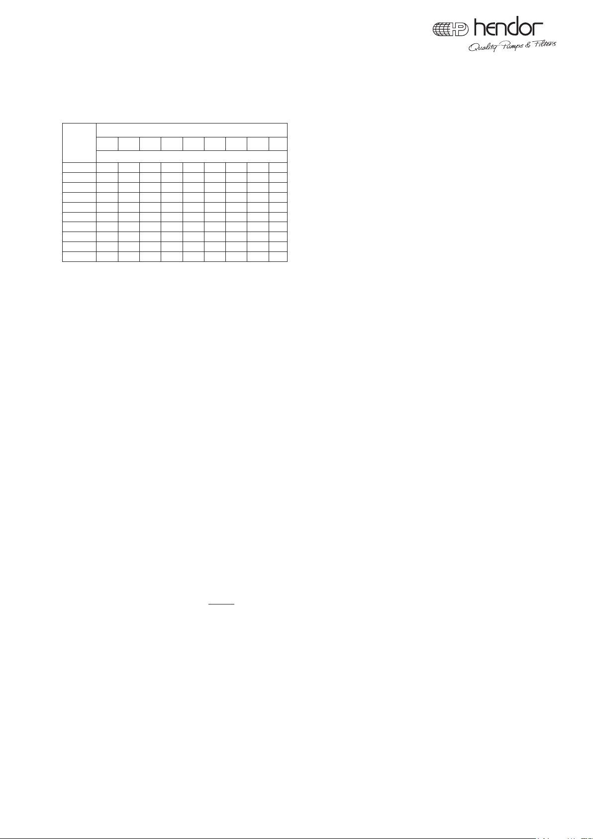
Always try to respect the basic rules for liquid velocity v (m/s) and NPSH.
We recommend for Suction side v = 1 - 2 m/s; Discharge side v = 1,5 - 3 m/s
Flow (l/h) Inner pipe diameter (mm)
15 20 25 32 40 50 65 80 100
Velocity (m/s) at given ow (l/h)
1000 1,57 0,88 0,57
2000 3,15 1,77 1,13 0,69
4000 6,29 3,54 2,26 1,38 0,88
6000 5,31 3,4 2,07 1,33
8000 4,53 2,76 1,77 1,13
10000 5,66 3,46 2,21 1,42 0,84
15000 5,18 3,32 2,12 1,26 0,83
20000 6,91 4,42 2,83 1,68 1,11
30000 10,4 6,63 4,25 2,51 1,66 1,1
40000 8,85 5,66 3,35 2,21 1,4
Golden rules for proper pipe work
1. Keep suction pipe as short as possible.
2. Increase pipe size on suction side by at least one pipe diameter for longer suction pipe and/or higher temperature.
3. Use eccentric adaptors at varying diameters to prevent air pockets.
4. Avoid elbows, bends and ttings at suction side. When unavoidable keep ttings at a distance of 10 times pipe diameter away
from pump inlet.
5. Pipe work should slope up towards pump to prevent air pockets.
6. Pipe work should be completely leak free.
7. Support pipe work near to pump to prevent stress on plumbing.
8. Allow sufcient liquid level to prevent air intake on suction side.
9. Use generously oversized strainer in case of foreign particles.
10. Use siphon breaker when priming over top of tank.
11. Never throttle pump on suction side.
12. In case of doubt consult Hendor for proper sizing and NPSH calculation.
4.2.2 Operation and maintenance
Magnetic drive pumps. How it works?
Driver (motor) and impeller (driven) are physically separated by a shell.
Pump part (wet end) is completely sealed and therefore isolated from plating proces.
Power transmission is established by magnetic force between motor shaft and impeller.
Bearings are lubricated and cooled by liquid itself.
Mechanical seal pumps. How it works?
Impeller is directly attached to the motor shaft by shaft coupling.
Mechanical seal on pump shaft prevents liquid from coming out.
Mechanical seal is lubricated and cooled by liquid itself.
These type of pumps are not self priming and not designed to run dry or hot. Optional priming chambers and dry run protection devices
are available.
Initial start-up
Priming instructions at ooded suction:
1. Open all valves on suction and discharge side.
2. The pump should always be ooded with liquid to prevent any damage on bearings.
3. These type of pumps are not self priming. Therefore liquid level in the bath should be ample above entrance level of the pump.
4. Check for direction of rotation before start-up by shortly switching on/off.
5. Start the pump when no air remains in the pump.
6. When pumping liquid with higher density than water, start up with almost closed discharge valve to reduce power consumption.
Priming instructions at non ooded suction:
1. Ensure entrance of suction pipe is in liquid.
2. Slowly ll pump casing and suction pipe. Use discharge connection to ll.
3. Check if pump is free of air.
4. Close discharge valve and check for direction of rotation before start-up by shortly switching on/off.
5. Start the pump.
6. Wait until pump is building up pressure, and slowly open discharge valve.
Restart after power failure: Check if the pump is able to prime again. Suction pipe and pump housing should be lled.
Contaminated strainers (if applicable) can reduce ow, therefore: clean strainers regular.

© Hendor - Quality Pumps & Filters - 7 - Info 2016715/R0
Regular pump inspection
During operation all pumps should be checked regularly. Check ow, pressure, manometer indication, pipe work, hoses, hose clamps and
absorbed power by monitoring amperage of the motor. Pumps should be tted with thermal overload switch. Check pumps for any unusual
noise or vibration (this may indicate the moment of maintenance).
Maintenance precautions
To avoid dangerous or fatal electric shock hazard and to avoid injury from starting the motor unexpectedly, disconnect and lock
out power supply to the motor. Always use genuine parts to assure good performance. When taking pump apart check for
sequence of disassembly and reassembly. After having completed maintenance or repair, follow safety and installation
instructions.
Recommended maintenance schedule
The recommended maintenance schedule depends upon the nature of the uid being pumped and the specic application. If the pump is
used in a clean uid, it is recommended that the pump be removed from service and examined after six months of operation or after 1500
hours of operation. If the pump is used on uids with solids, high temperatures or other items that could cause accelerated wear, then this
initial examination should be sooner.
After the initial examination of the internal components and wear items are measured, a specic maintenance schedule can be determined.
For best results, it is recommended that the pump be removed from service annually for examination.
new: 3,5
min.*3,2
new: 3,5
min.*3,2
MX40..120 (108)
MX40..120 (107)
M110..400 (108)
MX160..410 (108)
M110..400 (107)
MX160..410 (107)
* Minimum value should not be exceeded in use
Wear dimensions of impeller bearings
new: 4
min.*3,7
new: 4
min.*3,7
new: Ø19,8
min.*19,5
new: Ø41,8
min.*41,5
Ø54
Ø32
M12x1.5 left
Ø45
Ø80
new: Ø33,8
min.*33,5
new: Ø64,7
min.*64,4
M25x1.5 left
M50x1.5 right M35x1.5 right

© Hendor - Quality Pumps & Filters - 8 - Info 2016715/R0
4.2.3 Dismantling and reassembly
4.2.3.1 Magnetic drive pumps
General precautions prior to dismantling
- always drain liquid from pump.
- disconnect all necessary electric cables or use switch on pump.
- disconnect suction and discharge piping (watch spilling liquid).
- do work on a clean bench.
When ordering Hendor parts always quote serial number, pump type and drawing position number of the required part.
Dismantling
- remove bolts from pump casing.
- take out impeller and impeller shell; mind strong magnetic force
Replacing worn or damaged wet end parts
Series M10..M15
- take ceramic shaft out of casing and replace it.
- rotating bushing is molded into impeller; replacing only possible by exchanging complete impeller.
Series MX40..MX410 and M110..M400
- static bearings cannot be replaced (heat shrinked); when damaged replace complete part.
- rotating bearings are mounted by thread; front = right-handed thread (dismantling = turning CCW);
rear = left-handed thread (dismantling = turning CW).
General description of dismounting a drive magnet
- loosen hex. screws through hole in bracket.
- by means of a lever drive magnet down the shaft; mind strong magnetic force.
- check for remaining metal particles on the magnet and remove them.
General description of mounting a drive magnet
- slightly grease shaft of motor.
- replace drive magnet on shaft by hand watching position of key.
- ensure that drive magnet goes up to shaft end (when using a hammer, be sure motor bearings are not damaged).
- secure hex. screws.
Assembly
- mount impeller shell (check for free rotation by hand).
- put impeller into shell; mind strong magnetic force.
- place O-ring and put pump casing into place (outlet up).
- mount bolts and tighten them crosswise.
After assembly always check for free rotation by hand. Verify direction of rotation indicated by arrow on pump/motor prior to
regular operation.
Horizontal pumps: Always check the direction of rotation ooded with liquid.
Briey switching on the power will show direction of rotation, looking at cooling fan side. Ignoring these recommendations could damage
the pump severely.
4.2.3.2 Mechanical seal pumps S55 .. S300-PP
General precautions prior to dismantling
- always drain liquid from pump.
- disconnect electric cables or use switch on pump.
- disconnect suction and discharge piping.
- do work on a clean bench.
When ordering Hendor parts always quote serial number, pump type and drawing position number of the required part.
Dismantling
- remove bolts from pump casing.
- take off SS plate and pump casing.
- turn safety guard so that hex. screw on coupling is accessible.
- loosen front screw in coupling (pump side).
- take out impeller together with rotating parts of mechanical seal.
Replacing worn or damaged parts
- rear static seal ring is easy to replace; mind position of seal ring according to locking pin; always renew O-rings after removing parts.
- take off rotating part; mind position of coil and hook; at replacing seal ring do position O-ring, coil and hook.
!
!

© Hendor - Quality Pumps & Filters - 9 - Info 2016715/R0
Assembly
- put back cover including static seal ring in place against steel bracket; mind upright position of supply channel for seal.
- lubricate seal with a little detergent.
- place at rubber gasket in position.
- put a spacer (thickness 2 mm) between back cover (124) and steel bracket (103) (adjusting pre-load on seal).
- put impeller back into position; mind correct position of all rotating parts.
- push impeller rmly as far as possible; hold that position and secure front hex. screw in coupling.
- remove spacer from back cover.
- put pump casing and SS plate back into place.
- mount bolts and tighten them gradually.
- turn safety guard so that holes are pointing downwards (drain in case of leakage).
Handle pump as a new installation (see page 2).
After assembly always check for free rotation by hand. Verify direction of rotation indicated by arrow on pump/motor prior to
regular operation.
Horizontal pumps: Always check the direction of rotation ooded with liquid.
Briey switching on the power will show direction of rotation, looking at cooling fan side. Ignoring these recommendations could
damage the pump severely.
4.3 Filter chambers
4.3.1 Installation
Following rules should be respected when installing :
Bottom of lter chamber (by preference) is placed at the same height as bath level; this will ensure an easy medium change and prevents
unwanted emptying of tank.
1. Maximum pressure should not exceed indication on dial of manometer.
2. Maximum allowable pressure at temperature range is indicated on top of lter chamber.
3. Adjust diameter of in- and outlet of the lter to required capacity of the system.
4. Return pipe from lter chamber should be placed as far as possible from pump inlet in order to promote good bath movement.
5. Filter chamber 362 has a tiltable lid. Position of lid can be changed by positioning top ring (304).
4.3.2 Operation and Maintenance
Maximum pressure in lter chamber
The maximum pressure in Hendor lter chamber should not exceed the engraved value on top of the cover plate.
Pressure gauge
A pressure gauge is tted on most Hendor lter chambers. An anti-freeze lled chamber above a membrane separates the pressure
gauge from the process liquid. During normal operation the lter chamber regularly should be inspected for ow (dial indication on gauge).
If pressure on manometer is less than usual, the chamber below the manometer should be relled.
Topping up manometer liquid:
After removing gauge (328) and air release screw, top up casing (327) with anti-freeze.
When assembling gauge (mind O-ring 335) liquid must show up.
Put back air release screw into casing and tighten it.
If liquid does not show up repeat procedure here above. If still no liquid shows up the membrane should be replaced.
Remove gauge (328), unscrew 4 screws, take off the lid (327), replace membrane (326), ret 4 screws lightly, holding down the membrane
with unsharp object through lid, tighten 4 screws and repeat above mentioned procedure.
If pressure on the dial of the gauge is not coming back to zero, when the pump is switched off, there may exist a difference of pressure
between inside gauge and open air. To correct dial indication cut off the top of the rubber cap on top of the gauge.
4.3.3 Dismantling and reassembly
Replacement of lter elements
Depending on the type of lter, the lter element(s) should be exchanged reaching a maximum pressure difference of 1-2,5 bar.
Sequence of operation
- switch off pump (ensure pump cannot be started unexpectedly).
- close all main taps.
- open drain valve.
- open air release tap (turning CCW maximum 2 rotations) to empty lter chamber
- loosen all star buttons.
- remove or tilt the lid of the lter chamber; sometimes the gasket sticks to the chamber and extra lifting effort is required to
remove the lid.
Hendor lter chambers are equipped with cartridges, discs or bags.
After removing the contaminated lter medium it should be disposed off according to environmental guidelines.
Properly install the new lter medium to prevent by-pass of unltrated liquid.

Closing sequence
- check sealing rubber of chamber on distortion.
- close lid.
- tighten star buttons rmly crosswise.
- close drain valve, open main taps and start-up the pump.
- check unit for any leakage.
- after bleeding the unit, close air release tap.
Particular instructions series 362
- when loosening star buttons, two xed star buttons should be turned clockwise, which will slightly lift the lid (because of sticking
gasket) after removing other star buttons.
- after lifting, two star buttons have to be turned 4 times anti-clockwise in order to lift the lid by handgrip into leaning position.
Closing sequence
- check sealing rubber of chamber on distortion
- close lid by tilting down
- turn two xed star button 4 times clockwise
- tighten remaining star buttons rmly crosswise and at last two remaining xed star buttons.
- close drain valve, open main taps and start-up the pump.
5. EC-Declaration of conformity
Manufacturer: Hendor Pompen BV
Address: P.O. box 9
5530 AA Bladel
The Netherlands
Herewith we declare, that the product:
Pump
- is in conformity with the provisions of the Machinery Directive, as amended, and with national
implementing legislation (Directive 2006/42/EC second edition)
- is in conformity with the provisions of the following other EC directives: Low voltage directive (Directive 2014/35/EC)
Filter
- is in conformity with the provisions of the Pressure Equipment Directive PED97/23/EC
conformity assessment procedure: Module A
Conrmed at Bladel
Signature
Technical Director H.F.G. Bohncke
5.1 Warranty and Service-Support
1. The warranty on goods delivered by Hendor delivered for defects that are caused by manufacturing and/or materials errors is valid during
a period of a maximum of 8000 operating hours within 12 months after the delivery ex-factory by Hendor. Solely when as a consequence
of transport of the delivered goods to a destination outside Europe the putting into operation of the good does not take place immediately
after delivery, the aforementioned warranty period is extended with the duration of the transport, it being understood that the warranty
period in no case will be longer than 18 months from the delivery ex-factory. After expiry of this term any warranty becomes void.
Hendor is not liable and offers no warranty for defects that are not caused by manufacturing and/or materials errors. Each warrant
becomes forfeit if the defect is not reported in writing to Hendor within 14 days after discovery, albeit after it could reasonably have been
discovered, accompanied by a precise description of the complaint as well as the work conditions.
2. The warranty consists of replacement or repair of the defect product or parts thereof, such at the discretion of Hendor. All other costs that
must be made in connection with the replacement or repair, such as freight costs, import duties, possible costs of a service mechanic,
will be for the account of the counterparty. Products which are sent in connection with a warranty claim to Hendor, must be sent clean
and free of chemical residue and free of charge. Replacement or repair is executed in accordance with the directions of Hendor and in
the manner that it deems t. Replacement or repair shall solely be executed after permission in writing of Hendor.
3. Each warranty or liability of Hendor becomes void, if the aforementioned conditions are not complied with.
4. Warranty claims are furthermore excluded in any case if:
a) the products are used for an application not accepted in writing by Hendor or have been modied;
b) the products have not been used according to the technical manual or have been used incorrectly or inexpertly, have been
maintained insufciently or the damage or the defect is the consequence of normal wear and tear;
c) the counterparty does not comply with any obligation (nancially or otherwise) towards Hendor deriving from whichever agreement;
5. Defects in a part of the delivered do not give the counterparty the right to disapprove of the entire delivered party.
© Hendor - Quality Pumps & Filters - 10 - Info 2016715/R0

© Hendor - Quality Pumps & Filters - 11 - Info 2016715/R0
6. Trouble shooting
In case of problems please read the manual and particularly this page. If the problem still exists or parts should be replaced, contact us and
always quote serial number, pump type, running conditions and/or defect of the pump. In case of returning a pump or lter for repair always
send the “Security Certicate” with the shipment.
Pump problem Possible reason - horizontal pump Possible reason - vertical pump
No liquid ow 2-3-4-5-6-7-8-12-15-22-24-31 4-5-7-8-12-15-17-22-24-28-31
Insufcient liquid ow 1-3-6-8-10-11-13-14-15-16-18-19-20-25-28-29 8-10-13-14-15-16-18-19-20-25-28-29-30
Insufcient pressure 8-10-13-14-15-16-18-20-25-29-30 10-13-14-16-18-30-25-29-30
Rising liquid temperature 8-15-19-25 8-15-18-19
Noisy pump or excessive vibration 1-3-6-13-14-15-20-21-22-23-28-34 9-13-14-15-16-17-21-22-23-32
Motor is overheating 13-15-16-20-21-22-23-24-25-27-28-29-30 15-16-21-22-23-24-25-27
Motor overload activated 20-25-26-28-29-30 22-25-26-29-30
Cracking/deformation 9-34-49 9-34-49
Corrosion 27-50 27-50
Filter problem Possible reason
No or insufcient liquid ow 8-19-28-38-39-41-42-48
Leakage 39-40-49
Pressure gauge reading not correct 35-36-37-38
High dial indication on pressure gauge 8-42-48
Bad ltering result 33-42-43-45-47
Foam formation in the bath 11-31-46
System / Pipework Liquid
1 Suction pipe too long or diameter too small 28 Liquid has crystallised
2 Air pocket in suction pipe 29 Specic gravity of liquid too high
3 Leak in suction pipe 30 Viscosity of liquid too high
4 Suction pipe or strainer blocked 31 Air / gas in liquid
5 Suction height too high 32 Abrasive particles in liquid
6 Air supply close to suction inlet 33 Colloïdal liquid
7 Foot valve or suction pipe insufciently submerged 34 Liquid temperature too high
8 Valve in pipework (partly) closed
9 Discharge pipe under tension
10 Leak in discharge pipe Filter
11 Return pipe not submerged (air intake) 35 Not enough anti-freeze in chamber below pressure gauge
12 Liquid level in tank too low 36 Membrane in chamber below pressure gauge deformed/damaged
37 Pressure gauge defect
Pump 38 Filter chamber insufciently bled
13 Impeller damaged or worn out by abrasives 39 Filter chamber not closed properly
14 Impeller out of balance 40 Filter chamber gasket damaged of deformed
15 Impeller / volute blocked by foreign matter 41 Filter element incorrectly installed
16 Wrong impeller choice (50 or 60 Hz) 42 Filter system element saturated
17 Volute not immerged sufciently in the liquid 43 Bypass of unltrated liquid
18 Wrong choice of pump size 44 Filter medium is too coarse
19 Pump is running at very low ow 45 Filter material damaged or torn
46 Unwashed cartridges used (residues of wetting agents)
47 Wrong choice of lter medium
Motor 48 Wrong choice of micron rating
20 Wrong direction of rotation
21 Cooling fan blocked or loose
22 Motor bearings jammed or worn out Material / Environment
23 Motor bearings incorrectly installed 49 Wrong choice of pump / o-ring material
24 Motor down on a phase 50 Aggressive environment
25 Incorrect voltage
26 Thermal overload setting incorrect
27 Insufcient cleaning

© Hendor - Quality Pumps & Filters - 12 - Info 2016715/R0
Series D90 - PP/PVDF
201 Volute
202 Volute cover
204 Impeller
207 Shaft protection pipe
211 Electric motor
211ACooling fan
211B Cooling fan cover
212 O-ring
213 Suction extension pipe
216 Fastener kit motor
218 Motor drip cover
224 Splash guard
730 Union nut
731 Union end
732 O-ring
733 Discharge elbow
Series D120 - PP/PVDF
201 Volute
202 Volute cover
204 Impeller
207 Shaft protection pipe
211 Electric motor
211ACooling fan
211B Cooling fan cover
212 O-ring
213 Suction extension pipe
216 Fastener kit motor
218 Motor drip cover
730 Union nut
731 Union end
732 O-ring
733 Discharge elbow
Series D160 - SS316
215
218
216
219
211
212
201
209
201 Volute
202 Volute cover
203 Strainer
204 Impeller
206 Discharge pipe
207 Shaft protection pipe
208 Discharge elbow
209 Mounting plate
211 Electric motor
211ACooling fan
211BCooling fan cover
213 Suction extension pipe
216 Fastener kit
218 Motor drip cover
730 Union nut
731 Union end
732 O-ring
Series D110 - PP
218
211B
211A
211
201
202
208
732
731
730
207
216
204
203 213
206
218
211B
211A
211
224
201
204
202
733
732
731
730
207
212
202
213
732
731 730
216
218
211B
211A
211
201
204
202
733
732
731
730
207
212
202
213
732
731
730
216
201 Volute
204 Impeller
205 Impeller screw
209 Mounting plate
211 Electric motor
211ACooling fan
211B Cooling fan cover
212 O-ring
213 Suction extension pipe
215 Bracket
216 Fastener kit
218 Motor drip cover
219 Fixation set
222 V-ring
223 Thrustring
231 Fixation set
232 O-ring (D161 only)
209
Option: with suction extension pipe
Option: with suction extension pipe
Option: with suction extension pipe
D160-SS D160-X-SS
211A
211B
204
205
213
223
222
232
231
Option

Series D18 - PP/PVDF
Series D20 - D24 - PP
© Hendor - Quality Pumps & Filters - 13 - Info 2016715/R0
201 Volute
202 Volute cover
203 Strainer
204 Impeller
206 Discharge pipe
209 Mounting plate
211 Electric motor
211ACooling fan
211B Cooling fan cover
212 O-ring
213 Suction extension
216 Fastener kit motor
218 Motor drip cover
220 Union nut
221 O-ring
730 Union nut
731 Union end
732 O-ring
204 Impeller
209 Mounting plate
227 Vapour lock impeller
228 Vapour lock mounting plate
229 O-ring kit
230 Protection guard
model with vapour lock
201 Volute
202 Volute cover
203 Strainer
204 Impeller
206 Discharge pipe
208 Discharge elbow
209 Mounting plate
211 Electric motor
211ACooling fan
211B Cooling fan cover
213 Suction extension
216 Fastener kit motor
219 Fastener kit ange
225 Fastener kit impeller
730 Union nut
731 Union end
732 O-ring
734 O-ring
model with vapour lock
204 Impeller
209 Mounting plate
227 Vapour lock impeller
228 Vapour lock mounting plate
229 O-ring kit
218
211B
211A
211
216
209
201
204
202
203
206
732
731
730
227
228
209
230
229
204
211B
211A
211
216
209
201
204
202
225
202
213
206
732
731
730
227
228
209
229
204
219
203
202
734 208
reinforced
202
203
213
220
212
221
economy
202
203
213
D18-43 economy
202
D18-43 reinforced
202
213
220
212
221

Series M10 - M11 - M15 - PP/PVDF
Series MX40 - MX60 - MX90 - MX120 - PP/PVDF
© Hendor - Quality Pumps & Filters - 14 - Info 2016715/R0
101
108
107
104
100C
119
114
105
100B
100A
117
111
115
720 721 722
730
732
731
111B
111A
730
731
732
733
734
720 721 722
723 724
MX120 only
101
PVDF only
113
106
104
100C
119
114
105
100B
100A
117
111
115
720 721 722
730
732
731
111B
111A
101 Volute
104 Impeller
105 O-ring
107 Impeller front bearing
108 Impeller rear bearing
114 Impeller housing
115 Bracket
117 Drive magnet
119 Fastener kit
100A Pump without motor
100B Wet end
100C Impeller complete
111 Electric motor
111A Cooling fan
111B Cooling fan cover
720 Union nut
721 Union end
722 O-ring
723 Adapter
724 O-ring
730 Union nut
731 Union end
732 O-ring
733 Adapter
734 O-ring
101 Volute
104 Impeller
105 O-ring
106 Shaft
113 O-ring (PVDF only)
114 Impeller housing
115 Bracket
117 Drive magnet
119 Fastener kit
100A Pump without motor
100B Wet end
100C Impeller complete
111 Electric motor
111A Cooling fan
111B Cooling fan cover
720 Union nut
721 Union end
722 O-ring
730 Union nut
731 Union end
732 O-ring

Series M110 - M150 - M220 - M300 - M400 - PP/PVDF
© Hendor - Quality Pumps & Filters - 15 - Info 2016715/R0
101 Volute
104 Impeller
105 O-ring
107 Impeller front bearing
108 Impeller rear bearing
114 Impeller housing
115 Bracket
117 Drive magnet
119 Fastener kit
100A Pump without motor
100B Wet end
100C Impeller complete
111 Electric motor
111A Cooling fan
111B Cooling fan cover
720 Union nut
721 Union end
722 O-ring
730 Union nut
731 Union end
732 O-ring
Series MX160 - MX210 - MX260 - MX350 - MX410 - PP
101 Volute
104 Impeller
105 O-ring
107 Impeller front bearing
108 Impeller rear bearing
114 Impeller housing
115 Bracket
117 Drive magnet
119 Fastener kit
100A Pump without motor
100B Wet end
100C Impeller complete
111 Electric motor
111A Cooling fan
111B Cooling fan cover
720 Union nut
721 Union end
722 O-ring
730 Union nut
731 Union end
732 O-ring
101 107
100C
100B
100A
111
115
730
732
731
111A
104
105 114
108
117
721
720
119
111B
722
1,1kW excl.
only 3 - 4kW
101 107
100C
100B
100A
111
115
730
732
731
111A
104
105 114
108
117
721
720
119
111B
722
only 3kW
1,1kW excl.

© Hendor - Quality Pumps & Filters - 16 - Info 2016715/R0
Series S55 - S75 - S110 - S150 - S220 - S300 - PP
101
119 Fastener kit
120 Fastener kit
121 Spring
122 Driver
123 Gasket
124 Volute cover
125 Shaft coupling
126 Safety guard
720 Union nut
721 Union end
722 O-ring
730 Union nut
731 Union end
732 O-ring
110
104
100C
119
103
105
100B
100A
126
111
125
101 Volute
102 SS plate
103 Bracket
104 Impeller
105 O-ring
109 Rotary seat
110 Stationary seat
109
102
121 122
105
123
124
120
722
730
720
721
732
731
111B
111A
100A Pump without motor
100B Wet end
100C Impeller complete
111 Electric motor
111A Cooling fan
111B Cooling fan cover

301 Mounting plate
302 Filter housing
310 O-ring
314 Fastener kit
320 Gasket
321 Cover
329 Air release valve
339 O-ring
361 Seal plug
375 O-ring kit (all O-rings)
401 Support rod
402 Extension bushing
403 Knob support rod
701 Connection
702 Connection
720 Union nut
721 Union end
722 O-ring
730 Union nut
731 Union end
732 O-ring
F-11/12A-K-PP
302 Filter housing
305 Chassis
310 O-ring
314 Fastener kit
320 Gasket
321 Cover
329 Air release valve
or drain valve
339 O-ring
375 O-ring kit (all O-rings)
401 Support rod
402 Extension bushing
403 Knob support rod
701 Connection
702 Connection
704 Connection
730 Union nut
731 Union end
732 O-ring
11/12-K-PP
320
329
321
310
302 Filter housing
305 Chassis
310 O-ring
314 Fastener kit
320 Gasket
321 Cover
329 Air release valve
339 O-ring
361 Seal plug
375 O-ring kit (all O-rings)
401 Support rod
402 Extension bushing
403 Knob support rod
600 Pipe work discharge
701 Connection
702 Connection
705 Pipe work
403
302
339
314
401
403
402
401
705
600
21/22-K-PP
© Hendor - Quality Pumps & Filters - 17 - Info 2016715/R0
329
321
320
403
401
302
310
361
339
314
301
702
701
730
720
731
732
722 721
403
401
402
401
329
321
320
403
401
302
310
329
339
314
305
702
701
730 732
731
403
401
402
401
704
401
361
305
702
701

F-31/32A-K/P-PP
327
334
320
400
350
301 Mounting plate
302 Filter housing
303 Bottom ring
304 Top ring
317 Rod
319 Star knob
320 Gasket
321 Cover
325 Gauge housing
326 Membrane
327 Cover gauge housing
328 Pressure gauge
329 Air release valve
332 O-ring
333 Retaining ring gauge
334 O-ring
335 O-ring
336 Retaining ring gauge cover
350 Assembly pressure gauge
375 O-ring kit (all O-rings)
400 Filter element
401 Support rod
402 Extension bushing
403 Knob support rod
404 O-ring
405 Baseplate disc/cartridge
406 O-ring
407 Base disc holder
408 Rod disc holder
409 Disc
410 Top disc holder
411 Nut disc holder
701 Connection
702 Connection
720 Union nut
721 Union end
722 O-ring
730 Union nut
731 Union end
732 O-ring
31/32A-K/P-S-PP
326
328
327
702
500
701
335
303
340
305
401
325
410
401
302
405
402
407
401
329
334
321
320
319
317
304
403
411
409
408
404
400
350
403
405
404
302 Filter housing
303 Bottom ring
304 Top ring
305 Chassis
317 Rod
319 Star knob
320 Gasket
321 Cover
325 Gauge housing
326 Membrane
327 Cover gauge housing
328 Pressure gauge
329 Air release valve
334 O-ring
335 O-ring
340 Slurry tank
350 Assembly pressure gauge
375 O-ring kit (all O-rings)
400 Filter element
401 Support rod
402 Extension bushing
403 Knob support rod
404 O-ring
405 Baseplate disc/cartridge
406 O-ring
407 Base disc holder
408 Rod disc holder
409 Disc
410 Top disc holder
411 Nut disc holder
500 Pipe work suction
600 Pipe work discharge
701 Connection
702 Connection
406
600
© Hendor - Quality Pumps & Filters - 18 - Info 2016715/R0
328
329
325
326
321
319
317
304
335
302
303
301
702 701
730 720
721
722
336
333
332
731
732
411
410
409
408
406
405
407
404
403
401
404
405
403
401
402
401

F-71/72A-K/P-PP
600
71/72A-K/P-S-PP
326
328
327
702
500
701
335
303
340
305
401
325
410
401
302
405
402
407
401
329
334
321
320 319
317
304
403
411
409
408
404
400
350
403
405
404
302 Filter housing
303 Bottom ring
304 Top ring
305 Chassis
317 Rod
319 Star knob
320 Gasket
321 Cover
325 Gauge housing
326 Membrane
327 Cover gauge housing
328 Pressure gauge
329 Air release valve
334 O-ring
335 O-ring
340 Slurry tank
350 Assembly pressure gauge
375 O-ring kit (all O-rings)
400 Filter element
401 Support rod
402 Extension bushing
403 Knob support rod
404 O-ring
405 Baseplate disc/cartridge
406A O-ring
406B O-ring
407 Base disc holder
408 Rod disc holder
409 Disc
410 Top disc holder
411 Nut disc holder
500 Pipe work suction
600 Pipe work discharge
701 Connection
702 Connection
406B
© Hendor - Quality Pumps & Filters - 19 - Info 2016715/R0
406A
326
328
327
702
301
701
335
303
401
410
401
302
405
402
406
407
401
329
334
321
320
319
317 304
411
409
408
404
400
350
405
404
301 Mounting plate
302 Filter housing
303 Bottom ring
304 Top ring
317 Rod
319 Star knob
320 Gasket
321 Cover
325 Gauge housing
326 Membrane
327 Cover gauge housing
328 Pressure gauge
329 Air release valve
332 O-ring
333 Retaining ring gauge
334 O-ring
335 O-ring
336 Retaining ring gauge cover
350 Assembly pressure gauge
375 O-ring kit (all O-rings)
400 Filter element
401 Support rod
402 Extension bushing
403 Knob support rod
404 O-ring
405 Baseplate disc/cartridge
406 O-ring
407 Base disc holder
408 Rod disc holder
409 Disc
410 Top disc holder
411 Nut disc holder
701 Connection
702 Connection
720 Union nut
721 Union end
722 O-ring
730 Union nut
731 Union end
732 O-ring
720
730
325
721
722
731
732
336
333
332
403 403

301 Mounting plate
302 Filter housing
303 Bottom ring
304 Top ring
317 Rod
319 Star knob
320 Gasket
321 Cover
325 Gauge housing
326 Membrane
327 Cover gauge housing
328 Pressure gauge
329 Air release valve
334 O-ring
335 O-ring
350 Assembly pressure gauge
375 O-ring kit (all O-rings)
404 O-ring
412 Inner cylinder
413 Basket
414 Sealing
701 Connection
702 Connection
703 Connection
326
328
327
702
301
335
413
325
302
412
404
329
334
320 319
317
304
414
321
350
703in
703out
© Hendor - Quality Pumps & Filters - 20 - Info 2016715/R0
F-71/72A-B-PP
701
303
This manual suits for next models
6
Table of contents
Popular Water Pump manuals by other brands

Kompernass
Kompernass KH 4232 operating instructions

Piusi
Piusi SQUALO35 Use and maintenance manual

Pentair
Pentair MYERS CT Series Installation and service instructions

Danfoss
Danfoss Series 40 M46 Tandem Service manual

SKF
SKF FD3 Assembly instructions

Wilden
Wilden Original Series Engineering, operation & maintenance

Neptune
Neptune NPVS150 Basic operation guide

MagnaFuel
MagnaFuel PRO STAR 500 Series Installation and operating instructions

Aero Mist
Aero Mist 60100K installation instructions

Elmo Rietschle
Elmo Rietschle F-CEVF Series operating instructions

North Ridge Pumps
North Ridge Pumps VOLTIANA Series Maintenance instructions

Bauer
Bauer Magnum LP Series operating manual


