Hennlich HMS Series Instructions for use

Bedienungs- und Wartungsanleitung
Instruction and Maintenance Manual
Membranspeicher HMS
Diaphragm Accumulator HMS
DE GB
Österreich:
HENNLICH
Cooling - Technologies GmbH
Schnelldorf 51
A-4975 Suben
Tel. +43 7711 / 33066 - 0
www.hennlich.at
Deutschland:
HENNLICH - HCT GmbH
Im Gewerbegebiet 8
DE-66386 St Ingbert
Tel. +49 6894 95558 - 0
www.hennlich-hct.de
Schweiz:
HENNLICH (Schweiz) GmbH
Bonnstraße 28
CH-3186 Düdingen
Tel. +41 26 505 14 60
www.hennlich.ch

Seite 2 von 19
2_HMS_Betriebsanleitung_062017-de-eng
Stand: 11. September 2017
Bedienungs- und Wartungsanleitung Membranspeicher HMS
Instruction and Maintenance Manual Diaphragm Accumulator HMS DE
Inhaltsverzeichnis
1. Einleitung
2. Abkürzungen
3. Sicherheitshinweise
3.1. Ausrichtung des Membranspeichers beim Befüllen, Prüfen- oder
Anpassen der Stickstoffvorfüllung
3.2. Beschriftung und Kennzeichnung des HENNLICH-Membranspeichers
4. Transport und Lagerung
4.1. Transport
4.2. Lagerung
5. Inbetriebnahme und Wartung
5.1. Prüfen des Vorfülldrucks
5.1.1. Vorfülldruck nicht vorhanden oder zu gering
5.1.2. Vorfülldruck zu hoch
5.1.3. Vorfülldruck ist korrekt
5.2. Maximal zulässiger Betriebsüberdruck (PS)
5.3. Zulässiges Druckverhältnis
5.4. Zulässiger Temperaturbereich (TS)
5.5. Geeignete, bzw. zugelassene Hydrauliküssigkeiten
5.6. Montage
5.7. Wartung und regelmäßige Prüfungen
5.8. Demontage und Recycling
6. Mitgeltende Unterlagen
Seite 3 von 19
2_HMS_Betriebsanleitung_062017-de-eng
Stand: 11. September 2017
Bedienungs- und Wartungsanleitung Membranspeicher HMS
Instruction and Maintenance Manual Diaphragm Accumulator HMS DE
1. Geltungsbereich und Zweck
Diese Bedienungs- und Wartungsanleitung gilt für alle HENNLICH – Membranspeicher. Die
HENNLICH – Membranspeicher sind gemäß der europäischen Richtlinie 2014/68/EU entwor-
fen, hergestellt und geprüft. Die strikte Einhaltung der Anweisungen, die in diesem und
allen weiteren mitgeltenden Dokumenten gemacht werden, ist wichtig. Der Lieferant
übernimmt keine Verantwortung für direkte oder indirekte Sachschäden oder Personen-
schäden bzw. Folgeschäden wie zum Beispiel Betriebsausfälle, die aus Nichtbeachtung
der nachfolgenden Anweisungen entstehen.
2. Abkürzungen
HFP: HENNLICH - Füll- und Prüfvorrichtung
HMS: HENNLICH - Membranspeicher
3. Sicherheitshinweise
Die geltenden Vorschriften für den sicheren Betrieb von Hydrospeichern verlangen die Beach-
tung einiger sicherheitsrelevanter Maßnahmen:
- Verwendung geeigneter Sicherheitseinrichtungen gegen Drucküberschreitung
- Verwendung geeigneter Ablasseinrichtungen
- Verwendung geeigneter Druckanzeigegeräte
- Korrekter Anschluss der Druckanzeigegeräte
- Verwendung geeigneter Absperreinrichtungen
- Und andere
Zum Befüllen von Hydrospeichern ist nur Stickstoff vom Typ S (99,8%), Typ R (99,99%), oder
Typ U (99,993%) zugelassen.
Für die Füllung von Hydraulikspeichern, benutzen Sie nie-
mals Stickstoff oder komprimierte Luft!
Es besteht Explosionsgefahr!
Wenn der maximal zulässige Betriebsdruck der Stickstoffasche größer ist, als der maximal
zulässige Betriebsdruck des zu füllenden Hydrospeichers, muss zwischen Stickstoffasche
und HFP zwingend ein Druckminderventil eingesetzt werden.
HENNLICH - HCT GmbH empehlt jedoch generell den Einsatz eines Druckminderventils. Die
Membranspeicher werden wie folgt ausgeliefert:
- gebrauchsfertig, vorgefüllt mit Stickstoff (P0) entsprechend Kundenvorgabe.
- mit einer geringen Transportfüllung ( zwischen 3 und 10 bar).

Seite 4 von 19
2_HMS_Betriebsanleitung_062017-de-eng
Stand: 11. September 2017
Bedienungs- und Wartungsanleitung Membranspeicher HMS
Instruction and Maintenance Manual Diaphragm Accumulator HMS DE
In diesem Fall muss der Speicher vor Inbetriebnahme vom Kunden entsprechend den Be-
triebsbedingungen vorgefüllt werden.
Überprüfen Sie in jedem Fall vor der Inbetriebnahme den Vorfülldruck. Stellen Sie sicher, dass
der Betriebsdruck Ihres Systems nie den zulässigen Betriebs- druck des Membranspeichers
überschreitet.
3.1 Ausrichtung des Membranspeichers beim Befüllen, Prüfen- oder Anpassen der
Stickstoffvorfüllung
Beim Befüllen des Membranspeichers mit Stickstoff oder beim Prüfen- bzw. Anpassen der
Stickstoffvorfüllung ist darauf zu achten, dass der Speicher so ausgerichtet wird, dass die Ven-
tilschraube des Membranspeichers weder auf Personen noch auf Gegenstände gerichtet ist.
Positionieren Sie sich so, dass Sie bei einem eventuellen Leck an, oder beim eventuellen
Bruch der Füll- und Prüfvorrichtung nicht verletzt werden können.
Benutzen Sie grundsätzlich ein Füll- und Prüfgerät und beachten Sie die dafür gültige Ge-
brauchsanleitung.
HENNLICH – HCT liefert diese Füll- und Prüfvorrichtung als Zubehör.
3.2 Beschriftung und Kennzeichnung des HENNLICH - Membranspeichers
Es ist strengstens verboten, Markierungen oder Daten auf dem Membranspeicher ohne vorhe-
rige schriftliche Einwilligung von HENNLICH – HCT zu verändern, oder gar zu entfernen.
Der Membranspeicher weist folgende Markierungen auf dem Speicherkörper auf:
- Name des Herstellers
- Hersteller- Referenznummer
- Nominalvolumen V des Membranspeichers in Liter
- Betriebstemperaturbereich TS in °C
- Maximal zulässiger Betriebsüberdruck PS in bar
- Prüfdruck PT in bar
- Datum der Herstellung und Prüfung
- Seriennummer des Membranspeichers
Für Volumen größer 1 Liter ist das CE Logo mit der Kenn-Nummer der benannten Stelle einge-
prägt.
Falls der Membranspeicher eine Stickstoffvorfüllung aufweist, ist der Vorfülldruck auf dem Auf-
kleber „Vorfülldruck P0 = xx bar“ vermerkt.
4. Transport und Lagerung
Die Originalverpackung ist sowohl für den sicheren Transport als auch für die Lagerung der
Membranspeicher geeignet, soweit keine spezielle Verpackung (z. Bsp. Seetransport) verlangt
wird.

Seite 5 von 19
2_HMS_Betriebsanleitung_062017-de-eng
Stand: 11. September 2017
Bedienungs- und Wartungsanleitung Membranspeicher HMS
Instruction and Maintenance Manual Diaphragm Accumulator HMS DE
4.1 Transport
Der Membranspeicher ist vor Druck, Schlag und Sturz zu schützen. Das Gasventil ist in jedem
Fall vor Beschädigungen zu schützen.
4.2 Lagerung
Hydrospeicher sind an einem kühlen, trockenen Ort zu lagern. Sie dürfen weder großer Hitze
noch offenem Feuer ausgesetzt werden.
Die Lagerung eines Membranspeichers mit einer spezischen Stickstoffvorfüllung P0 über
einen längeren Zeitraum wird nicht empfohlen.
Abhängig von Vorfülldruck und Lagertemperatur kann dadurch die Membran geschädigt werde.
5. Inbetriebnahme und Wartung
Die Inbetriebnahme und Wartung von Hydrospeichern und Ausrüstungen darf nur von quali-
ziertem Personal ausgeführt werden.
Vor Inbetriebnahme ist eine Sichtkontrolle auf äußere Beschädigungen durchzuführen. Bevor
Arbeiten jedweder Art an der Hydraulikanlage durchgeführt werden ist sicherzustellen, dass
die Anlage drucklos ist. Fehler bei der Installation können zu schwerwiegenden Unfällen füh-
ren.
Es ist zudem strengstens verboten:
- am Hydrospeicher zu schweißen, zu löten, zu bohren oder sonstige mechanische
Arbeiten auszuführen, die die Eigenschaften des Hydrospeichers verändern können.
- den Hydrospeicher oder seine Bestandteile ohne schriftliche Genehmigung durch
HENNLICH - HCT GmbH zu verändern; Hydrospeicher sind Druckbehälter und es kann
die Gefahr des Berstens oder Explodierens bestehen.
Seite 6 von 19
2_HMS_Betriebsanleitung_062017-de-eng
Stand: 11. September 2017
Bedienungs- und Wartungsanleitung Membranspeicher HMS
Instruction and Maintenance Manual Diaphragm Accumulator HMS DE
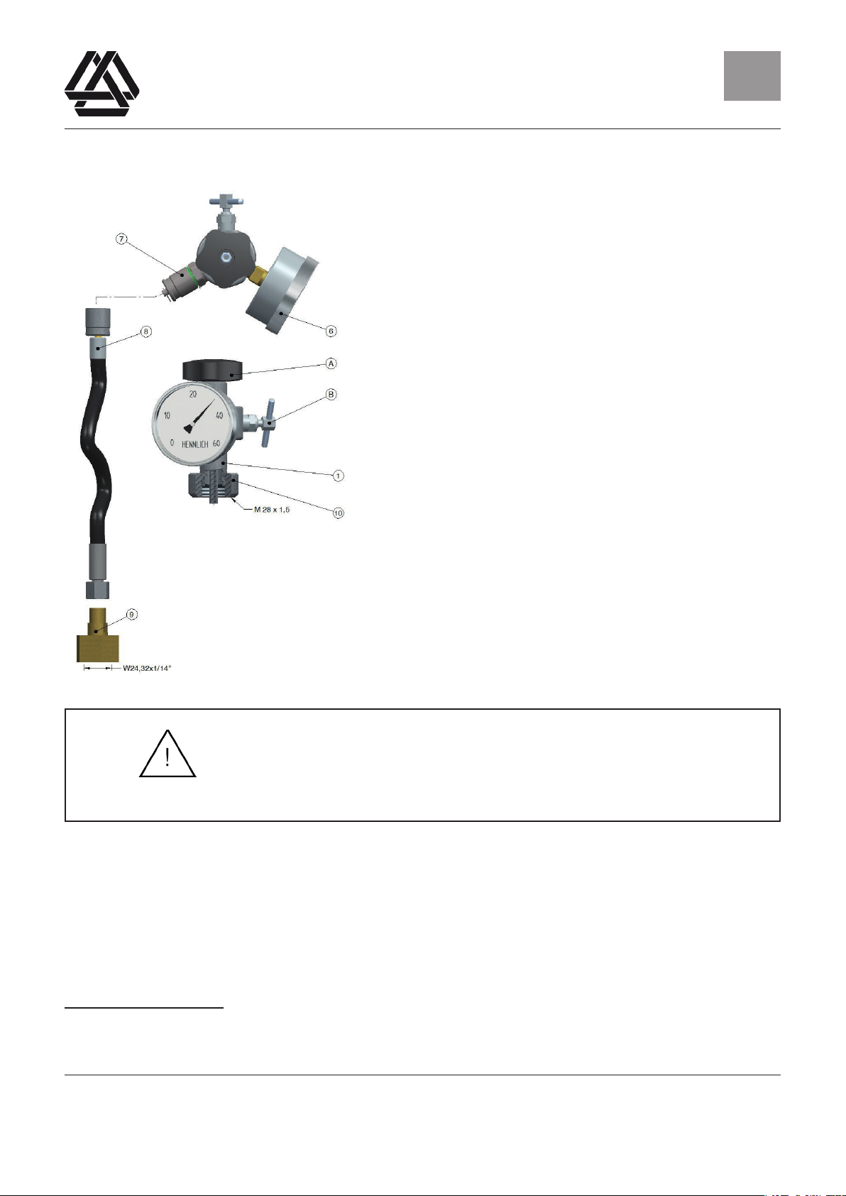
5.1 Prüfen des Vorfülldrucks
Die nachfolgende Anleitung gilt nur für Membran-
speicher, die mit einem Füllventil mit Ventilschraube
versehen sind.
Der Vorfülldruck P0 muss P1 (= minimaler Betriebs-
druck) x 0,8 sein.
a. Manometer mit einem, zu dem gewünschten
Vorfülldruck passenden Messbereich mit der
dazugehörigen Rautendichtung in die HFP ein
schrauben. Dabei sicherstellen, dass nur
Manometer mit gültiger Kalibrierung verwendet
werden!
b. Sicherstellen, dass das Ablassventil (B) an der
HFP geschlossen ist
c. Schutzkappe vom Gasventilkörper des
Membranspeichers abschrauben, um an die
Ventilschraube zu gelangen. Ventilschraube mit
einem Inbusschlüssel 6 mm lösen, aber nicht
herausschrauben.
Achtung!
Der Behälter kann unter hohem Druck stehen!!
Die Ventilschraube darf mit dem Inbusschlüssel nur gelöst, in
keinem Fall herausgeschraubt werden!!!
d. Die HFP so auf den Membranspeicher aufsetzten, daß das Manometer gut ablesbar
ist und der integrierte Innensechskantschlüssel in den Innensechskant der
Ventilschraube greift. Dann die Rändelmutter (10) handfest anziehen.
e. Die Ventilschraube des Membranspeichers durch Drehen des Handrades (A) gegen den
Uhrzeigersinn langsam öffnen, bis das Manometer den Fülldruck anzeigt.
Mögliche Anzeigen:
Nach dem Öffnen der Ventilschraube am Membranspeicher können drei unterschiedliche Fälle
beobachtet werden:

Seite 7 von 19
2_HMS_Betriebsanleitung_062017-de-eng
Stand: 11. September 2017
Bedienungs- und Wartungsanleitung Membranspeicher HMS
Instruction and Maintenance Manual Diaphragm Accumulator HMS DE
Vorfülldruck P0ist nicht vorhanden, oder zu gering
Vorfülldruck P0ist zu hoch
Vorfülldruck P0ist korrekt
5.1.1. Vorfülldruck nicht vorhanden oder zu gering
→ Befüllen des Membranspeichers mit Stickstoff
a. Die Ventilschraube des Hydrospeichers durch Drehen des Handrades (A) im Uhrzeiger
sinn wieder schließen.
b. Schutzkappe (7) der Füllschlauchanschlusskupplung entfernen.
c. Die Anschlusskupplung (8) des Füllschlauches mit der Füllschlauchanschlusskupplung
der HFP verbinden. Rändelmutter der Anschlusskupplung handfest anziehen.
d. Anschlusskupplung (9) des Füllschlauches mit dem Druckminderventil der Stick- stoffa
sche verbinden.
e. Das Ventil der Stickstoffasche langsam öffnen.
f. Die Ventilschraube des Membranspeichers durch Drehen des Handrades (A) gegen den
Uhrzeigersinn langsam öffnen, bis der gewünschte Vorfülldruck erreicht ist.
g. Wenn der gewünschte Vorfülldruck erreicht ist, wird das Ventil der Stickstoffa- sche
geschlossen.
h. Da sich der Membranspeicher beim Befüllen erwärmt, kann der tatsächliche Vor-
fülldruck erst sicher nach dem Temperaturausgleich zwischen Speicher und
Umgebungsluft ermittelt werden. Dies kann einige Minuten, bis zu einer Stunde dauern.
i. Der Vorgang (Punkt e). – g).) muss entsprechend wiederholt werden, bis der
gewünschte Vorfülldruck endgültig erreicht ist.
j. Wenn der gewünschte Vorfülldruck endgültig erreicht ist, die Ventilschraube des
Membranspeichers durch Drehen des Handrades (A) im Uhrzeigersinn schließen, dabei
Ventilschraube nur handfest anziehen!
k. Das Ablassventil (B) langsam öffnen, um die HFP und den Füllschlauch vom Stick-
stoffdruck zu entlasten.
l. Die Anschlusskupplung (8) des Füllschlauches von der Füllschlauchanschlusskupplung
der HFP vorsichtig entfernen.
m. Schutzkappe (7) wieder auf die Füllschlauchanschlusskupplung schrauben.

Seite 8 von 19
2_HMS_Betriebsanleitung_062017-de-eng
Stand: 11. September 2017
Bedienungs- und Wartungsanleitung Membranspeicher HMS
Instruction and Maintenance Manual Diaphragm Accumulator HMS DE
n. Die HFP vom Membranspeicher trennen und die Ventilschraube mit einem
Inbusschlüssel 6 mm mit 20+5 Nm anziehen.
Wenn die HFP vom Membranspeicher entfernt ist, die Dichtheit der Ventilschraube mit Leck-
Such-Spray überprüfen.
Wenn die Ventilschraube dicht ist, die Schutzkappen wieder auf das Gasventil aufschrauben.
5.1.2 Vorfülldruck zu hoch
Senken des Vorfülldrucks
a. Das Ablassventil (B) langsam öffnen und solange Stickstoff entweichen lassen, bis der
gewünschte Vorfülldruck angezeigt wird. (Temperaturausgleich beachten!)
b. Wenn der gewünschte Vorfülldruck erreicht ist, das Ablassventil (B) schließen.
c. Die Ventilschraube des Membranspeichers durch Drehen des Handrades (A) im
Uhrzeigersinn schließen, dabei Ventilschraube nur handfest anziehen!
d. Das Ablassventil (B) langsam öffnen, um die HFP vom Stickstoffdruck zu entlasten.
e. Die HFP vom Membranspeicher trennen und die Ventilschraube mit einem
Inbusschlüssel 6 mm mit 20+5 Nm anziehen.
Wenn die HFP vom Membranspeicher entfernt ist, die Dichtheit der Ventilschraube mit Leck-
Such-Spray überprüfen. Wenn die Ventilschraube dicht ist, die Schutzkappen wieder auf das
Gasventil auf- schrauben.
5.1.3 Vorfülldruck ist korrekt
a. Die Ventilschraube des Membranspeichers durch Drehen des Handrades (A) im
Uhrzeigersinn schließen, dabei Ventilschraube nur handfest anziehen!
b. Das Ablassventil (B) langsam öffnen, um die HFP vom Stickstoffdruck zu entlasten.
c. Die HFP vom Membranspeicher trennen und die Ventilschraube mit dem beigelegten
Inbusschlüssel 6 mm mit 20+5 Nm anziehen.
Wenn die HFP vom Membranspeicher entfernt ist, die Dichtheit der Ventilschraube mit Leck-
Such-Spray überprüfen. Wenn die Ventilschraube dicht ist, ist nach dem Abtrocknen des
Leck-Such-Sprays eine Markierung mit Sicherungslack anzubringen. Nach dem Trocknen des
Sicherungslackes, die Schutzkappen wieder auf das Gasventil aufschrauben.

Seite 9 von 19
2_HMS_Betriebsanleitung_062017-de-eng
Stand: 11. September 2017
Bedienungs- und Wartungsanleitung Membranspeicher HMS
Instruction and Maintenance Manual Diaphragm Accumulator HMS DE
5.2 Maximal zulässiger Betriebsdruck (PS)
Der maximal zulässige Betriebsüberdruck (PS) ist auf dem Speicherkörper vermerkt. Prüfen
sie, ob der maximal zulässige Betriebsüberdruck des Membranspeichers kleiner oder größer,
als der des hydraulischen Systems ist. Ist dies nicht der Fall, darf der Membranspeicher nicht in
Betrieb genommen werden. Kontaktieren sie in diesem Fall die HENNLICH – HCT GmbH.
5.3 Zulässiges Druckverhältnis
Das maximal zulässige Druckverhältnis (Pmax/P0) zwischen dem maximalen hydraulischen
Betriebsdruck (Pmax) und dem Vorfülldruck (P0) ist aus dem Datenblatt Membranspeicher
HMS ersichtlich.
Stellen Sie sicher, dass das tatsächliche Druckverhältnis kleiner ist, als das maximal zulässige
Druckverhältnis.
5.4 Zulässiger Temperaturbereich (TS)
Der zulässige Temperaturbereich (TS) ist auf dem Speicherkörper eingestempelt. Prüfen Sie,
ob diese zulässige Temperaturspanne die tatsächliche Betriebstemperatur ab- deckt. (Umge-
bungstemperatur und/ oder Temperatur der Hydrauliküssigkeit). Bei Abweichungen Kontaktie-
ren sie in diesem Fall die HENNLICH – HCT GmbH.
5.5 Geeignete, bzw. zugelassene Hydrauliküssigkeiten
Achten Sie beim Einsatz des Membranspeichers auf die Verträglichkeit des Membranelasto-
mers mit Ihrem Betriebsmedium. Im Zweifelsfall wenden Sie sich bitte an die HENNLICH –
HCT GmbH. Benutzen Sie nur Betriebsmedien der Fluidgruppe 2. Es ist nicht zulässig, den
Membranspeicher mit Betriebsmedien zu betreiben, für die er nicht bestimmt oder geeignet ist.
Betriebsmedien der Fluidgruppe 1 dürfen nicht in einem Membranspeicher der Fluidgruppe 2
angewendet werden.
Gruppe 1 (gefährliche Fluide) schließt explosionsgefährliche, hochentzündliche, leichtent-
zündliche, brandfördernde, sehr giftige und giftige Flüssigkeiten mit ein(EU- Verordnungs-Nr.
1272/2008).
Gruppe 2 (nicht gefährliche Flüssigkeiten) enthält alle anderen Flüssigkeiten.
5.6 Montage
Bei der Montage des Membranspeichers ist zu beachten:
- dass der Speicher so montiert ist, dass keine äußeren Kräfte auf ihn wirken.
- dass der Speicher ausreichend befestigt ist um unkontrollierten Bewegungen vorzu-
beugen.
- dass das angeschlossene Rohrsystem spannungsfrei verlegt ist.

Seite 10 von 19
2_HMS_Betriebsanleitung_062017-de-eng
Stand: 11. September 2017
Bedienungs- und Wartungsanleitung Membranspeicher HMS
Instruction and Maintenance Manual Diaphragm Accumulator HMS DE
Stellen Sie sicher, dass die Kennzeichnungen und Markierungen auf dem Speicher gut sicht-
bar und lesbar sind.
Lassen Sie über dem Gasventil des Membranspeichers mindestens 200 mm Platz für den Ein-
satz der Füll- und Prüfvorrichtung.
Beachten Sie die klimatischen Bedingungen am Aufstellungsort und schützen Sie den Mem-
branspeicher falls notwendig vor Wärmequellen, elektrischen und magnetischen Feldern, ge-
gen Blitzschlag, Feuchtigkeit und Korrosion und andere abträgliche Umgebungsbedingungen.
Für eine optimale Leistung platzieren Sie den Membranspeicher so nah wie möglich am Ver-
braucher. Bevorzugte Einbaulage ist vertikal (Gasventil oben) bis horizontal.
5.7 Wartung und regelmäßige Prüfungen
Überprüfen Sie den Vorfülldruck P0 im ersten Monat nach der Inbetriebnahme 1 mal wöchent-
lich.
Danach wiederholen Sie die Prüfung wieder nach einem Monat, danach halbjährlich oder gar
nur noch jährlich, abhängig davon, ob Sie einen Druckabfall im System feststellen.
Zudem sollten regelmäßig folgend Dinge überprüft werden:
- Lesbarkeit der Sicherheitshinweise
- Dichtheit der Anschlüsse
- Befestigung des Membranspeichers
- Mögliche Anzeichen von Abnutzung wie Korrosion oder Deformation
Unabhängig von diesen Prüfungen oder Kontrollen, die der Verlängerung der Lebensdauer der
Speicher dienen, unterliegen Druckgeräte gesetzlichen Prüfvorschriften.
Für die Einhaltung dieser Vorschriften ist der Betreiber des Druckgerätes verantwortlich.
5.8 Demontage und Recyling
Bevor Sie den Membranspeicher demontieren, stellen Sie sicher, dass das Hydrauliksystem
drucklos geschaltet ist und der Membranspeicher uidseitig entlastet ist.
Vor der Verschrottung des Speichers lassen Sie den Stickstoff ab und entfernen die Ventil-
schraube sowie nach Möglichkeit verbleibende Rückstände des Betriebsmediums.
6. Mitgeltende Unterlagen
Es ist die jeweils aktuelle Fassung der Bedienungsanleitung zur HENNLICH-Füll-und Prüfvor-
richtung zu beachten. Es gelten die Arbeitssicherheitsanweisungen gemäß Gefährdungsbeur-
teilung. Es gilt das jeweils aktuellste Datenblatt für HENNLICH – Membranspeicher.

Seite 11 von 19
2_HMS_Betriebsanleitung_062017-de-eng
Stand: 11. September 2017
Bedienungs- und Wartungsanleitung Membranspeicher HMS
Instruction and Maintenance Manual Diaphragm Accumulator HMS GB
Table of Contents
1. Scope and purpose
2. Abbreviations
3. Safety instructions
3.1. Alignment of the membrane reservoir during lling, checking or adjustment
of the nitrogen pre-lling
3.2. Labeling and marking of the HENNLICH diaphragm accumulator
4. Transport and storage
4.1. Transportation
4.2. Storage
5. Commissioning and maintenance
5.1. Checking the pre-lling pressure
5.1.1. Prell pressure not available or too low
5.1.2. Prell pressure too high
5.1.3. Prell pressure is correct
5.2. Maximum permissible operating pressure (PS)
5.3. Permissible pressure ratio
5.4. Permissible temperature range (TS)
5.5. Suitable or approved hydraulic uids
5.6. Mounting
5.7. Maintenance and regular checks
5.8. Dismantling and recycling
6. Applicable documents
Seite 12 von 19
2_HMS_Betriebsanleitung_062017-de-eng
Stand: 11. September 2017
Bedienungs- und Wartungsanleitung Membranspeicher HMS
Instruction and Maintenance Manual Diaphragm Accumulator HMS GB
1. Scope and purpose
These operating and maintenance instructions apply to all HENNLICH diaphragm
accumulators. The HENNLICH diaphragm accumulators are designed, manufactured and
tested in accordance with the European Directive 2014/68/EU. Strict adherence to the
instructions given in this and all other applicable documents is important. The supplier
accepts no responsibility for direct or indirect property damage or personal injury or
consequential damage such as loss of business arising from failure to comply with the
following instructions.
2. Abbreviations
HFP: HENNLICH - Filling and testing device
HMS: HENNLICH – diaphragm accumulator
3. Safety instructions
The applicable regulations for the safe operation of hydro-accumulators require the observance
of some safety-relevant measures:
- use of appropriate safety devices against excess pressure
- use of suitable drainage devices
- use of suitable pressure indicators
- Correct connection of pressure indicators
- use of suitable shut-off devices
- And other
Only nitrogen of type S (99.8%), type R (99.99%), or type U (99.993%) is permitted to ll
hydro-accumulators.
For lling hydraulic accumulators, never use oxygen,
Or use compressed air !
There is a risk of explosion!
If the maximum permissible operating pressure of the nitrogen bottle is greater than the
maximum permissible operating pressure of the hydraulic accumulator to be lled, a pressure-
reducing valve must be inserted between the nitrogen bottle and HFP.
However, HENNLICH - HCT GmbH generally recommends the use of a pressure reducing
valve. The diaphragm accumulators are delivered as follows:
- ready for use, prelled with nitrogen (P0) according to customer specications.
- with a low transport charge (between 3 and 10 bar).
In this case, the accumulator must be prelled by the customer in accordance with the

Seite 13 von 19
2_HMS_Betriebsanleitung_062017-de-eng
Stand: 11. September 2017
Bedienungs- und Wartungsanleitung Membranspeicher HMS
Instruction and Maintenance Manual Diaphragm Accumulator HMS GB
operating conditions before commissioning. In any case, check the pre-lling pressure
before commissioning. Ensure that the operating pressure of your system never exceeds the
permissible operating pressure of the diaphragm accumulator.
3.1 Alignment of the membrane reservoir during lling, checking or adjustment of the
nitrogen pre-lling
When lling the membrane reservoir with nitrogen or when checking or adapting the nitrogen
pre-lling, care must be taken to ensure that the accumulator is oriented such that the valve
screw of the diaphragm reservoir is not oriented either on persons or on objects. Position
yourself so that you can not be injured in the event of a possible leak, or in the event of a break
in the lling and testing device. Always use a lling and testing device and observe the valid
instructions for use. HENNLICH - HCT supplies this lling and testing device as an accessory.
3.2 Labeling and marking of the HENNLICH diaphragm accumulator
It is strictly forbidden to alter or even remove markings or data on the diaphragm accumulator
without the prior written consent of HENNLICH - HCT.
The membrane reservoir has the following markings on the storage body:
- Name of the producer
- manufacturer's reference number
- Nominal volume V of the diaphragm accumulator in liters
- operating temperature range TS in ° C
- Maximum operating pressure PS in bar
- Test pressure PT in bar
- Date of manufacture and testing
- Serial number of the diaphragm accumulator tank
For volumes larger than 1 liter, the CE logo with the identication number of the notied body is
stamped.
If the diaphragm accumulator has a nitrogen lling, the pre-ination pressure is indicated on the
sticker "Pre-ination pressure P0 = xx bar".
4. Transport and storage
The original packaging is suitable both for the safe transport and for the storage of the
diaphragm accumulator, as long as special packaging (eg sea transport) is not required.
4.1 Transportation
The diaphragm storage tank must be protected against pressure, impact and fall. The gas valve
must always be protected against damage.
Seite 14 von 19
2_HMS_Betriebsanleitung_062017-de-eng
Stand: 11. September 2017
Bedienungs- und Wartungsanleitung Membranspeicher HMS
Instruction and Maintenance Manual Diaphragm Accumulator HMS GB
4.2 Storage
Store in a cool, dry place. They must not be exposed to extreme heat or open re.
The storage of a diaphragm accumulator with a specic nitrogen pre-lling P0 over a
longer period is not recommended. Depending on the pre-lling pressure and the storage
temperature, the membrane can be damaged.
5. Commissioning and maintenance
The commissioning and maintenance of hydraulic accumulators and equipment may only be
carried out by qualied personnel.
Before commissioning, a visual check for external damage must be carried out. Before carrying
out any work on the hydraulic system, make sure that the system is pressureless. Installation
errors can lead to serious accidents. It is strictly forbidden:
- to weld, braze, drill or other mechanical work on the hydraulic accumulator, which may alter
the properties of the hydro-accumulator.
- modify the hydro accumulator or its components without written approval by HENNLICH -
HCT GmbH; Hydro accumulators are pressure vessels and there may be the risk of bursting or
exploding.
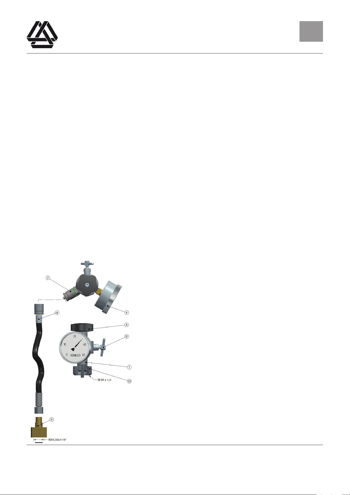
5.1 Checking the pre-lling pressure
The following instructions are only valid for diaphragm
accumulators equipped with a lling valve with Valve
screw.
a. The pre-lling pressure P0 must be P1
(= minimum operating pressure) x 0.8.
b. Screw the pressure gauge into the HFP with a
matching measuring range with the appropriate
roughness seal. Ensure that only pressure
gauges with valid calibration are used!
c. Make sure the drain valve (B) on the HFP is
closed unscrew the protective cap from
the gas valve body of the diaphragm
reservoir to connect to the screw.
Unscrew the valve screw with an allen
key 6 mm but do not unscrew it.

Seite 15 von 19
2_HMS_Betriebsanleitung_062017-de-eng
Stand: 11. September 2017
Bedienungs- und Wartungsanleitung Membranspeicher HMS
Instruction and Maintenance Manual Diaphragm Accumulator HMS GB
Caution!
The container can be under high pressure!!
The valve screw may only be loosened with the allen wrench,
in
no case screwed out !!!
d. Place the HFP on the diaphragm reservoir so that the manometer is easy to read and
the integrated hexagon socket wrench engages the hexagon socket of the valve screw.
Then tighten the knurled nut (10).
e. Slowly open the diaphragm valve by rotating the handwheel (A) counter - clockwise until
the gauge shows the lling pressure.
Possible ads:
Three different cases can be observed after opening the valve screw on the diaphragm
reservoir:
prell pressure Po is not available,
or too small prell pressure Po
Po it is too high
Po prell pressure is correct
5.1.1 Prell pressure is not available or too low
Filling the diaphragm accumulator with nitrogen
a. Close the valve screw of the hydraulic reservoir by turning the handwheel (A) clockwise.
b. Remove the cap (7) of the lling hose connection.
c. Connect the connection coupling (8) of the lling hose to the lling hose connection
coupling of the HFP. Tighten the knurled nut of the connection coupling by hand.
d. Connect the connection coupling (9) of the lling hose to the pressure reducing valve of
the nitrogen bottle.
e. Slowly open the nitrogen bottle valve.
f. Slowly open the valve screw of the diaphragm reservoir by turning the handwheel (A)
counter - clockwise until the desired pre - ination pressure Po is reached.

Seite 16 von 19
2_HMS_Betriebsanleitung_062017-de-eng
Stand: 11. September 2017
Bedienungs- und Wartungsanleitung Membranspeicher HMS
Instruction and Maintenance Manual Diaphragm Accumulator HMS GB
g. If the desired prell pressure Po is realized the valve of the nitrogen bottle is closed.
h. As the diaphragm accumulator heats up during lling, the actual pre-lling pressure can
be reached. Can only be ascertained reliably after the temperature compensation
between storage and ambient air. This may take several minutes, up to an hour.
i. The procedure (point e). - g).) Must be repeated accordingly until the desired pre-lling
pressure is nally achieved.
j. When the desired pre-ll pressure is nally reached, close the valve screw of the
diaphragm reservoir by turning the hand wheel (A) clockwise, while tightening the valve
screw only by hand!
k. Slowly open the drain valve (B) to relieve the HFP and the lling hose from the nitrogen
pressure.
l. Carefully remove the coupling (8) of the lling hose from the lling hose connection
coupling of the HFP.
m. Screw the protective cap (7) back onto the lling hose connection coupling.
n. Disconnect the HFP from the diaphragm accumulator and tighten the valve screw with a
6 mm Allen key with 20 + 5 Nm.
If the HFP is removed from the diaphragm reservoir, check the tightness of the valve screw with
leak detection spray. When the valve screw is tight, screw the protective caps back onto the gas
valve.
5.1.2 Prell pressure too high
Reduce the pre-lling pressure Po
a. Slowly open the drain valve (B) and allow nitrogen to escape until the desired priming
pressure is shown. (Observe temperature compensation!)
b. If the desired pre-ll pressure Po is realized, close the drain valve (B).
c. Close the valve screw of the diaphragm reservoir by turning the hand wheel (A)
clockwise, while tightening the valve screw only by hand!
d. Slowly open the drain valve (B) to relieve the HFP of the nitrogen pressure.
e. Separate the HFP from the diaphragm accumulator and tighten the valve screw with a
6 mm Allen key with 20 + 5 Nm.

Seite 17 von 19
2_HMS_Betriebsanleitung_062017-de-eng
Stand: 11. September 2017
Bedienungs- und Wartungsanleitung Membranspeicher HMS
Instruction and Maintenance Manual Diaphragm Accumulator HMS GB
If the HFP is removed from the diaphragm reservoir, check the tightness of the valve screw with
leak detection spray.
5.1.3 Prell pressure is correct
a. Close the valve screw of the diaphragm reservoir by turning the hand wheel (A)
clockwise, while tightening the valve screw only by hand!
b. Slowly open the drain valve (B) to relieve the HFP of the nitrogen pressure.
c. Disconnect the HFP from the diaphragm accumulator and tighten the valve screw to
20 + 5 Nm using the Allen key supplied.
If the HFP is removed from the diaphragm accumulator, check the tightness of the valve screw
with leak detection spray. If the valve screw is tight, a marking with a safety lacquer must be
applied after the leak detection spray has dried. After drying the protective varnish, screw the
protective caps back onto the gas valve.
5.2 Maximum permissible operating pressure (PS)
The maximum permissible operating pressure (PS) is indicated on the storage tank. Check
whether the maximum permissible operating pressure of the diaphragm reservoir is smaller or
larger than that of the hydraulic system. If this is not the case, the diaphragm storage tank must
not be put into operation. In this case, please contact HENNLICH - HCT GmbH.
5.3 Permissible pressure ratio
The maximum permissible pressure ratio (Pmax / P0) between the maximum hydraulic
operating pressure (Pmax) and the pre-lling pressure (P0) can be seen in the data sheet
Membrane reservoir HMS.
Ensure that the actual pressure ratio is less than the maximum permissible pressure ratio.
5.4 Permissible temperature range (TS)
The permissible temperature range (TS) is stamped on the storage body. Check whether this
allowable temperature range covers the actual operating temperature. (Ambient temperature
and / or temperature of the hydraulic uid) In the event of deviations, please contact
HENNLICH - HCT GmbH.
5.5 Suitable or approved hydraulic uids
When using the diaphragm accumulator, ensure the compatibility of the membrane nebulizer

Seite 18 von 19
2_HMS_Betriebsanleitung_062017-de-eng
Stand: 11. September 2017
Bedienungs- und Wartungsanleitung Membranspeicher HMS
Instruction and Maintenance Manual Diaphragm Accumulator HMS GB
with your operating medium. If in doubt, please contact HENNLICH - HCT GmbH. Only use
operating media of uid group 2.It is not permissible to operate the diaphragm storage tank
with operating media for which it is not intended or suitable.
Operating media of the uid group 1 may not be used in a diaphragm reservoir of the
uid group 2.
Group 1 (hazardous uids) includes explosive, highly ammable, easily ammable, re-
promoting, very toxic and toxic liquids (see EU- provision -No. 1272/2008).
Group 2 (non-hazardous liquids) contains all other liquids.
5.6 Mounting
Observe the following when installing the diaphragm:
- the accumulator is mounted in such a way that no external forces act on it.
- that the accumulator is sufciently fastened to prevent uncontrolled movements.
- that the connected pipe system is installed without stress.
Make sure that the markings and markings on the memory are well visible and legible.
Leave at least 200 mm above the gas valve of the diaphragm storage for the use of the lling
and testing device.
Observe the climatic conditions at the installation site and, if necessary, protect the diaphragm
storage tank from heat sources, electrical and magnetic elds, lightning strikes, moisture
and corrosion and other adverse environmental conditions. For optimal performance, place
the diaphragm accumulator as close to the load as possible. Preferred installation position is
vertical (gas valve top) to horizontal.
5.7 Maintenance and regular checks
Check the pre-ll pressure P0 in the rst month after commissioning 1 time a week.
Then repeat the check after one month, then half-yearly or even only annually, depending on
whether you notice a pressure drop in the system.
In addition, things should be checked regularly:
- Readability of the safety instructions
- Sealing of connections
- Fastening the diaphragm
- Possible signs of wear such as corrosion or deformation
Irrespective of these tests or controls, which serve to extend the life of the accumulators,
pressure equipment is subject to legal test regulations.
The operator of the pressure device is responsible for compliance with these regulations.

Seite 19 von 19
2_HMS_Betriebsanleitung_062017-de-eng
Stand: 11. September 2017
Bedienungs- und Wartungsanleitung Membranspeicher HMS
Instruction and Maintenance Manual Diaphragm Accumulator HMS GB
5.8 Dismantling and recycling
Before disassembling the diaphragm accumulator, make sure that the hydraulic system is
depressurized and that the diaphragm reservoir is relieved on the uid side. Before scraping
the reservoir, drain the nitrogen and remove the valve plug and, if possible, remaining residues
of the operating medium.
6. Applicable documents
The current version of the operating instructions for the HENNLICH lling and testing device
must be observed. The work safety instructions according to the hazard assessment apply. The
latest data sheet for HENNLICH - diaphragm accumulator is valid.
Table of contents
Languages:


