Alpha Lomain User manual

Alpha Lomain Ni-Cd Pocket Plate Battery
Technical Manual
Effective: July 2009
Alpha Technologies

Power
Alpha Technologies
®

3
745-680-B10-001 Rev. A
member of The Group
TM
Alpha Lomain Ni-Cd Pocket Plate Battery
Technical Manual
745-680-B10-001, Rev. A
Effective Date: July, 2009
Copyright© 2009
Alpha Technologies, Inc.
Contacting Alpha Technologies: www.alpha.com
or
For general product information and customer service (7 AM to 5 PM, Pacic Time), call
1-800-863-3930,
For complete technical support, call
1-800-863-3364
7 AM to 5 PM, Pacic Time or 24/7 emergency support
Alpha shall not be held liable for any damage or injury involving its enclosures, power supplies, generators,
batteries, or other hardware if used or operated in any manner or subject to any condition not consistent with
its intended purpose, or is installed or operated in an unapproved manner, or improperly maintained.
Photographs contained in this manual are for illustrative purposes only. These photographs may not match
your installation.
NOTE:
Operator is cautioned to review the drawings and illustrations contained in this manual before proceeding. If
there are questions regarding the safe operation of this powering system, please contact Alpha Technologies
or your nearest Alpha representative.
NOTE:
NOTE:

745-680-B10-001 Rev. A
4
Table of Contents
Safety Notes.......................................................................................................................... 6
Battery Safety Precautions.................................................................................................... 7
1.0 Introduction................................................................................................................. 9
1.1 Alpha Lomain Theory of Operation ......................................................................11
1.2 Safety terminal ................................................................................................... 14
1.3 Electrode Frame ................................................................................................. 14
1.4 Positive and negative electrode plate ................................................................ 14
1.5 Electrolyte .......................................................................................................... 15
2.0 Battery range and applications ..................................................................................... 16
3.0 Electrochemistry of Ni-Cd batteries .............................................................................. 16
4.0 Operating Features ....................................................................................................... 17
4.1 Capacity.............................................................................................................. 17
4.2 Cell voltage ........................................................................................................ 17
4.3 Internal resistance ............................................................................................. 17
4.4 Impact of temperature on cell performance and available capacity .................. 18
4.5 Impact of temperature on lifetime ...................................................................... 19
4.6 Short-circuit values ............................................................................................ 19
4.7 Open circuit loss ................................................................................................. 19
4.8 Cycling ............................................................................................................... 20
4.9 Topping up interval ............................................................................................. 21
5.0 Sizing the batteries for standby applications ................................................................. 22
5.1 Voltage window................................................................................................... 22
5.2 Load prole......................................................................................................... 22
5.3 Ambient temperature .......................................................................................... 22
5.4 Recharge time and state of charge..................................................................... 22
5.5 Aging................................................................................................................... 22
5.6 Floating effect -Voltage depression .................................................................... 23

5
745-680-B10-001 Rev. A
Table of Contents
6.0 Charging ....................................................................................................................... 24
6.1 Constant voltage charge..................................................................................... 24
6.2 Charge acceptance............................................................................................. 25
6.3 Charge efciency ............................................................................................... 26
6.4 Temperature inuence ........................................................................................ 26
7.0 Commissioning ............................................................................................................. 27
7.1 Commissioning with constant current ................................................................ 27
7.2 Commissioning with constant voltage ................................................................ 27
8.0 Charging in operation ................................................................................................... 28
8.1. Two level charge................................................................................................ 28
8.2. Single level charge ........................................................................................... 28
9.0 Periodic Maintenance.................................................................................................... 28
Figures and Tables
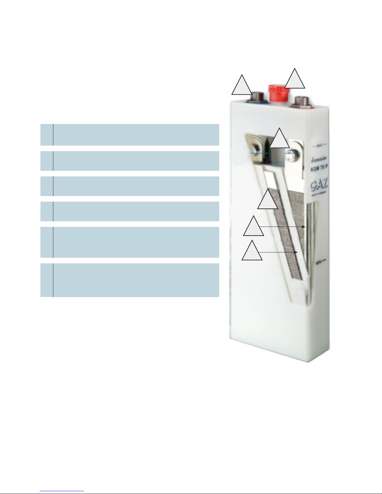
Fig. 1, Design of an Alpha Lomain Ni-Cd pocket plate cell ................................................................. 10
Fig. 2, Detail of plate design .................................................................................................................11
Fig. 3, Battery Vent .............................................................................................................................. 12
Fig. 4, Exploded view, Battery vent ..................................................................................................... 12
Fig. 5, Smaller Capacity Batteries ....................................................................................................... 13
Fig. 6, Larger Capacity Batteries ......................................................................................................... 13
Fig. 7, Terminal cross-section.............................................................................................................. 14
Fig. 8, Electrode Strip .......................................................................................................................... 14
Fig. 9, Strips connected....................................................................................................................... 15
Fig. 10, NiCd vs. Lead-Acid performance as a function of temperature.............................................. 18
Fig. 11, Discharge curve of 45A x 4 KGL225P post-2224h Float Charge @ 50°C.............................. 18
Fig. 12, Battery life at higher temperatures as percentage of +25°C lifetime ...................................... 19
Fig. 13, Cycle life vs. depth of discharge as a percentage of rated capacity (20°C) ........................... 20
Fig. 14, Available 5-hour-capacity of 5 x KGM 140P after 15 hours charging at 1.43 V/pc at 30°C.... 25
Fig. 15, Total Discharge time 4:43h = 94% of nominal capacity.......................................................... 25
Fig. 16, Available 5-hour-capacity of 5 x KGL 665P after 15 hours charging at 1.43 V/pc at 30°C ..... 25
Fig. 17, Total Discharge time 4:15h = 85% of nominal capacity.......................................................... 25

745-680-B10-001 Rev. A
6
Safety Notes
Review the drawings and illustrations contained in this manual before proceeding. If there are any questions
regarding the safe installation or operation of this product, contact Alpha Technologies or the nearest Alpha
representative. Save this document for future reference.
To reduce the risk of injury or death, and to ensure the continued safe operation of this product, the following
symbols have been placed throughout this manual. Where these symbols appear, use extra care and
attention.
The use of ATTENTION indicates specic regulatory/code requirements that may affect the placement of
equipment and /or installation procedures.
ATTENTION:
A NOTE provide additional information to help complete a specic task or procedure.
NOTE:
The use of CAUTION indicates safety information intended to PREVENT DAMAGE to material
or equipment.
CAUTION!
WARNING presents safety information to PREVENT INJURY OR DEATH to the
technician or user.
WARNING!

7
745-680-B10-001 Rev. A
Battery Safety Precautions
Once the battery has been lled with the correct electrolyte at the factory there is no need to
periodically check the electrolyte density
NOTE:
Check regularly (appr. every year) that all connectors, nuts and screws are tightly •
fastened. All metal parts of the battery should be corrosion-protected by coating with
a thin layer of anti-corrosion grease. Do not coat any plastic part of the battery, for
example, the cell cases.
Check the charging voltage. If a battery is parallel connected it is important that•
the recommended charging voltage remains unchanged. The charging current in
the strings should also be checked to ensure it is equal. These checks has to be
carried out once a year. High water consumption of the battery is usually caused by
improper voltage setting of the charger.
The battery pack, which provides backup power, contains dangerous voltages. Only•
qualied personnel should inspect, service or replace batteries.
If batteries are being stored prior to installation, charge at least once every six (6) •
months to ensure optimum performance and maximum battery service life.
Reduce the chance of spark and wear on the connectors; always switch the•
inverter’s battery circuit breaker off before connecting or disconnecting the battery
pack
Always use proper lifting techniques whenever handling batteries.•
In the event of a short-circuit, batteries present a risk of electrical shock and burns•
from high current. Observe proper safety precautions. Always carry a supply of
water, such as a water jug, to wash the eyes or skin in the event of exposure to
battery electrolyte.
The battery must be kept clean using only water. Do not use a wire brush or solvents•
of any kind.
Service personnel must always wear protective clothing (e.g., rubber gloves, safety goggles
with side guards, or a face shield) when working with electrolyte and on cells / batteries.
WARNING!

745-680-B10-001 Rev. A
8
Battery Safety Precautions, continued
Check the electrolyte temperature from time to time. The temperature of the•
electrolyte should never exceed 45 °C as higher temperatures have a detrimental
effect on the function and duration of the cells. In the course of charging an
electrolyte temperature of ≤ 35 °C should be aimed for. On exceeding 45 °C the
charging should be temporarily interrupted until the electrolyte temperature falls
down to 35 °C. The temperature measurements are to be made on one of the cells
in the middle of the battery. Low ambient or electrolyte temperatures down to –25
°C do not have any detrimental effect on the battery they just cause a temporary
reduction in capacity.
NiCd batteries must not be stored in the same room as lead acid batteries. Also, the•
charging gases from lead acid batteries must be kept away from Ni-Cd batteries by
suitable precautions such as ventilation or hermetic isolation of the rooms. Tools for
lead acid batteries must not be used for NiCd batteries
Do not place electrically conductive objects (e.g., tools) on the battery as this is a •
short circuit and re hazard.
Do not wear rings, metal bracelets, watches, or jewelry when working with the•
batteries and battery systems.
Provide sufcient ventilation (e.g., open the doors of the battery cabinet) during •
charging so any accumulated gases can escape. The charging gases from batteries
are explosive.
Do not allow open re or ember in the vicinity of the battery.•
Caustic potash solution is used as electrolyte, and is a highly corrosive liquid which•
can cause severe damage to health if it comes into contact with the eyes or the
skin (risk of blinding). If even small quantities are swallowed there is a possibility of
internal injuries.
Contact with the eyes: Flush out immediately with copious amounts of water for 10•
to 15 minutes, and seek immediate medical attention.
Contact with the skin: Remove splashed clothing immediately and wash the affected•
skin areas with copious amounts of water, and seek immediate medical attention.
Swallowing: Rinse out the mouth immediately with large amounts of water and•
keep drinking large amounts of water. Do not induce vomiting, and seek immediate
medical attention.

9
745-680-B10-001 Rev. A
1.0 Introduction
The Alpha Lomain Ni-Cd pocket plate battery is one of the most reliable batteries available and is
well-suited for operation under extreme environmental conditions. Features of the Alpha Lomain
Ni-Cd pocket plate battery include the following:
• Very good high power rating.
• Low internal resistance.
• Reduced loss of capacity at deep temperature.
• No ice formation at temperatures below 0 °C.
• Long lifetime at high temperatures.
• Resistant to the affects of repeated deep discharges.
• Long shelf life.
• No electrolyte stratication.
• Robust construction makes the battery well-suited for use in extreme conditions.

745-680-B10-001 Rev. A
10
Fig. 1, Design of a Alpha Lomain Ni-Cd pocket plate cell
1.0 Introduction, continued
1Low-pressure, ame-arresting vent; prevents
carbonate formation.
2Safety terminal; Redundant leak protection
minimizes carbonate formation.
3Electrode Edge; connected to pole bolt via
hardware for high mechanical stability
4Horizontal pockets; formed by perforated steel
strips containing the active material.
5
Electrode frame; Comprised of electrode edge
and side bars. Seals the plates and serves as a
current collector
6
Fiber mat separator; special separator
insulates the plates and improves the internal
recombination.
21
3
4
5
6

11
745-680-B10-001 Rev. A
1.0 Introduction, continued
1.1 Theory of Operation
A standard Ni-Cd ooded battery type needs to be topped up with distilled water after a
certain period of time depending on charging regime and operating temperature. The loss of
water during overcharge is caused by the following chemical reaction:
At the positive plate 4OH-→ 2H2O + O2 + 4e -Oxygen Evolution
At the negative plate 4H2O + 4e -→ 2H2 + 4OH-Hydrogen Evolution
In theory, the quantity of water used according to Faraday’s equation is that each ampere
hour of overcharge breaks down 0.336 cm3of water. While charging a Ni-Cd battery oxygen
evolution occurs just before the positive plate reaches its fully state of charge and reaches
its peak if it becomes fully charged. Since the negative plate provides a much better charge
acceptance than the positive plate hydrogen is not evolved until it has reached its
fully-charged state.
In order to reduce the water consumption Alpha Lomain-concept has been developed based
on four distinctive key features:
Plate design
Seperation system
Venting system
Cell design
Special plate design
Alpha Lomain batteries have been designed with an excess of negative material (cadmium)
to ensure that oxygen evolution occurs prior to hydrogen evolution to enhance the above
mentioned effect.
Oversized negative plate
Felt seperator
Fig. 2, Detail of plate design

745-680-B10-001 Rev. A
12
1.0 Introduction, continued
1.1 Theory of Operation, continued
Special seperation system
The oxygen created at the positive plate is absorbed by a special felt seperator and
prevented to escape from the distance between the plates. Displacement of electrolyte
by oxygen boubles occur within the seperator and reach the surface of the negative plate
causing the following reaction:
Chemically:
2Cd + O2+ 2H2O → 2Cd(OH)2
This reaction chemically discharges a certain amount of cadmium to cadmium
hydroxide. The current going through the battery recharges this material.
Electrochemically:
O2+ 2H2O+ 4e → 4OH
This reaction consumes the current directly; that is, hydrogen evolution at the
negative plate is prevented since the preferred reaction is oxygen recombination.
Special venting system
The battery cells are equipped with a low pressure ame arresting vent which operates as
a one way valve and allows to escape hydrogen and non-recombined oxygen and xes the
internal pressure at 0.2 bar.
Porous disc
Pressure rubber
Plastic particles
Sealing ring
Fig. 3, Battery Vent
Fig. 4, Exploded view, Battery vent

13
745-680-B10-001 Rev. A
1.0 Introduction, continued
1.1 Theory of Operation, continued
Single cell design
Due to the pressure inside of the battery cell, which is needed to reach a high recombination
level, a sturdy cell design is necessary to prevent leakage. The cells of the Lomain battery
are injection-molded from a single piece of plastic to prevent leakage of the cell casing and
the seams (welded or glued) of the cell cases and the lids are above the electrolyte level. The
single cell design completely eliminates the risk of faulty welded seams on the sides and on
the bottom of the cell cases. This design enhances system economy as it enables the service
personnel to replace only the defective cell(s).
3
Fig. 5, Smaller Capacity Batteries Fig. 6, Larger Capacity Batteries
1Sealed seams (glued or welded above Electrolyte level)
2One piece case
3Electrolyte level
2
11
2
3

745-680-B10-001 Rev. A
14
1.3 Electrode Frame
The electrode frame consists of a right and a left side bar as well as the electrode edge
which are connected by welding, giving shape to the electrode frame. The electrode frame
operates as a current collector and also seals the electrode plates. This procedure leads to
an electrode design with high mechanical robustness but also ensures a reliable service for
the complete lifetime of the battery.
1.4 Positive and negative electrode plate
The nickel-cadmium cell is composed of the positive plates containing nickel hydroxide and
the negative plates containing cadmium hydroxide.
Individual pockets are formed from a nickel plated and perforated steel tape (pocket tape)
and house strips of the active material.
1.0 Introduction, continued
1.2 Safety terminal
Tha Alpha Lomain battery features a specially developed terminal design with a redundant
leak protection to prevent electrolyte leakage. The battery terminals may be either male
of female threaded, depending upon the type and range of the battery. In either case, the
polarity of the terminals will be clearly indicated (color-coded).
Fig. 7, Terminal cross section
Fig. 8, Electrode Strip
1Pocket tape
2Active material
1
2

15
745-680-B10-001 Rev. A
The electrode strips are mechanically linked together to form the electrode plate and are
consecutively cut to the appropriate width based on the cell type and range. The plates then
are welded or mechanically linked to the plate frame (see Fig. 8) to form the electrodes, then
assembled to the plate block.
The extemely long useful lifetime and the very good cycle life features of the Ni-Cd pocket
plate batteries are a direct result of the special plate designs whose structural components
are made of steel.
This prevents the gradual deterioration by corrosion. Because the alkaline electrolyte does
not react with steel, the substructure of the battery remains intact for the total lifetime of the
battery. The integrity of the substructure is maintained by surrounding the electrochemical
active mass in perforated nickel-steel pockets, reducing the risk of shedding or penetration of
material as well as the risk of structural damage. Also, this design allows for the control of soft
short circuits.
1.5 Electrolyte
The electrolyte used in the Ni-Cd batteries is a solution of potassium hydroxide and lithium
hydroxide that is optimized to give the best combination of performance, energy efciency
and a wide temperature range of use.
It is an important property of the battery, and indeed all nickel-cadmium batteries, that the
electrolyte does not change during charge and discharge. It retains its ability to transfer ions
between the cell plates, irrespective of the charge level.
In most applications the electrolyte will retain its effectiveness for the life of the battery and
will never need replacing. However, under certain conditions, such as extended use in high
temperature situations, the electrolyte can become carbonated. If this occurs the battery
performance can be improved by replacing the electrolyte (see ·Maintenance and Handling
Instructions“).
1.0 Introduction, continued
1.4 Positive and negative electrode plate, continued
1Electrode Strips
2Mechanical Linkage
1
2
1
Fig. 9, Strips connected

745-680-B10-001 Rev. A
16
2.0 Battery range and applications
3.0 Electrochemistry of Ni-Cd batteries
Oxidation of cadmium at the negative electrode
Reduction of trivalent nickel ions to bivalent at the positive electrode
During charging the both reactions are reversed.
The complete reaction is: indicated below:
Negative electrode:
Positive electrode
Cell reaction
LOMAIN KGL...P
The Alpha Lomain cell type is used for low rates of discharge over
long periods where the current is relatively low in comparison with
the total stored energy. The discharges can generally be infrequent
and the recommend discharge time for the KGL...P range is 1 hour
to 100 hours.
LOMAIN KGM...P
The KGM...P type battery is designed for “mixed loads” that include a
mixture of high and low rates of discharge. It is used for frequent and
infrequent discharges and the recommended discharge time is 30 to
120 minutes.
Cd Cd2+ + 2e–
Ni3+ + e– Ni2+
Cd + 2 OH– Cd(OH)2+ 2e–
2NiOOH + 2 H2O+2e– Cd(OH)2+ 2e–
2NiOOH + Cd + 2 H2O 2Ni(OH)2 + Cd(OH)2

17
745-680-B10-001 Rev. A
4.0 Operating Features
4.1 Capacity
The capacity of Nickel-Cadmium batteries is rated in ampere-hours (Ah) and is the quantity of
electricity at +20 °C (± 5 °C) available for a 5 hour discharge after being fully charged for 15
hours at 0.2C5. These gures and procedures are based on the IEC 62259 standard.
According to IEC 62259, 0.2C5A is also expressed as 0.2 ItA. The reference test current It is
expressed as:
ItA= Cn Ah 1h
Cn is the rated capacity declared by the manufacturer in ampere-hours (Ah) n is the
time based in hours (h) for which the rated capacity is declared
4.2 Cell voltage
The cell voltage of a Ni-Cd cell is the result of the electrochemical potentials of the Nickel and
the Cadmium active materials in the Potassium hydroxide electrolyte. Therefore, the nominal
voltage for this electrochemical couple is 1.2 V. From the electrochemistry of the reaction
given above, the free voltage of 1.3 V is given for the Ni-Cd cell. This voltage is also observed
directly after charging of the cell.
4.3 Internal resistance
The internal resistance of a Ni-Cd cell is dependant upon several factors, e.g., battery
temperature, state of discharge (whether high or low), cell type and size. The internal
resistance also depends on the cell type and size as well; it increases for lower state of
charge. Apart from this the internal resistance of a fully discharged cell no carries weight.
Reducing the temperature also increases the internal resistance. Contact your local
representative for specic information regarding conditions that may affect the battery.

745-680-B10-001 Rev. A
18
4.0 Operating Features, continued
4.4 Impact of temperature on cell performance and available
capacity
When sizing and choosing a battery the variations in ambient temperature and their inuence
on the cell performance have to be taken into consideration. Low ambient temperature
conditions reduce the cell performance. However, operations with higher temperatures are
similar to those at normal temperatures. Lomain next generation batteries offer improved
values especially at high temperature applications. The effects of low-temperature operation
increase with higher rates of discharge.
The values, which have to be taken into account, can be found in the following graph.
Lomain next generation batteries passed a long term temperature test at constant +50°C
surrounding temperature followed by a discharge test out of the oat mode as indicated on
the chart below.
Fig. 10, NiCd vs. Lead-Acid performance as a function of temperature
Fig. 11, Discharge curve of 45A x 4 KGL225P post-2224h Float Charge @ +50°C

19
745-680-B10-001 Rev. A
4.0 Operating Features, continued
4.5 Impact of temperature on lifetime
Operating battery systems at higher temperatures reduces the service life. The Alpha Lomain
Ni-Cd battery is designed to be less susceptible to the affects of higher temperatures than
lead-acid batteries as shown by the following graph.
For standard Ni-Cd batteries the normal operating temperature is based at + 20 °C (± 5 °C)
and, therefore, special considerations have to be taken into account when specifying a Ni-Cd
battery for high temperature applications.
4.6 Short-circuit values
The short-circuit values of a Alpha Lomain Ni-Cd pocket plate battery are unique to each cell
range. Contact your dealer for specic information.
4.7 Open circuit loss
The state of charge of a cell on open circuit slowly decreases due to its self-discharge.
This decrease is quite rapid during the rst two weeks and then stabilizes at about 2% per
month at +20°C.
In general the self-discharge of a Ni-Cd battery is affected by various temperatures. The open
circuit loss is reduced at low temperatures; that is, the self-discharge is signicantly increased
at higher temperatures.
Fig. 12, Battery life at higher temperatures as percentage of +25°C lifetime

745-680-B10-001 Rev. A
20
4.0 Operating Features, continued
4.8 Cycling
The Alpha Lomain Ni-Cd battery is designed to perform a signicant number of charge-
discharge cycles in stationary standby operations.
The determining factor for the number of charge-discharge cycles the battery is able to
provide is the depth of discharge.
A battery that is less deeply discharged will provide more charge-discharge cycles until it
reaches the point at which it can no longer provide the minimum design limit.
Conversely, a battery that has been more deeply discharged will have a shorter charge-
discharge cycle life.
The graph below illustrates typical values for the effect of depth of discharge on the available
charge-discharge cycle life.
Fig. 13, Cycle life vs. depth of discharge as a percentage of rated capacity (20°C)
Table of contents
Other Alpha Batteries Pack manuals