Must LP2000 Series User manual
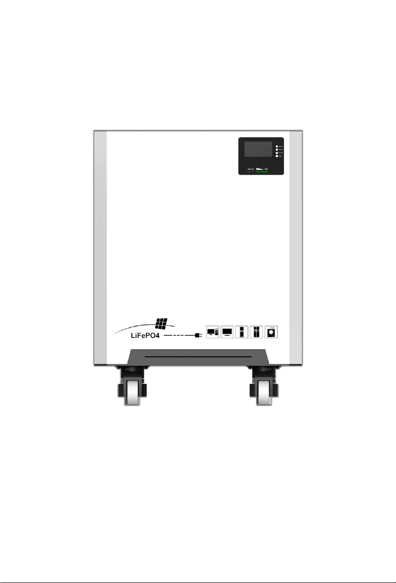
Rechargeable LiFePO4 Battery
LP2000 Series
User Manual

1. Safety Instructions...............................................................1
1.1 Before connecting...................................................................2
1.2 In Using....................................................................................2
2. Introduction........................................................................3
2.1 Product Features.....................................................................3
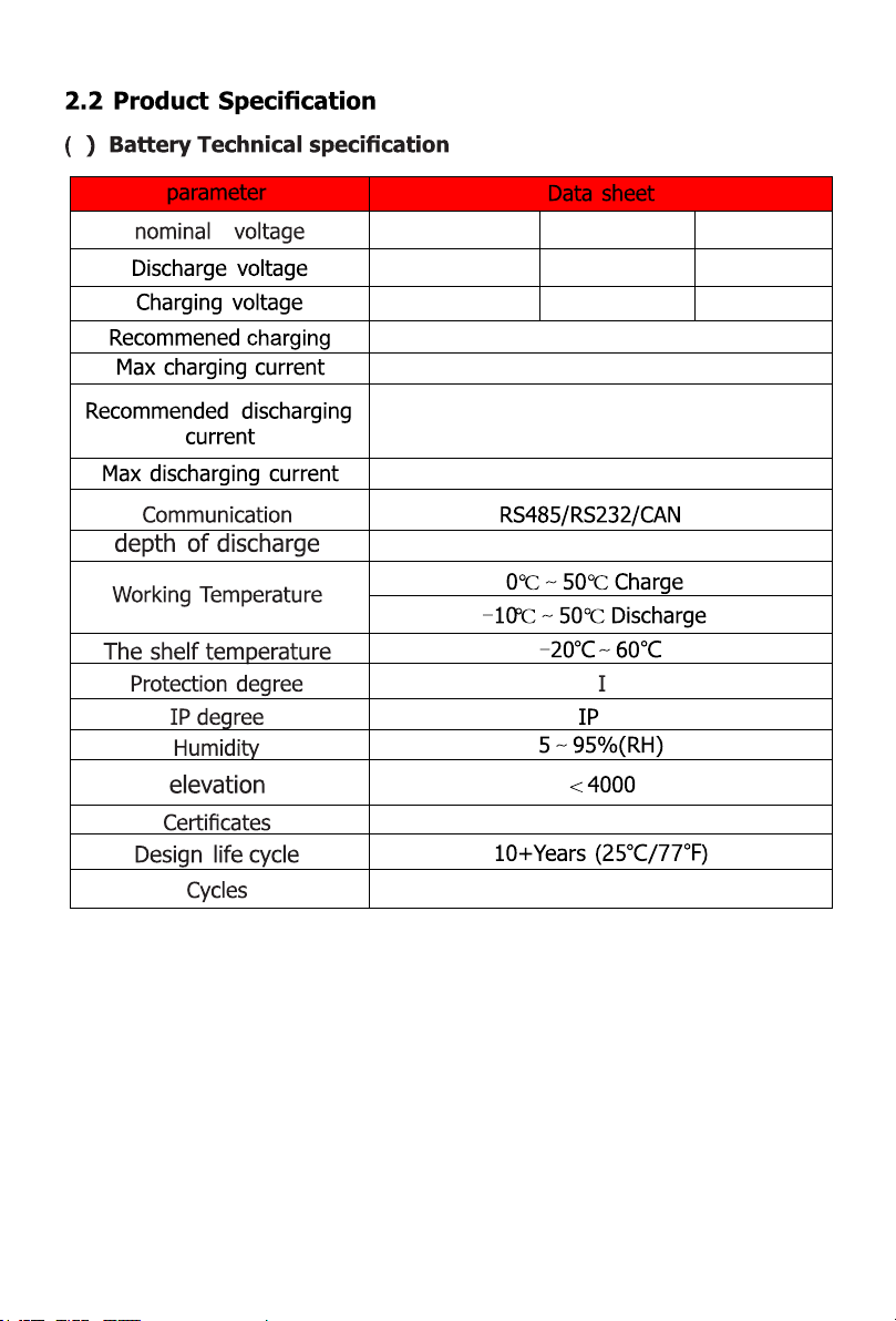
2.2 Product Specification...............................................................4
2.3 Equipment interface instruction.................................................5
2.4 Battery cables terminal...........................................................10
2.5 LED Status Showing...............................................................11
2.6 BMS basic function.................................................................11
3. Safe handling Guide of Lithium Battery..............................12
3.1 Schematic diagram of solution...............................................12
3.2 Danger Label........................................................................12
3.3 Tools...................................................................................12
3.4 Safety gear...........................................................................13
4. Installation and Operation.................................................13
4.1 Package Items......................................................................13
4.2 Installation Location..............................................................14
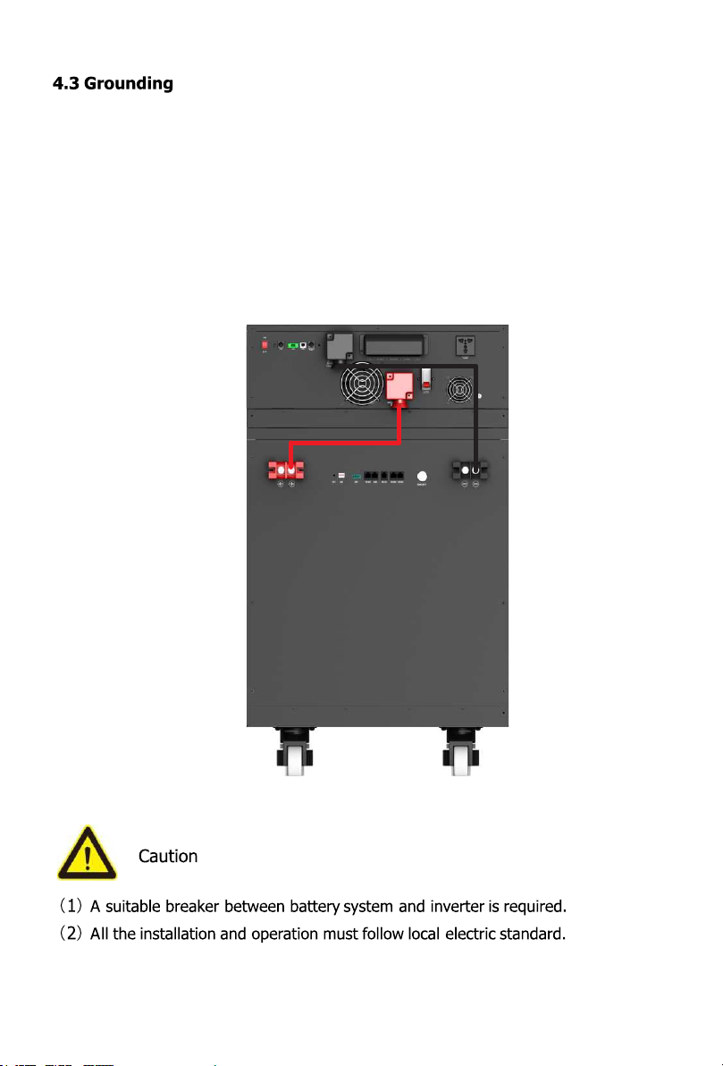
4.3 Grounding............................................................................15
4.4 Put into cabinet or racks...........................................................15
4.5 Power on..............................................................................16
4.6 Power off..............................................................................17
4.7 Multi-group mode..................................................................17
5. Trouble shooting................................................................18
6. Emergency Situations.........................................................20
7. Remarks.............................................................................21
please read this manual before installing the battery, and follow the instructions
carefully during the installation process. If you have any doubts, please contact
your sellerfor assistance immediately.

1) Before installing or using the battery, it is important and necessary to
read the user manual carefully. Failure to do so or to follow any
instructions or warnings in this document may result in electric shock,
serious injury or death, or may damage the battery, potentially rendering
it inoperable.
2) If the battery is stored for long time, it is required to charge them
every six months, and the SOC should be no less than 90%.
3) The battery needs to be charged within 12 hours, after full discharge.
4) Do not install the product in an outdoor environment, or an environment
beyond the operating temperature or humidity range listed in the manual.
5) Do not expose the cable to the outside.
6) Do not connect power terminal reversely.
7) All battery terminals must be disconnected for maintenance.
8) Please contact the supplier within 24 hours if there is something abnormal.
9) Do not use detergent to clean the battery.
10) Do not expose batteries to flammable or harsh chemicals or vapors.
11) Do not paint any part of the battery, including any internal or external
components.
12) Do not connect battery with PV solar wiring directly.
13) The warranty claims are excluded for direct or indirect damage due to
items above.
14) Any foreign object is prohibited to insert into any part of battery.
1
1. Safety Precautions

1.1 Before connecting
1) After unpacking, please check the product and packing list first, if the
product is damaged or missing parts, please contact your local dealer
seller contact.
2) Before installation, be sure to cut off the grid power and make sure the
battery is in the turned-off mode.
3) Wiring must be correct, do not mistake the positive and negative cables,
and ensure no short circuit with the external device.
4) It is forbidden to directly connect the battery and AC power.
5) The battery embedded BMS is designed for single battery voltage, please
do not connect the battery in series.
6) The battery must be grounded and the resistance must be less than 0.1Ω.
7) Please ensure that the electrical parameters of the battery system are
compatible with related equipment.
8) Keep the battery away from water and fire.
1.2 In using
1) If you need to move or repair the battery system, you must cut off the
power supply and turn off the battery completely.
2) It is forbidden to connect the battery with different types of batteries.
3) It is forbidden to connect the battery with a faulty or incompatible
inverter.
4) It is forbidden to disassemble the battery (the QC label falls off or is
damaged).
5) In the event of a fire, only dry powder fire extinguishers can be used, and
liquid fire extinguishers are prohibited.
6) Please do not open, repair or disassemble the battery except staffs
from your seller or authorized by your seller. We do not undertake any
consequencesor related responsibility which because of violation of
safety operation or violating of design, production and equipment
safety standards.
2

LP2000 series lithium iron phosphate battery is a new energy storage
product , which can providereliable power support for various equipment
and systems.
The LP2000 series has a built-in BMS battery management system, which
can manage and monitor battery voltage, current, temperature and other
information.
2.1 Product Features
1) Built-in soft start function, when the inverter needs to start from the
battery, it can reduce the current impact.
2) Double active protection at BMS level.
3) Automatically set the address when multiple groups are connected.
4) Support wake-up via 5~12V signal of RJ45 port.
5) Support the host controller to upgrade the battery module through CAN
or RS485 communication.
6) Enable 95% depth of discharge, which can be used for inverters
operating in full compliance with its protocol.
7) The module is non-toxic, non-polluting and environmentally friendly.
8) The cathode material is lithium iron phosphate, which has good safety
performance and long cycle life.
9) The battery management system (BMS) has protection functions such as
over-discharge, over-charge, over-current, high and low temperature, etc.
10) The system can automatically manage the charging and discharging
status and balance the voltage of each cell.
11) Flexible configuration, multiple battery modules can be connected in
parallel to expand capacity and power.
12) Adopt self-cooling method to quickly reduce the overall noise of the
system.
13) The module has less self-discharge, and can be put on the shelf for up
to 6 months without charging. There is no memory effect, and the
shallow charge and discharge performance is excellent.
14) Small size, light weight, easy installation and maintenance.
3
4
12.8V 25.6V 51.2V
10.8-14.6V 21.6-29.2V 43.2-58.4V
14.6V 29.2V 58.4V
0.5C
1C
0.5C
1C
CE/UN38.3/MSDS
>4500 at 25℃
54
95%
1

5
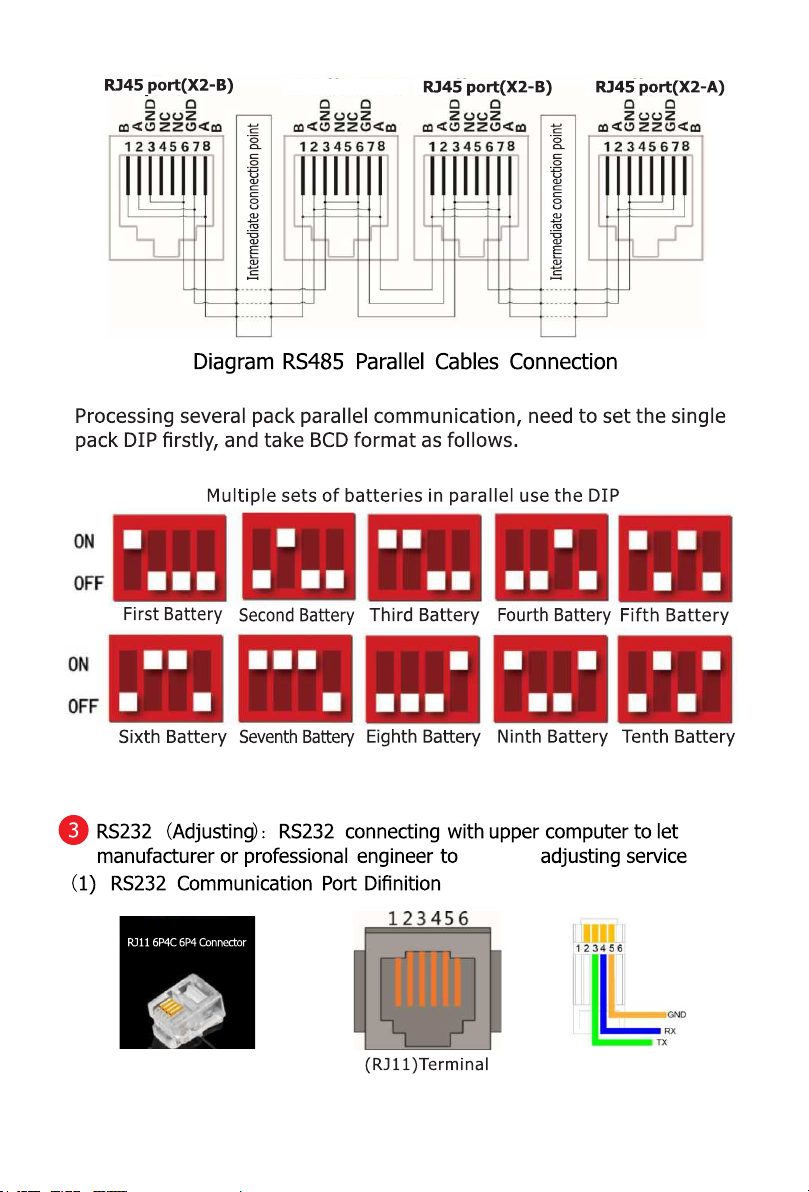
2.3 Equipment interface instruction
7 ADDS:DIP switch setting instructions
8 9 10
6 7 11 5421
312
-

6
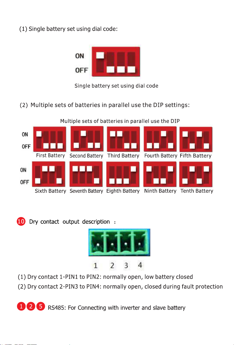
7
8
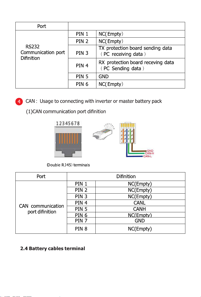
Port
1.Under parallel status, Communication address 0001 is Master
battery pack, rest communication position are slave battery. And
slave battery could communication with master battery pack through
RS458 port. master battery pack will collect all slave battery data.
(1)
2.When parallel status, only master battery pack communicate with PC
upper computer as remote monitoring, uploading datas, displaying status
& any other info of all battery packs.
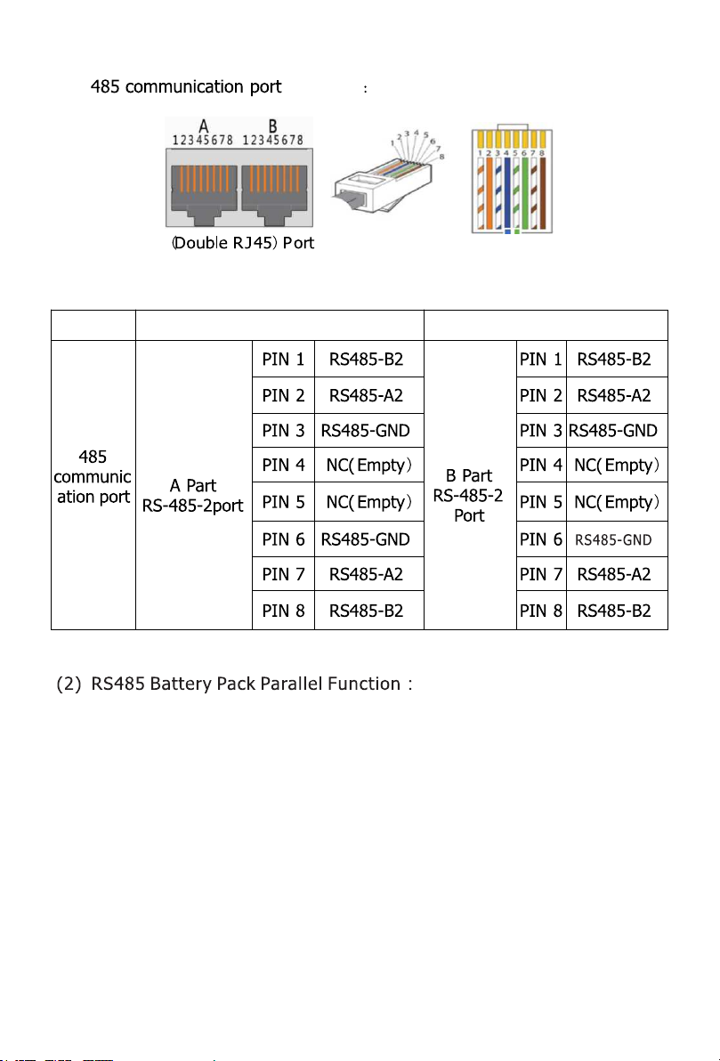
definition
Definition Definition
definition
9
RJ45 port(X2-A)
process
10
Clarifying
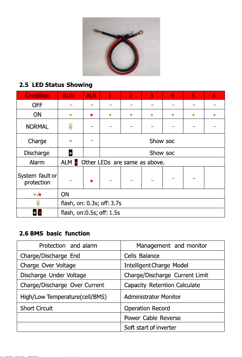
Put the OT connector on battery terminal to fix it.
11
Battery Module
Public Grid
Local Load
PV ARRAY
Inverter
12

It is recommended to wear the following safety gear when dealing with
the battery pack.
4.1 Package Items
Unpack and check the pakcing list
(1) For battery module package:
①Single battery pack stanard package:1pc orange and black waterproof
terminal and OT(100A)
4. Installation and Operation
13
②Could be customization per require:battery cable、communication cable、
parallel cable、grounding cable.

14
(2) For battery system connecting to inverters:
Two long power cables (current capacity 120A, constant 100A) and one
communication cable for each energy storage system:
4.2 Installation Location
Make sure that the installation location meets the following conditions:
(1)The area is completely water proof.
(2)The floor is flat and level.
(3)There are no flammable or explosive materials.
(4)The ambient temperature is within the range from 0°C to 50°C.
(5)The temperature and humidity is maintained at a constant level.
(6)There is minimal dust and dirt in the area.
(7)The distance from heat source is more than 2 meters
(8)The distance from air outlet of inverter is more than 0.5 meters.
(9)The installation area shall avoid of direct sunlight.
(10)There is no mandatory ventilation requirements for battery module,
but please avoid of installation in confined area.The aeration shall
avoid of high salinity, humidity or temperature.
If the ambient temperature is outside the operating range, the battery pack
stops operating to protect itself. The optimal temperature range for the
battery pack to operate is 0°C to 50°C. Frequent exposure toharsh
temperatures may deteriorate the performance and life of the battery pack.
15
Install a grounding cable to the grounding point of the modules.
4.4 Installation Instruction
Grounding cables shall be 10AWG or higher yellow-green cables. After connection,
the resistance from battery grounding point to Ground connection point of room
or installed place shall smaller than 0.1Ω.1)
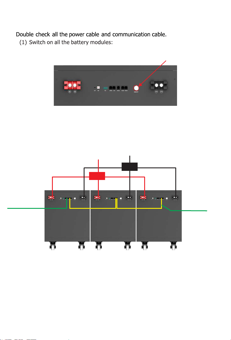
(1)Connect the cables to inverter.
(2)Connect the cables between battery modules.
16
(3)Press the red SW button of master battery to power on, all the battery
LED light will be on one by one from the Master battery.
(2)The one with empty Link Port 1 is the Master Battery Module, others are
slaves (1 master battery configure with maximum 15 slave batteries):
4.5 Power on
POSITIVE +
NEGATIVE —
BUSBAR
BUSBAR
Communication
Parallel Cables
CAN COMMUNICATION
Dial Code 1 Dial Code 2 Dial Code 3

17
Note:
(1) After the battery module powered on, the soft-start function takes 3sec
to active. After soft-starts battery ready to output high power.
(2) During capacity expansion or replacement, when parallel different
SOC/voltage of module together, please maintain the system in idle for
≥15mins or till the SOC LED becomes similarly(≤1dot difference) before
normal operation.
4.6 Power off
(1) Turn external power source off.
(2) Press red SW switch of master battery. Then all batteries will off.
(3) Turn off the power switch .
4.7 Multi-group mode
Connect power cable first:
(1) each pair of cable hold max 100A constant current. Connect enough pairs of
cable based on calculation of system current.
(2)Suitable protection breaker between battery system and inverter is required.
(3) Make sure all dip switch of master batteries are R 0XX, then turn ON batteries.
R: is the baud rate of RS485 needed, all master batteries shall be the same.
(4) After all batteries running and buzzer of master battery in group1 rings 3
times.Means all groups are online.
The interruption of each RS485 command shall at least≥1s.

18
Problem determination based on:
(1) Whether the battery can be turned on or not.
(2) If battery is turned on, check the red light is off, flashing or lighting.
(3) If the red light is off, check whether the battery can be
charged/discharged or not.
Possible conditions:
(1) Battery cannot turn on, switch ON and press the metal SW the lights
are all no lighting or flashing.
(1.1) Capacity too low, or module over discharged.
solution: use a charge or inverter to charge battery. If battery can
start, then keep charge the module and use monitor tools to check
the battery log.
If battery terminal voltage is ≤2.8V/cell, please use ≤0.05C to slowly
charge the module to avoid affect to SOH.
If battery terminal voltage is >2.8V/cell, it can use ≤0.5C to charge.
If battery cannot start, turn off battery and repair.
(2)The battery can turn on, but red light is lighting, and cannot charge or
discharge. If the red light is lighting, that means system is abnormal,
please check values as following.
(2.1)Temperature: Above 60 ℃ or under -10 ℃, the battery could not work.
Solution: to move battery to the normal operating temperature range
between 0℃ and 50℃.
(2.2)Current: If current exceeds 100A, battery protection will turn on.
Solution: Check whether current is too large or not, if it is, change the
settings on power supply side.
(2.3)High Voltage: If charging voltage is over 3.65V per cell, battery
protection will turn on. Solution: Check whether voltage is too high
or not, if it is, to change the settings on power supply side. And
discharge the battery.
5.Trouble shooting
Table of contents
Other Must Batteries Pack manuals

Popular Batteries Pack manuals by other brands


TCW Technologies
TCW Technologies IBBS-12v-6ah-CRT-V manual

Enerdrive
Enerdrive DOMETIC B-TEC LITHIUM EPL-200BT-12V-SLIM owner's manual

FujiFilm
FujiFilm EF-BP1 owner's manual

Sunoptic Surgical
Sunoptic Surgical LLS-2054BE Operator's manual

Radio Shack
Radio Shack 23-288 quick start guide

Optika
Optika M-069 instruction manual


