Hensel-Visit COPY ONE User manual

U S E R M A N U A L
COPY ONE
Flash Head

User manual Copy One
2 HENSEL-VISIT GmbH & Co. KG
HENSEL-VISIT GmbH & Co. KG
Robert-Bunsen-Str. 3
D-97076 Würzburg
GERMANY
Tel. +49 (0) 931 27881-0
Fax: +49 (0) 931 27881-50
Internet: http://www.hensel.de
© HENSEL-VISIT GmbH & Co. KG, 2018
Distribution and duplication of this documentation is not permitted unless
specifically authorized. Violation of this may result in payment of
damages.
All rights, including rights created by patent grant or registration of a
utility model or design, are reserved (DIN ISO 16016).
Subject to technical changes. Errors and omissions excepted. The listed
data are guideline values and not to be regarded as guaranteed values in
a legal sense. Values can deviate due to tolerances of construction parts.
900.0518.01

User manual Copy One
HENSEL-VISIT GmbH & Co. KG 3
For Your Safety
This device was developed according to the latest standards of technology
and manufactured, with greatest care and testing, from high-quality
material.
However, its use can result in bodily injury and property damage.
Please note the general safety guidelines and warnings that precede each
use when operating this device. Please read all of the enclosed
instructions.
Please note the warnings in the documents and on the device.
Only use the device when it is in proper condition. Be aware of safety
precautions and possible danger.
Keep this document available with the device.

User manual Copy One
4 HENSEL-VISIT GmbH & Co. KG
Safety Precautions and Warning Notices
The warning notices are marked with the following danger icons and
signal words according to severity:
Danger icon
Signal word
Explanation
DANGER
Warning of danger which can lead to
major or fatal injuries if disregarded.
WARNING
Warning of danger which can lead to
major or fatal injuries if disregarded.
CAUTION
Warning of danger which can lead to
injuries if precautions are disregarded.
CAUTION
Warning of danger which can lead to
property damage if disregarded.
Structure of Warning Notices
Warning notices are indicated by separation lines above and below. They
are structured according to the following principle:
SIGNAL WORD
Type and Source of Danger
Explanations of the type and source of danger
Measures to avert danger

User manual Copy One
HENSEL-VISIT GmbH & Co. KG 5
Basic Safety Instructions
Safety Hints Pertaining to Emitted Optical Radiation
Electrical power is changed inside the flash tube to intensive optical
radiation:
Do not flash directly into eyes from a short distance because the
emitted intensive optical radiation can cause eye and skin damage.
Do not look directly into flash reflector; the flash may be
accidentally triggered.
In case of damage to skin or eyes caused by intensive optical
radiation consult a physician immediately.
Working in Potentially Explosive Rooms
Working in potentially explosive rooms and environments is prohibited
because small sparks develop upon triggering the flash.
Never work in potentially explosive environments.
Do not work near flammable material.
Do not store flammable material in direct vicinity of flash generators
and flash lamps to avoid fire hazards.
Ozone Formation
Closed rooms must be ventilated frequently to prevent excessive ozone
formation which can result from to the use of strong flash units.
Acclimatization
Sudden changes in temperature, e.g. during transportation in a car, can
lead to condensing water in the flash unit. This can lead to severe
technical damage.
Let the flash unit acclimatize turned off for a longer period of time in the
new environment. This will evaporate the condensing water which has
eventually formed inside the flash unit.

User manual Copy One
6 HENSEL-VISIT GmbH & Co. KG
Protecting Equipment from Moisture and Splash Water
Flash units need to be protected from high humidity, moisture, wetness
and splash water. Therefore, please do not place containers with liquids
on the flash units.
Take care that neither the flash unit nor the flash or mains cable is lying
on a wet floor.
Connecting Accessories
Do not connect accessories from other manufacturers, even if these look
similar or identical.
Not in Use During Dust Development
Equipment that is not in use when doing work that results in strong dust
development needs to be covered with suitable dust protection.
Safety Hints Pertaining to the Electrical System
Contact with the flash generator’s capacitor voltage is life threatening.
Therefore, opening the housing and repairs may only be done by
authorized customer service personnel:
Never open the device –high voltage, risk of death!
The unit may only be connected to a power supply with working
equipment grounding conductor.
Use only lamp plugs with flawless contacts. Burned down or
corroded plug contacts may cause a fire.
Defective plugs may lead to defective plug sockets.
To prevent damages, avoid leading cables across floors. If this
cannot be avoided, make sure that the cable is not damaged by
vehicles, ladders, etc. Damaged cables and housings need to be
replaced immediately by authorized customer service personnel.
Explosion of Flash Tube
The flash tube is filled with xenon gas. There is negative pressure inside
the flash tube. Plasma develops during flashing due to electrical energy

User manual Copy One
HENSEL-VISIT GmbH & Co. KG 7
being changed to radiation. This plasma development then causes
positive pressure inside the flash tube. At the same time, the glass tube is
exposed to strong mechanical forces. Minimal defects of the fused quartz
glass, visually impossible to notice, may possibly lead to the explosion of
the flash tube.
In case the flash tube explodes, there is a danger of tiny glass
particles flying around. The user of this equipment needs to make
sure to protect himself by the use of the front diffuser.
The flash tube can only explode during the flash process.
Therefore, the flash head should never be directed at a person
during flashing.
Immediately disconnect the flash head from the generator if the
flash tube becomes damaged. Electrodes carry high voltage!
Flash tubes must only be changed by authorized and trained
personnel.
The flash tube must only be changed after the device is
disconnected from the power supply and is completely discharged.
Risk of Burns from Reflector and Flash Unit
After flashing there is a risk of burns caused by the reflector and the flash
unit due to hot parts on the housing or infrared heat radiation.

User manual Copy One
8 HENSEL-VISIT GmbH & Co. KG
Preface
Dear customer,
By purchasing a Copy One Flash Head, you have selected a high quality
and high performance product.
Below, we want to give you some details and hints on how to use this unit
that will ensure successful and productive work with it in the coming years.
Observing the information below entitles you to guarantee adjustments,
prevents damages, and extends the operational life of the unit.
HENSEL-VISIT made all efforts to produce a safe and high-quality piece of
equipment while observing all current rules and regulations. Stringent
quality checks ensure our high quality standard even in large-scale
production. Please do your part and treat the equipment with the
necessary care.
In case of questions regarding the use of this equipment, feel free to call
us any time.
HENSEL-VISIT GmbH & Co. KG

User manual Copy One
HENSEL-VISIT GmbH & Co. KG 9
Table of Contents
For Your Safety................................................................................... 3
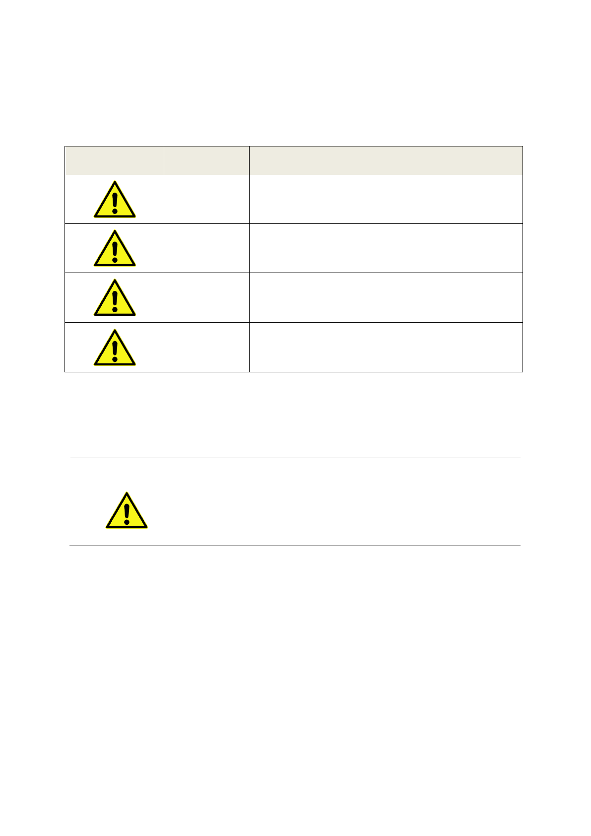
Safety Precautions and Warning Notices .................................... 4
Structure of Warning Notices..................................................... 4
Basic Safety Instructions ...................................................................... 5
Safety Hints Pertaining to Emitted Optical Radiation .................... 5
Working in Potentially Explosive Rooms ...................................... 5
Ozone Formation..................................................................... 5
Acclimatization......................................................................... 5
Protecting Equipment from Moisture and Splash Water................ 6
Connecting Accessories ............................................................ 6
Not in Use During Dust Development ........................................ 6
Safety Hints Pertaining to the Electrical System ............................ 6
Explosion of Flash Tube ............................................................ 6
Risk of Burns from Reflector and Flash Unit................................. 7
Preface .............................................................................................. 8
Description of Service ....................................................................... 11
Proper Use............................................................................. 11
Following the Instructions........................................................ 11
Technical Data ................................................................................. 12
Equipment Description...................................................................... 13
Scope of Delivery.............................................................................. 13
Initial use of system .......................................................................... 14
Stand Mounting................................................................................ 14
Mounting to Lamp Support................................................................ 15
Proper Use............................................................................. 16
Maintenance Plan............................................................................. 18
Cleaning ......................................................................................... 18

User manual Copy One
10 HENSEL-VISIT GmbH & Co. KG
Periodic Safety Checks ...................................................................... 18
Customer Service ............................................................................. 19
Disposal .......................................................................................... 19
Accessories ...................................................................................... 19
Contact Information ......................................................................... 20
Warranty ......................................................................................... 21
Limits of Liability..................................................................... 21

User manual Copy One
HENSEL-VISIT GmbH & Co. KG 11
Description of Service
Via a flash cable the flash head Copy One has to be connected to a
Hensel power pack of the Nova D series or Porty L series.
The flash head Copy One can be swivelled smoothly via the lamp bracket.
The flash head can be mounted with optional holders on a lamp support
from Kaiser Fototechnik
The 3/8“ thread integrated in the lamp bracket lets you attach the Copy
One flash head to all common lamp stands.
Proper Use
The flash head Copy One is used together with Hensel series Nova D and
Porty L flash generators, but it can also be adapted for use with older
Hensel generators
The system was jointly developed by company Hensel-Visit and company
Kaiser Fototechnik for the professional lighting of originals in the scope of
photographic reproduction.
The short flash duration times of the integrated flash prevent a loss of
resolution caused by shaking or vibrations, and the use of short sync times
eliminates color shifting, incorrect exposure, and ambient light reflections.
The ample reserves of flash generators easily allow for the use of light
absorbing filters, e.g. for images with polarized light or in the infrared
range.
The Copy One flash heads are also equipped with an efficient LED
modeling light that is suited for video recordings.
Furthermore, it can be used in other areas, like product photography or
for the lighting of photographic backgrounds.
Following the Instructions
Following the instruction manual and all other pertinent documents is part
of the intended use.

User manual Copy One
12 HENSEL-VISIT GmbH & Co. KG
Technical Data
Unit series / Unit type
Copy One
Article number
9800
Maximum flash power
1,200 J
Continuous light power
Max. 21 W LED (≈ 200 W Halogen)
Setting range
Up to 8 f-stops in 1/10 steps
(depending on generator)
Flash duration
1/4,500 –1/1,000 s (depending on
generator and flash power)
Color temperature
5400 K
Fidelity Index Rf
98 –97
Gamut Index Ra
100
CIE Ra
98 –96
Light output area
21 x 63,5 cm
Lamp connector
Round plug for Hensel Nova D and
Porty L (Long plug for Nova DL und Tria
with optional adapter)
Lamp cable length
5 m
Operating voltage
110 V / 60 Hz and 230 V / 50 Hz
(depending on flash generator)
Dimensions
64,5 x 22,0 x 10,5 cm
(W x H x L, only lamp)
Weight
4,5 kg
(incl. cable without supporting arm)
Technical modifications excepted.
The listed data are standard values which may deviate depending on component tolerances.

Bedienungsanleitung Copy One
Hensel-Visit GmbH & Co. KG 13
Equipment Description
Front diffusor
Flash head cable
Opening for air ventilation
Threads for lamp support
connectors
Thread for stand mounting
Lamp bracket
Thread for lamp support connector
Label with safety instructions
Type label
Flash cable to the generator
Scope of Delivery
The standard scope of delivery includes:
1 Copy One Flash Head with integrated lamp bracket
1 User Manual

Bedienungsanleitung Copy One
14 HENSEL-VISIT GmbH & Co. KG
Initial use of system
CAUTION
System may get damaged
The system can be damaged during connecting to the
power supply.
Check listed mains supply on type label of the
unit.
Only connect to grounded power supply.
Plugs must be secured at building side with 16
A at 230 V and with 20 A at 110 V.
Make sure that the generator to which you want to connect the flash head
to is switched off and disconnected from the mains.
Stand Mounting
WARNING
Danger of bruising
When opening the locking screws you are in danger
of bruising your hands and fingers.
When opening the screw of the tilting bracket,
hold the flash unit with the other hand to avert
unwanted motion.
Thread
Stand spigot
Screw the spigot of the stand
into the thread on the lamp
support of the flash head.

Bedienungsanleitung Copy One
Hensel-Visit GmbH & Co. KG 15
Mounting to Lamp Support
Please note: For the mounting onto a lamp support you need the optional
lamp support holders (code no. 99565002 ), see chapter “Accessories”
on page 19.
WARNING
Danger of bruising
When opening the locking screws you are in danger
of bruising your hands and fingers.
When opening the screw of the tilting bracket,
hold the flash unit with the other hand to avert
unwanted motion.
Locking screw of the lamp bracket
connector
Loosen the locking screw of
the lamp bracket connector,
put it on the thread of the
lamp bracket and tighten the
locking screw again.
Locking screw of the holders for
the lamp support
Lamp support
Loosen the locking screws of
both holders and slide the
openings onto the lamp
support.
Tighten the locking screws of
the holders.

User manual Copy One
16 HENSEL-VISIT GmbH & Co. KG
Proper Use
For classic reproduction work, it is important to light the originals
homogeneously and with equal light intensity by using two Copy Ones,
one to the left and one to the right of the original and set at the same
angle (typically 45°). We recommend the use of a light meter with a flat
calotte to check lighting and light intensity.
Each Copy One lamp can be set up to 1200 Ws, even though this is
normally not necessary. Due to the high effectiveness of professional flash
units, it is usually sufficient to operate the generator at the low or medium
power ranges to use advantageous f-stop values and to avoid diffraction.
If the Copy One overheats despite this, the head will be deactivated
automatically and can be used again after cool down.
The brightness of the modeling light of Nova D and Porty L generators is
proportional to the selected flash power. For better image checks, the
modeling light can be switched to “MAX“ on the generator. Please note
that the LED modeling light can affect the lighting when pictures are taken
with very low flash power and/or longer sync times –in such cases, the

User manual Copy One
HENSEL-VISIT GmbH & Co. KG 17
modeling light should be deactivated on the generator prior to picture
taking.
The flash head Copy One is used together with Hensel series Nova D and
Porty L flash generators, but it can also be adapted for use with older
Hensel generators.
If only continuous light is used –like in videography –its intensity can be
controlled with the generator‘s power control (modeling light mode
“PROP“). Deactivate the slave and, if applicable, the radio sync of the
generator to prevent accidental flash triggering during recording.
Accessory barndoors are available for Copy One. These help control the
light distribution and prevent light scatter and thus appearing reflections.
The barndoors are also equipped with clips that make it much easier to
securely attach filter foils.

User manual Copy One
18 HENSEL-VISIT GmbH & Co. KG
Maintenance Plan
Clean the system regularly as described in the section ’Cleaning’. Please
lubricate the locking bolt thread every 1-2 years.
Cleaning
DANGER
Danger of electric shock
Danger of electric shock exists during installation and
removal of system components.
Switch off unit via the power switch.
Disconnect the unit from the mains voltage.
Wait 15 minutes for the discharge of the
capacitors.
CAUTION
Risk of burns from reflector and flash unit
Heat which may cause burns develops at the head
during the flash process.
Before removing the reflector allow reflector
and flash unit to cool off.
The flash unit needs little maintenance by the user. The outside of the
equipment must be cleaned periodically with a dry cloth of dust and dirt to
ensure electric safety.
Periodic Safety Checks
The national health and safety at work regulations - BetrSichV and DGUV
Regulation 3 (formally known as BGV A3) –mandate periodic checks and
maintenance of electrical systems and devices. Generators and
accessories must be checked regularly for operational safety. A yearly
check of devices serves to ensure user safety and retains system value.
The above mentioned regulations apply to the whole EU area. If you live
outside the EU, please observe your local regulations.

User manual Copy One
HENSEL-VISIT GmbH & Co. KG 19
Customer Service
Keep the original packing material in case shipment becomes necessary.
It provides maximum protection during transport.
If shipment to our customer service department becomes necessary, send
the equipment to the below listed address for repairs and include a
description of the problem:
HENSEL-VISIT GmbH & Co. KG
Service
Robert-Bunsen-Str. 3
D-97076 Würzburg
Phone number: +49 (0)931/27881-0
Disposal
The packing material must be separated and recycled. At the end of its life
cycle, this product may not be discarded in regular household waste but
must be turned in at a recycling station for electrical and electronic devices
according to WEEE regulation and ElektroG 20/10/15. You contribute to
environmental safety by recycling material and devices.
The above mentioned regulations apply to the whole EU
area. If you live outside the EU, please observe your local
regulations.
Accessories
Description
Code no.
Barn doors, 2 pcs. for 1 Copy One
9801
Repro holder set with lamp support, for 2 Copy One
99565002
Adapter for Hensel Tria generators
5781

User manual Copy One
20 HENSEL-VISIT GmbH & Co. KG
Contact Information
In case of questions concerning the shipment for repair reasons, for
orders, or for questions about the equipment please contact us at:
Internet: vww.hensel.de
Email: info@hensel.de
Telephone: +49 (0)931/27881-0
Fax: +49 (0)931/27881-50
Mail: HENSEL-VISIT GmbH & Co. KG
Robert-Bunsen-Str. 3
D-97076 Würzburg
In case of questions concerning the accessories for repro photography,
please contact us at:
Internet: www.kaiser-fototechnik.de
E-Mail: info@kaiser-fototechnik.de
Telefon: +49 (0)6281/4070
Fax: +49 (0)6281/40755
Post: Kaiser Fototechnik GmbH & Co. KG
Postfach 1262
D-74711 Buchen
Table of contents
Other Hensel-Visit Work Light manuals
Popular Work Light manuals by other brands

ZAZU
ZAZU Fin the Sheep quick guide

Griven
Griven nanoParade AL4484 user manual

Philips
Philips LivingColors 6917130PH brochure

Setolite
Setolite ALDEBARAN 360 GRAD FLEX-C 2.0 Instructions for use

Styro
Styro Hansa LED 4 Stars operating instructions

Halla
Halla Sineli 230-7 1-15G Series installation instructions