Heritage Glastonbury SGSIN05 User manual

Instaation
Guide
Models Covered:
Sequential and Concentric
Exposed Shower Valves
Please keep this booklet for future
reference.
Installer: When you have read these
instructions, please ensure you leave them
with the user.

2
INTRODUCTION
Thank you for buying a Heritage Product. When you buy a Heritage product, you can be condent
that it not only features a beautiful, distinctive, classic design, but that it has also been made to the
very highest quality standards.
To ensure that it works to its full potential, it needs to be tted correctly.
These tting instructions have been created to give you all of the information you need and, if you
need any further help, please do not hesitate to give us a call on: 0330 026 8503.
CONTENTS
SAFETY NOTES 3
SPECIFICATION 4
INSTALLATION REQUIREMENTS 5-7
PRIOR TO INSTALLATION 8-9
TOOLS REQUIRED 10
INSTALLATION 10-11
O P E R AT I ON 11
MAINTENANCE 12-17
TROUBLESHOOTING 18
CARING FOR YOUR PRODUCT 19
GUARANTEE 19
NEED HELP? 19

3
Please make sure you read these instructions and retain for future use.
All products manufactured by Heritage Bathrooms are safe, providing they are installed and used
correctly and also receive maintenance when needed.
These ttings, including the connecting water and waste system need to be installed in accordance
with and meet the requirements of the Water Supply Regulations 1999 (Water Fittings) and current
by-laws. If you are in doubt about your ability to install this product correctly or safely, you should
employ the services of an experienced qualied plumber.
This product must not be modied in any way otherwise this will invalidate the guarantee.
Remove all packaging and check the contents for damage before starting installation.
Warning: Before installing the new mixer valve it is essential that you thoroughly ush through the
pipework in order to remove any remaining swarf, solder, etc. Failure to carry out this
procedure could cause problems or damage to the workings of the mixer tap.
Fitting isolating valves to the inlet feeds is required for ease of maintenance.
Warning: Do not operate the mixer if you suspect it is frozen. Do not site the mixer valve
where it might be subjected to freezing conditions.
Consider the following whilst using power tools:
• Prior to drilling into walls, check there are no hidden electrical cables or wires and
there are also no water pipes. These can potentially be found using an electrical or
metal detector. You may also need to know some of the schematics of previous
installations to determine the suitability and accommodation of the installation.
• Wear the correct PPE, especially ear, eye and hand protection
when using power tools. Unplug any mains equipment after use.
• Keep electrical equipment away from sources of water.
• If a blow-lamp is used when plumbing, the ame must be kept well away from
the product otherwise damage may occur.
If in doubt, contact a registered plumber, your Local Water Authority or the Secretary of The Institute
of Plumbing, address as follows;-
The Institute of Plumbing,
64 Station Lane,
Hornchurch,
Essex, RM12 6NB
Tel:01708 472791
SAFETY NOTES
4
SPECIFICATION
Recommended Usage
Domestic Heavy
Commercial
Light
Commercial Health Care
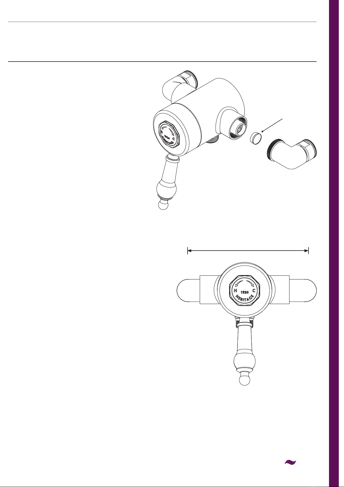
Shower Valve:
Inlet connection: 15mm compression with 135-158mm adjustable centres.
Outlet connection: G 1/2”
Operating pressure range: Min. 0.1 Bar - Max. 5.0 Bar
Maximum recommended imbalance between hot and cold supply should not exceed a ratio of 5:1.
Maximum Static Pressure: 10 Bar
System Requirements: Suitable for all plumbing systems
Note: Nominally equal (balanced) inlet supply pressures are recommended for optimum performance.
If the tting is installed at low pressure (tank fed), then the minimum distance from the outlet to the
underside of the cold tank should be at least 1 metre to ensure adequate performance
Supply Requirements:
Minimum cold water supply temperature: 5°C.
Maximum cold water supply temperature: 25°C.
Maximum hot water supply temperature: 80°C.
BS 8558 recommends hot water should be stored and distributed at a temperature of not less than
60°C which will help minimise the build-up of lime scale in hard water areas.A maximum hot water
supply temperature of 60 - 65°C is recommended for ablutionary purposes.
Note:The inlet hot water temperature must be at least 10°C above the required blend temperature
(eg. mixer temperature 41°C: minimum hot supply 51°C).
Maximum Outlet Temperature: Factory pre-set to 42°C
These showers are designed to be used in conjunction with Heritage shower kits.We cannot
guarantee compatability or adequate performance when used with other kits.This would also
invalidate your guarantee. Please refer to the installation manual supplied with your Heritage
shower kits for their specication information.
5
INSTALLATION REQUIREMENTS
This shower valve must be installed in compliance
with current water regulations. If you have any
doubts about the water regulation requirements
contact your local water services provider or use
the services of a professional plumber.
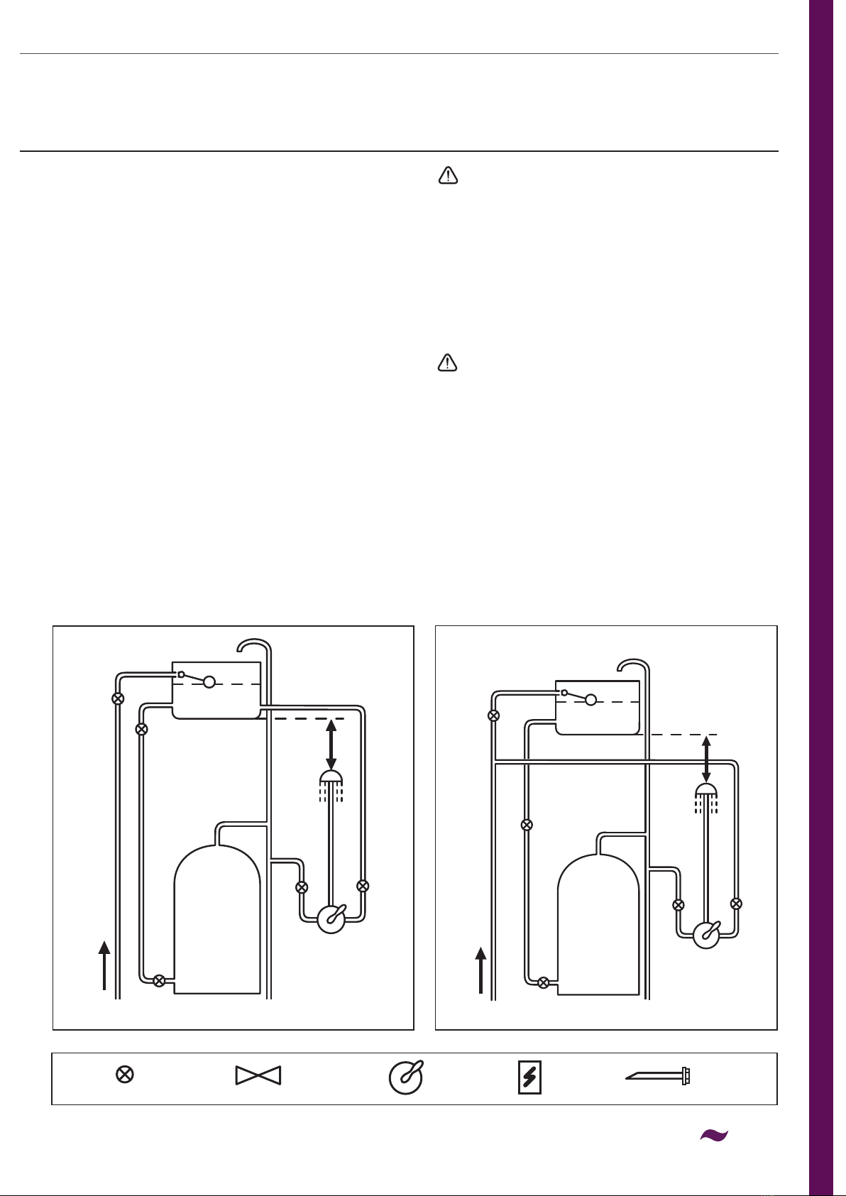
This shower valve is suitable for use with the
following water supply systems:
• Gravity Fed Hot and Cold
(pressure imbalance should not exceed
a ratio of 5:1 - see Specication section)
• Gravity Fed Hot and Mains Cold
(pressure imbalance should not exceed
a ratio of 5:1 - see Specication section)
• Instantaneous water heater
(combination boiler)
• Unvented System
• Pumped System
Gravity Fed Hot and Cold Gravity Fed Hot and Mains Cold
cold mains supply cold mains supply
Important: If you install this shower
valve with a gravity fed system, there must be
a minimum head (vertical distance) from the
underside of the cold water storage tank to the
outlet of at least 1 metre .
Note: Pumped system (with Essex ange)
If you install this shower valve to a pumped
gravity fed system where the minimum head
(vertical distance) from the underside of
the cold water storage tank to the top of
the hot water cylinder is less than 1 metre we
recommend an Essex ange is used as shown.
Flushing Pipe-work
Important: Before connecting the shower valve
(see ‘Installation’ on pages 11-12), the supply
pipe-work must be ushed to clear debris before
connecting the shower. Debris will reduce the
performance and life of the mixer.
1m min.
1m
min.
Key: Isolating
Valve
Reducing
Valve
Shower
Valve Pump Essex
Flange
6
INSTALLATION REQUIREMENTS
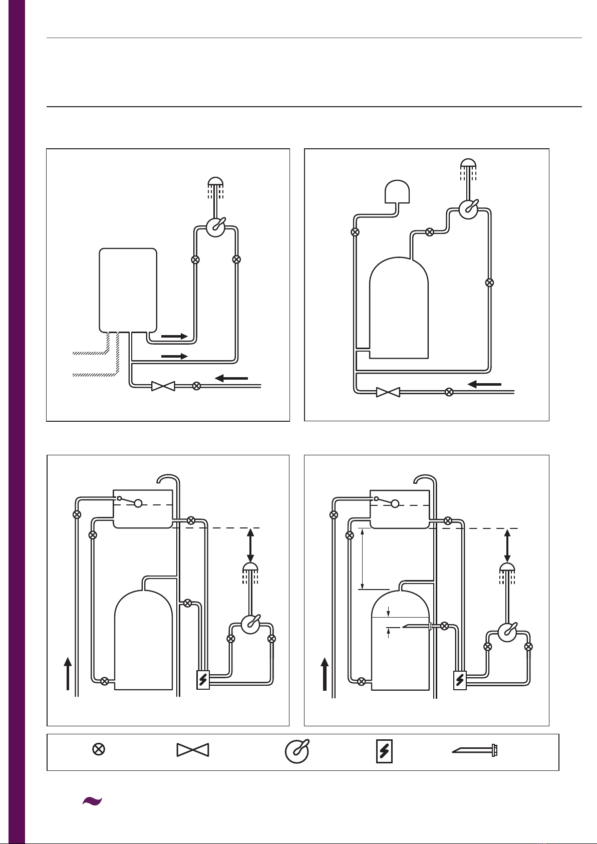
Unvented System
Instantaneous Water Heater
Pumped System
cold mains supply
cold mains supply
cold mains supply
Pumped System (with Essex ange)
cold mains supply
1m min.1m min.
50mm
If less
than 1m
see note.
Key: Isolating
Valve
Reducing
Valve
Shower
Valve Pump Essex
Flange

7
INSTALLATION REQUIREMENTS
This tting needs to be installed in accordance
with the following Installation Requirements
and Notes (IRN) to ensure they meet the
requirements of the Water Supply (Water Fittings)
Regulations 1999 and the Scottish Byelaws 2004.
IRN R001: See text of entry for Installation
Requirements or Notes.
IRN R040 - Schedule 2-15 (1): The tting shall be
installed so that its outlet discharges above the
spill-over level of any xed appliance as indicated
below:-
For backow protection in domestic or
installations up to, and including, Fluid Category 3.
If the tting cannot be installed as indicated in the
table opposite it shall be installed as either a or b
below:
a: with an approved double check valve assembly
or some other no less effective backow
prevention device immediately upstream of the
inlet.
b: so that it draws water by gravity only from a
cistern, or cylinder having a permanently open
vent pipe, and the distributing pipe supplies no
other ttings (other than a draining tap) at a
lower level.
For backow protection in premises or
installations up to, and including Fluid Category 5.
The vertical distance of the outlet above the spill-
over level shall be not less than 20mm or twice
the diameter of the inlet pipe to the tting, which
ever is the greater. If the tting cannot be installed
as indicated it shall be installed with a backow
prevention arrangement suitable for the Fluid
Category.
Size of tap or
combination tting
Vertical distance
of outlet above
spill-over level
1. Not exceeding ½” 20mm
2. Exceeding ½”
but not exceeding
¾”
25mm
3. Exceeding ¾” 70mm
8
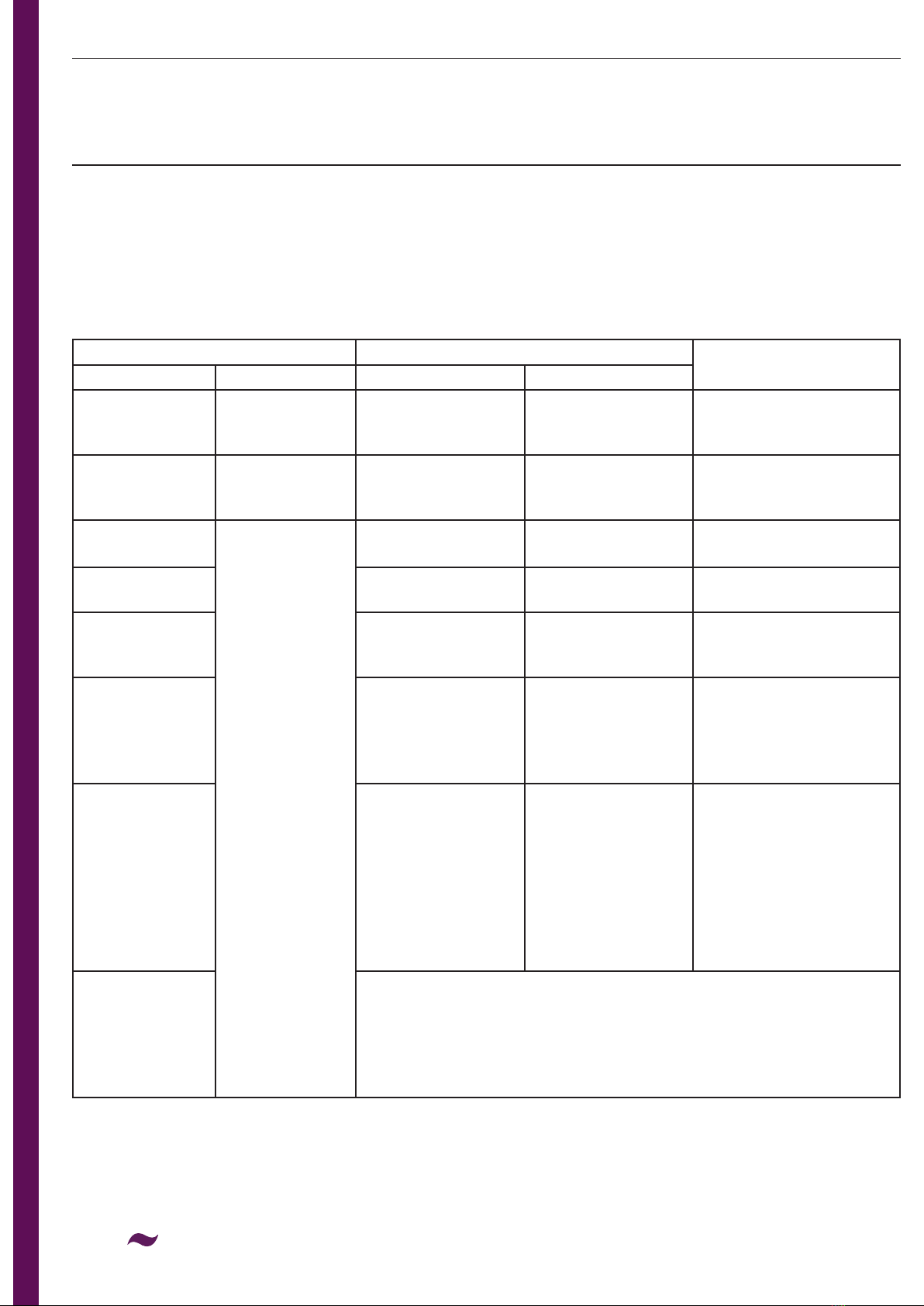
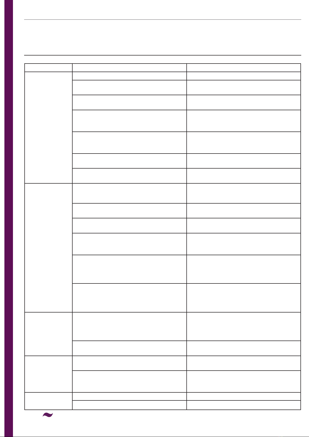
PRIOR TO INSTALLATION
Supply System Flow Regulator Comments
Hot Supply Cold Supply Hot Supply Cold Supply
0.1 - 1.0 bar 0.1 - 1.0 bar Not Required Not Required
Maximum pressure
loss ratio 5:1 between
inlets
1.0 - 5.0 bar
or pumped
1.0 - 5.0 bar
or pumped White (8 litre) White (8 litre)
Optional, can be used
if water economy
is required
Gravity Fed
0.1 - 0.5 bar
Mains 1.0 - 10
bar
Not Required White (8 litre)
Gravity Fed
over 0.5 bar White (8 litre) White (8 litre)
Unvented
Mains/ Mains
Pressurised
White (8 litre) White (8 litre)
Instantaneous
Water Gas
Heater
White (8 litre) White (8 litre)
It may not be
necessary on some gas
water heaters to have a
ow regulator on the
hot water supply.
Instantaneous
Water Electric
Heater
Not Required White (8 litre)
It is a requirement that
a stable ow of water
passes through the
heater. This can be
achieved by tting a
ow stabiliser before
the heater. The heater
temperature should also
be adjusted to 45-50°C
Any vented
(open outlet)
Heater
Gas/Electric
e.g.
Electric Shower
Do not use mixer valves with this type of water system;
this would be extremely dangerous!
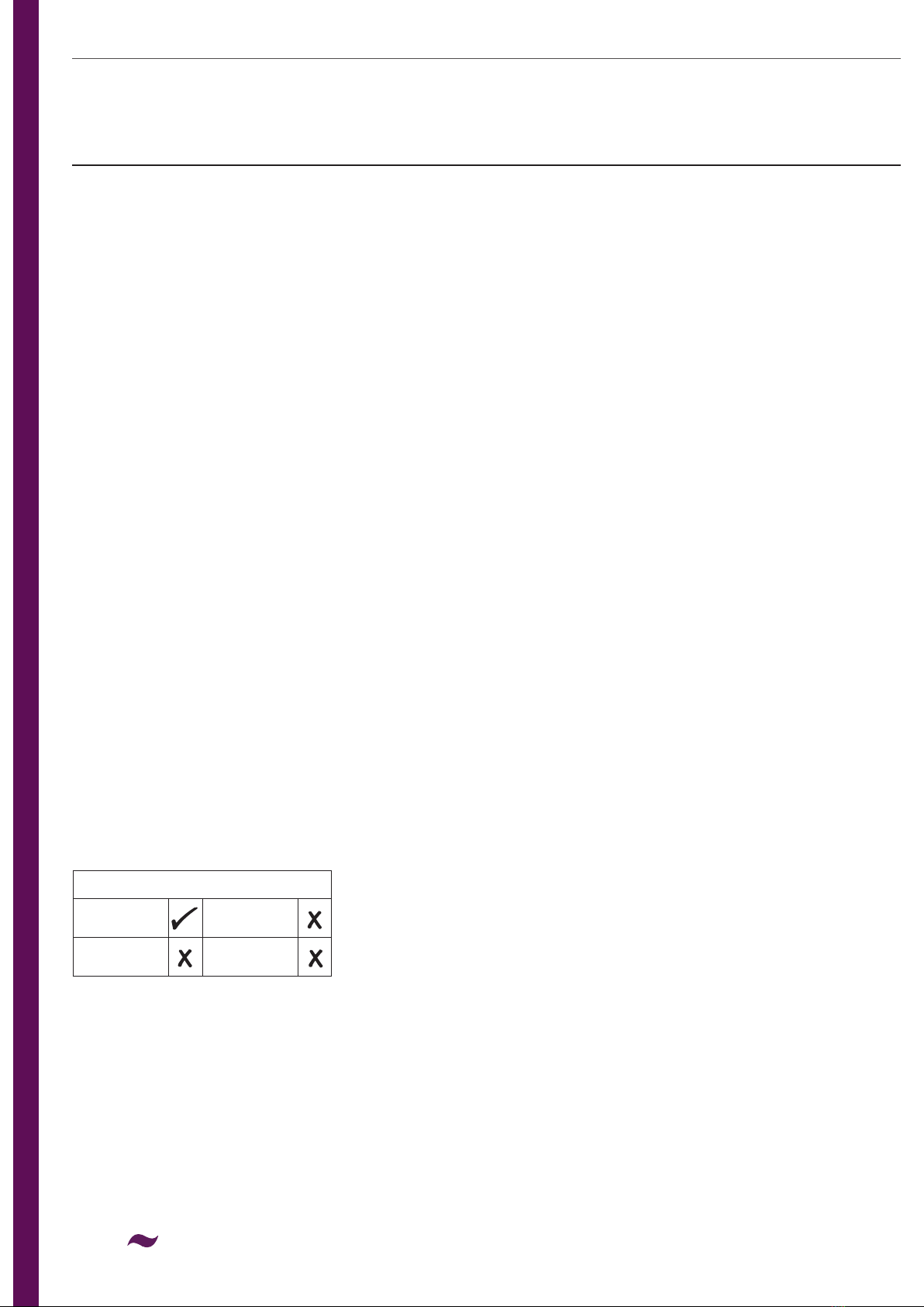
Two 8 litre per minute ow regulators have been pre-tted to this product for water efciency.
If you have low water pressure, or certain water supply systems these may need to be removed
in order to achieve adequate ow. Please see the table to check whether the ow regulators
need to be removed.
9
PRIOR TO INSTALLATION
1. Unscrew both inlet elbows
anti-clockwise from the valve
body.
2. Remove the ow regulators using
long-nosed pliers.
3. Screw the inlet elbows
clockwise to t back into
the valve body.
To Remove/Replace:
Conguring the Inlet Elbows:
The shower valve is supplied with elbows (pre
-tted) that can adjust between 135-158mm.
The elbows can be pointed to feed from the top,
bottom or rear.
Two full turns are required to t the elbow into
the body properly.
1. Unscrew both inlet elbows anti-clockwise from
the valve body.
2. Screw in the desired elbows clockwise for
two complete turns to t. This will set to
largest possible centre measurement.
3. The elbows can be screwed a maximum
of 1.5 turns after tting for adjustment.
Screw further clockwise to reduce the centre
measurement; anti-clockwise to increase.
To Adjust Elbows:
135-158
Centres
Flow Regulator
10
INSTALLATION
1. Prepare the 15mm water pipework, leaving
sufcient pipe protruding from the nished
wall to t into the elbows.
Flush through the pipework to
ensure removal of any debris.
Turn off the mains water
supply and close any
isolating valves.
Important: Water supplies to
the mixer must be with hot on
theleft and cold on the right
when viewed from the front.
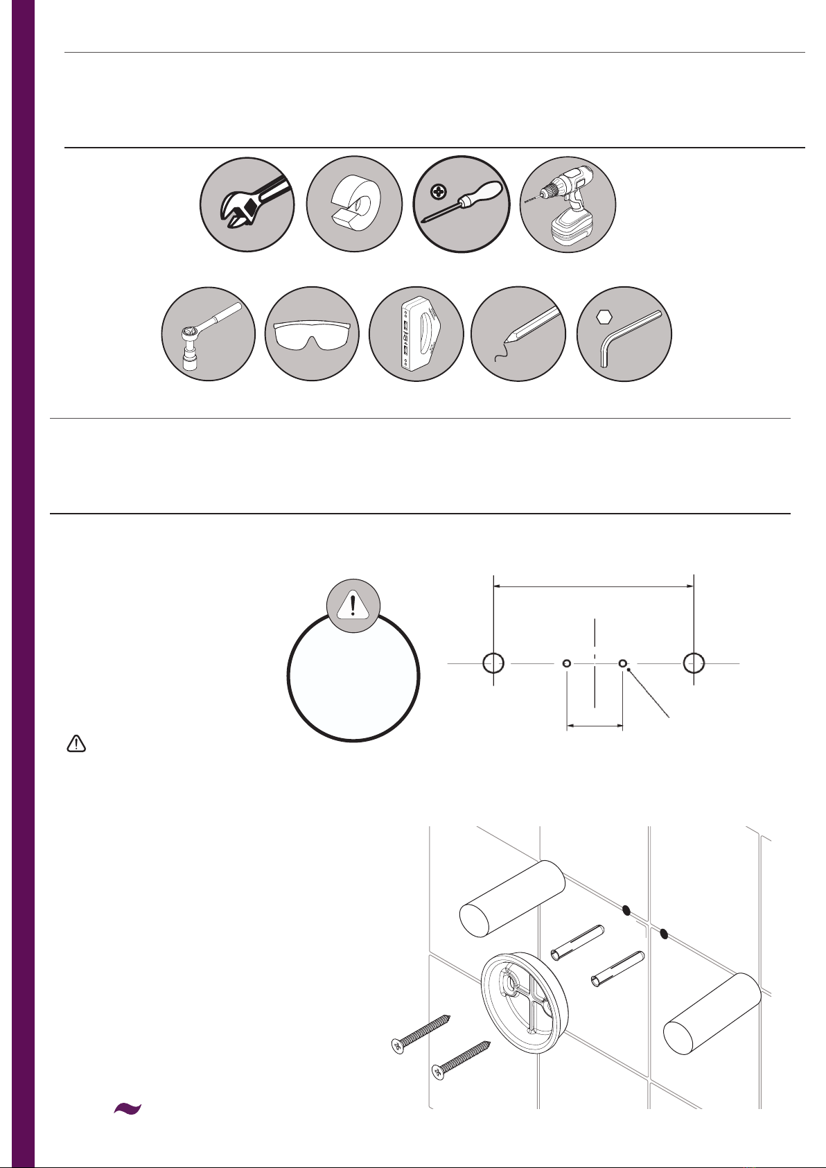
2. Measure the centre distance. Measure the
half-way point between the centres and
mark on the wall.
3. Congure the inlet elbows
to meet the centre distance.
4. Undo the grub screws at the back of the
shower valve to remove the backplate.
Place the backplate on the marked half-way
point between the centres and mark the
xing holes.
TOOLS REQUIRED
REMEMBER
Fit isolation
valves for future
maintenance.
135-158mm
Hot Cold
Backplate
Fixing
Holes
30-35mm
Pipe Cutter
Adjustable
Spanner
Cross Head
Screwdriver Drill
30mm
Socket Spanner Safety Goggles Electronic
Detector Pencil 2.5mm & 10mm
Hexagonal Keys
11
INSTALLATION
OPERATION
5. Drill the xing holes using a suitable drill bit.
A pilot drill will be required if drilling into tiles.
Insert the wall plugs and screw the backplate to
the wall.
Warning: Please check for any hidden
pipes and cables before
drilling holes into the wall.
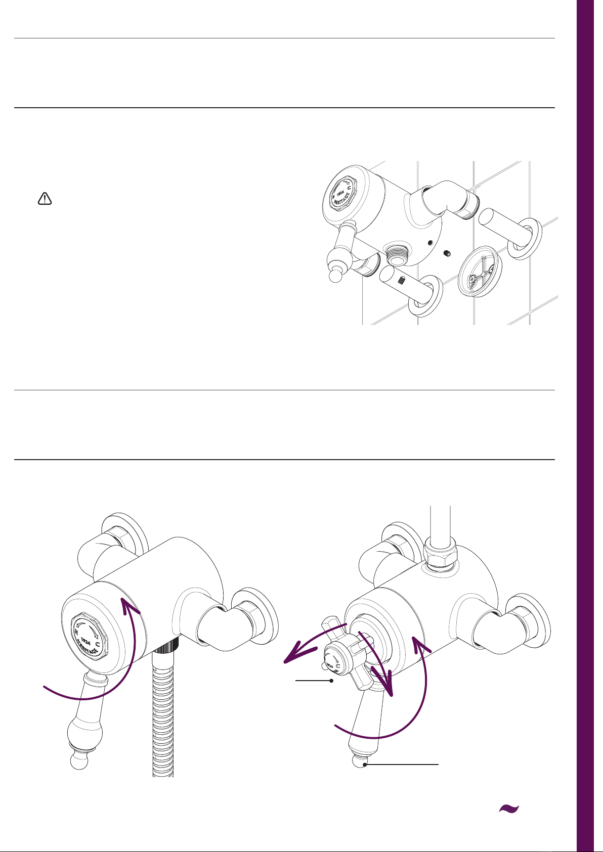
6. Place the plinths over the water supply pipes.
Feed the shower valve on to the water supply
pipes and tighten with the nut and olives.
Secure the valve to the back plate using the
grub screws.
Please refer to your shower kit instruction
manual to install the shower kit.
Flow Handle
Increase Flow
Increase
Temperature
and Flow
Hot
Off Off
Cold
Temperature
Handle
Sequential Shower Valves: Concentric Shower Valves:
12
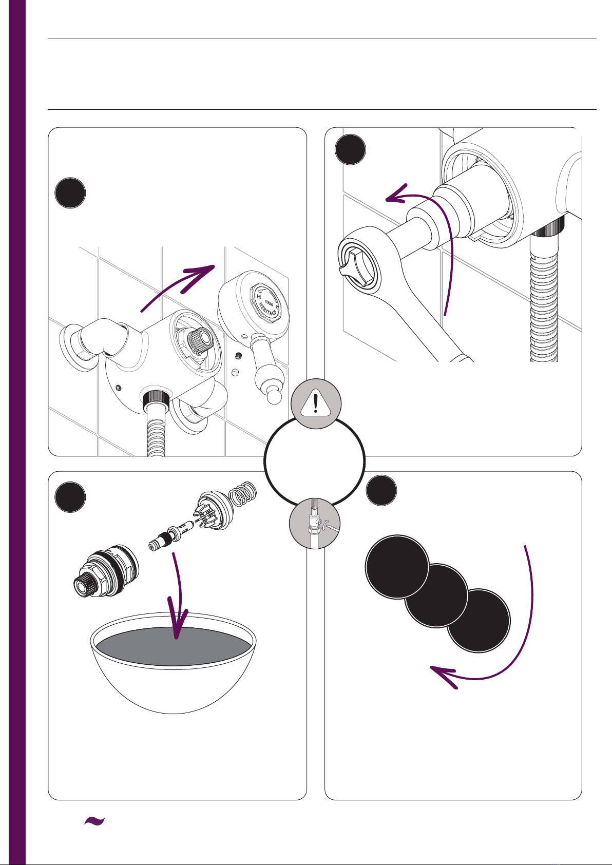
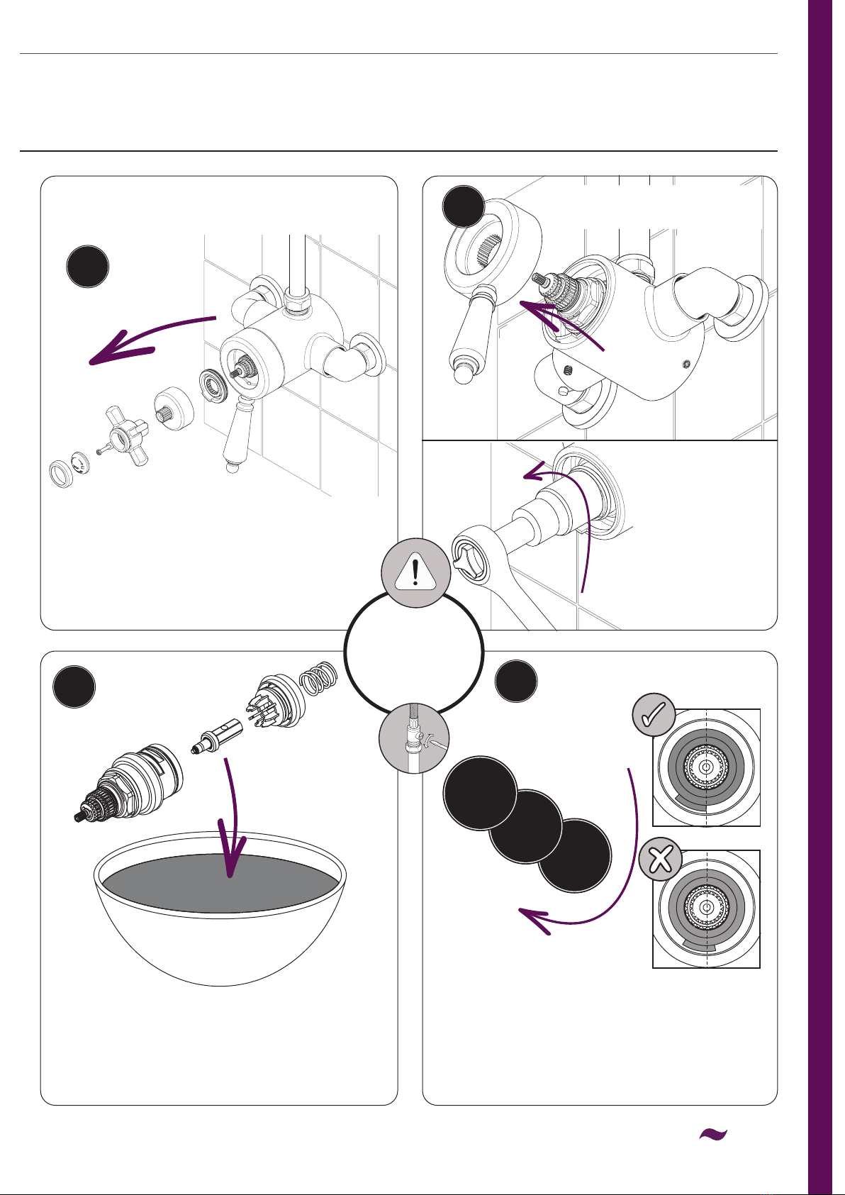
MAINTENANCE
Use a 30mm socket spanner to unscrew
the cartridge from the valve body.
Carefully remove the cartridge and spring.
Reverse the steps to re-t the cartridge and
handle. Reset the maximum temperature.
Remove all seals and check for any damage.
Place the cartridge in a suitable solution and
soak until fully de-scaled. Rinse thoroughly.
Replace all seals and grease with a
WRAS approved sealant.
Undo the grub screw to
remove the handle.
Replace/Clean Cartridge:
Sequential Shower Valves:
1
2
34
3
2
1
IMPORTANT
Isolate the
water supply
before starting!
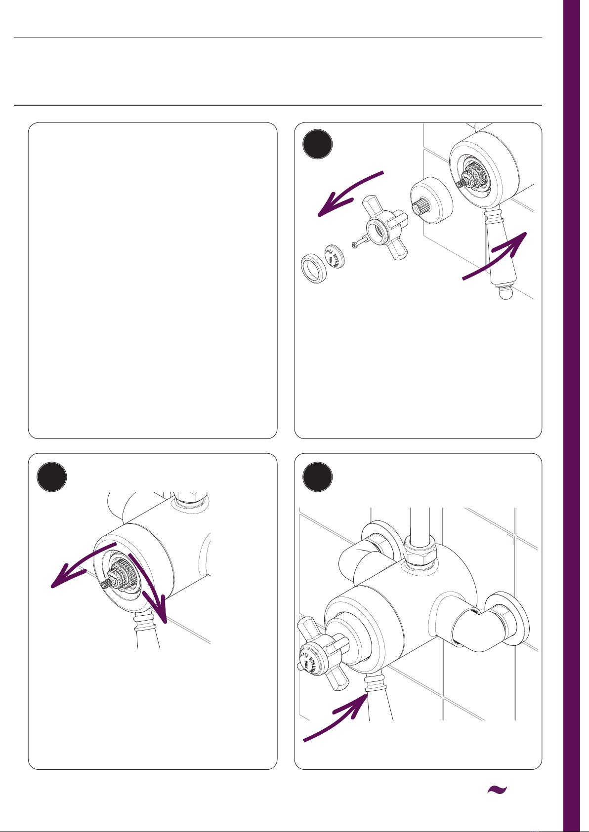
13
MAINTENANCE
Reverse the steps to re-t the cartridge and
handle. Ensure the temperature stop is tted
correctly. The stop should sit at the bottom
left, aligned centrally to the cartridge.
Reset the maximum temperature.
Remove all seals and check for any damage.
Place the cartridge in a suitable solution and
soak until fully de-scaled. Rinse thoroughly.
Replace all seals and grease with a
WRAS approved sealant.
Undo the indice housng and
unscrew the screw to remove the
temperature handle. Unscrew the
shroud and remove the
temperature stop.
Undo the grub screw to
remove the ow handle.
Replace/Clean Cartridge:
Concentric Shower Valves:
1
2
34
3
2
1
IMPORTANT
Isolate the
water supply
before starting!
Use a 30mm
socket spanner
to unscrew the
cartridge from
the valve body.
Carefully remove
the cartridge
and spring.

14
MAINTENANCE
The shower has been pre-set to 41°C.
This is based on being tted with nominally
balanced pressures with the hot water inlet
supply at 65°C. If your operating conditions
are different to the above your maximum
outlet temperature may differ.
We recommend setting the maximum
outlet temperature no higher than 43°C.
Using the 2.5mm hex key supplied,
adjust the temperature:
Turn the temperature handle to the
maximum temperature. Undo the grub
screw to remove the handle.
Re-t the temperature handle back in the
maximum temperature position.
Sequential Shower Valves:
Maximum Temperature Setting:
2 3
1
Wait for a couple of minutes for the
temperature to stabilise after adjusting.
Measure the water outlet temperature
using a thermometer. Adjust until the
desired temperature is reached.
Decrease
Temperature
Increase
Temperature
15
MAINTENANCE
Adjust the maximum temperature by
turning the spindle:
Turn the temperature handle to the
maximum temperature. Remove the
temperature handle and unscrew the
shroud. Turn on the shower.
Re-t the temperature handle back in
the maximum temperature position.
The shower has been pre-set to 41°C.
This is based on being tted with nominally
balanced pressures with the hot water inlet
supply at 65°C. If your operating conditions
are different to the above your maximum
outlet temperature may differ.
We recommend setting the maximum
outlet temperature no higher than 43°C.
Maximum Temperature Setting:
Concentric Shower Valves: 1
2 3
Wait for a couple of minutes for the
temperature to stabilise after adjusting.
Measure the water outlet temperature
using a thermometer. Adjust until the
desired temperature is reached.
Decrease
Temperature
Increase
Temperature
16
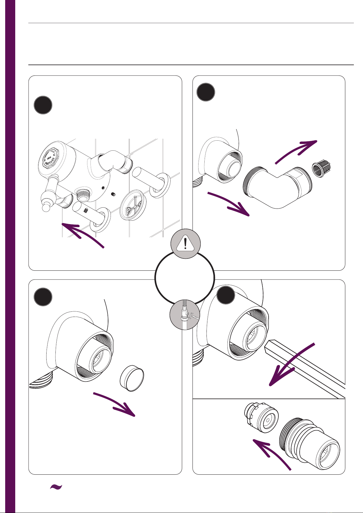
MAINTENANCE
Servicing the Elbows:
IMPORTANT
Isolate the
water supply
before starting!
2
1
34
Disconnect your shower kit.
Undo the compression nuts and grub
screws at the bottom of the shower
valve to remove from the wall.
Remove the lters from both elbows
and set aside. Unscrew the elbows
completely from the shower valve.
If installed, use a pair of long-nosed
pliers to remove any ow regulators
tted. Set aside.
Remove the
check valves
from the
back of each
housing.
Use a 10mm hex key
to remove the check
valve housing from
each inlet.
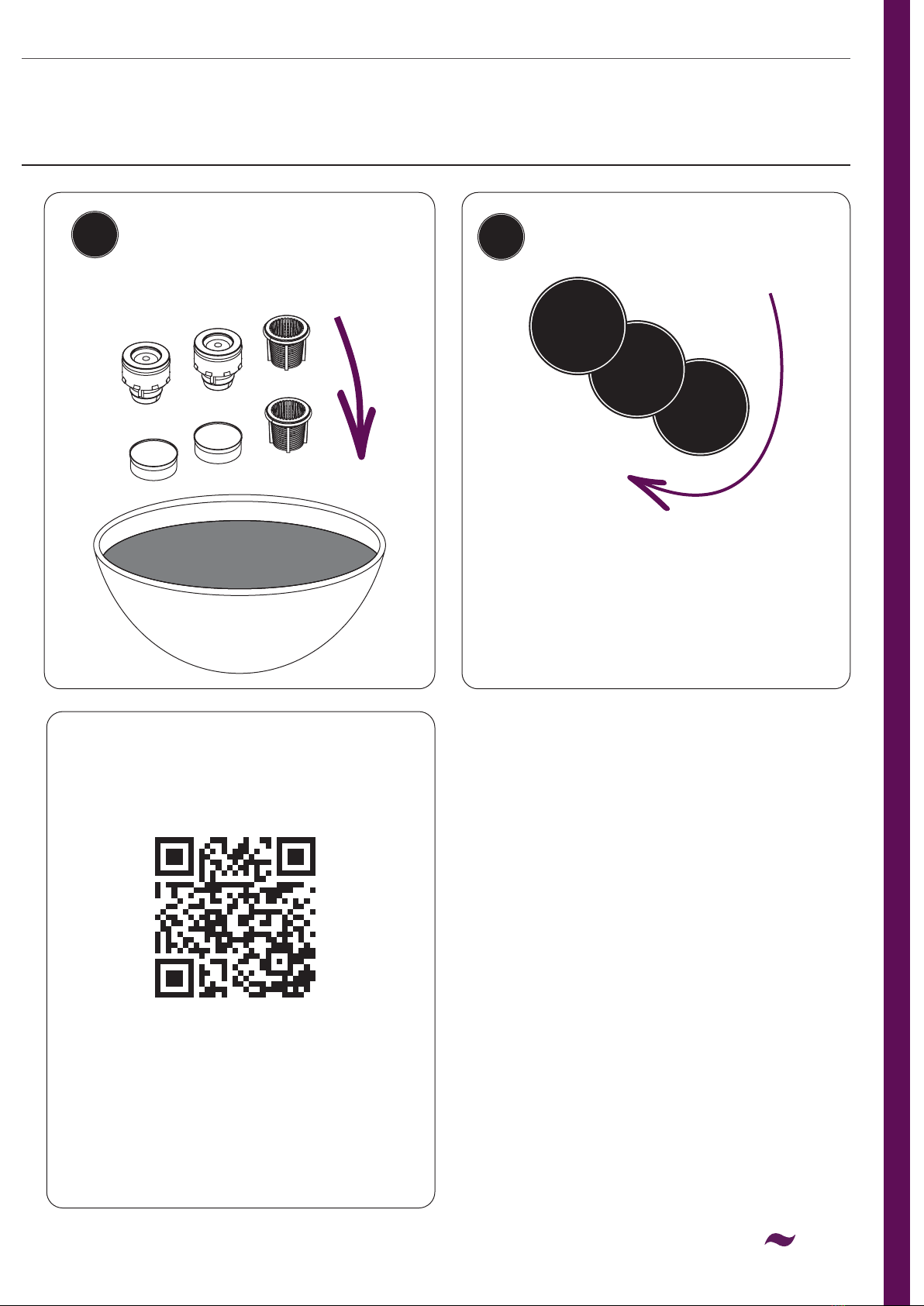
17
MAINTENANCE
56
Check all components for
damage and replace if necessary.
Rinse thoroughly in clean water
to remove any debris.
Reverse the steps to re-t the
elbows and secure the shower
to the wall. Test all joints and
connections for any leaks.
3
2
1
Spare Parts
Please visit
www.heritagebathrooms.com
or scan the QR Code and search
for your product code to replace any
available spare parts for your tap.
18
TROUBLESHOOTING
Symptom Cause Remedy
No ow or low
ow rate
Partially closed isolation valve. Open isolation valve.
Instantaneous water heater cycles on and off
as ow rate or pressure is too low.
Increase water ow rate or
pressure through system.
Head of water is below the
minimum distance required.
Refer to the specication for the
minimum distance required.
Are the water supply pressures balanced?
If pressures are unbalanced, a pressure
reducing valve should be used for
optimum performance.
Hot or cold water being drawn off elsewhere
causing pressure changes or instantaneous
boiler temperature changes.
Do not use other water outlets when
using the shower.
Airlock or partial blockage in the
supply pipework.
Flush through pipework and lters to ensure
removal of debris and any airlocks.
Hot/Cold water supply has failed Check the hot and cold feeds. The shower
will not work if either fails.
Outlet Water
Temperature
too Hot/Cold
Maximum Water Temperature
needs adjusting.
Refer to the Temperature Setting section to
set your desired maximum temperature.
Filter/pipe blockage Flush through pipework and lters to ensure
removal of debris and any airlocks.
Installation conditions outside
operating parameters.
Refer to the specication for the
minimum distance required.
Hot water temperature is less than 10°C
above the required blend temperature
Adjust hot water temperature or wait
for water to reheat if a stored water
system is used.
Instantaneous water not igniting because
the water ow rate is too low.
Increase water ow rate through the system.
Refer to the Maintenance section to clean/
check the cartridge and lters for any damage.
Contact your boiler manufacturer.
Instantaneous water not igniting because the
water pressure is too low.
Refer to the specication for system
requirements. Increase water pressure
through the system.
Contact your boiler manufacturer.
Only hot/cold
water from
Shower Valve
Inlet water supplies are reversed.
Check the water inlet connections are the
correct way around: Hot on the left, Cold on
the right when viewed from the front. Rework
pipework as necessary.
Filter/pipe blockage Flush through pipework and lters to ensure
removal of debris and any airlocks.
Water
dripping from
shower
This is normal for a short time after
using the shower.
This is caused by residual water tension,
the build up of water in the shower.
If water continues to drip,
possibly due to the cartridge
Remove cartridge and clean, refer to
'Maintenance' section before starting
any maintenance.
Shower does
not turn on
Closed isolation valve. Open isolation valve.
Mains water supply turned off. Turn on mains water supply.

19
Heritage products are made from premium materials, with hand polishing, PVD, EPD and
electroplated nishes.
Your product should be regularly cleaned with warm water, a mild pH-neutral liquid soap, and
polished with a soft cloth. Any residues from soap, toiletries etc. should be rinsed off straight
after use.
Household bleaches and cleaners contain harsh chemicals and may damage the surface nish.
Avoid using abrasive cloths, scouring pads, scrub sponges, steel wool or anything similar.
Some surfaces such as nickel and pewter may be affected by the dye found in some cloths, so it is
also important to avoid leaving cloths on surfaces.
The condence we have in the quality of our products and services enables us to offer a free
peace-of-mind product guarantee from 2 years up to a lifetime guarantee against any manufacturing
faults, with proof of purchase. In addition, our attentive customer service team are available to
help solve any problems which may arise quickly and effectively so you can enjoy your bathroom.
To see the specic guarantee for this product, scan the QR Code
or visit the following URL:
https://www.heritagebathrooms.com/service-centre/guarantee
In the unlikely event that you encounter a problem with your Heritage product, you must, in the
rst instance, contact the retailer you purchased it from. They will advise as to whether it is due
to a manufacturing fault or an installation fault. If the problem is due to a manufacturing fault, they
will contact us to arrange a supply of a replacement product as soon as possible. To speak to a
Heritage customer service advisor, please contact our technical helpline on 0330 026 8503.
NEED HELP?
GUARANTEE
CARING FOR YOUR PRODUCT

We love to see how Heritage products are used so please keep in
touch and share pictures of your new bathroom with us.
If you have any queries, our dedicated customer service teams and products experts are available
to help.
Email us enquire@heritagebathrooms.com Call us 0330 026 8503 Website www.heritagebathrooms.com
@heritagebathrooms
UK: Heritage Bathrooms, Pooley Hall Drive, Birch Coppice Business Park, Dordon, Tamworth B78 1SG
EU: Masco Europe S.à.r.l., 14 Rue Strachen, 6933 Mensdorf, Luxembourg.
D4
This manual suits for next models
2
Table of contents
Other Heritage Bathroom Fixture manuals

Popular Bathroom Fixture manuals by other brands

Kohler
Kohler Mira Sport Max J03G Installation and user guide

Moen
Moen 186117 Series installation guide

Hans Grohe
Hans Grohe Raindance Showerpipe 27235000 Instructions for use/assembly instructions

Signature Hardware
Signature Hardware ROUND SWIVEL BODY SPRAY 948942 Install

fine fixtures
fine fixtures AC3TH installation manual

LIXIL
LIXIL HP50 Series quick start guide


