Heritage HM-560B Quick guide
Sentry E-Call
Model HM-560B
Photoelectric
Smoke Detector
Issue 1, March 2005430-560B 0305 ©Heritage MedCall, Inc.
Heritage MedCall
Page1 Issue1,March2005
Heritage Medcall Sentry Emergency Call System
Model 560B Smoke Detector
Installation and Service Instructions
460-560B 0305 ©HeritageMedCall,Inc.
PRINCIPLEOFOPERATION
TheModel HM-560Smoke Detectoris aconventional
4-wire12 VDC photoelectric smoke detector. This
technologyis superior in reliability andperformance to
less expensive ionization type smoke detectors.A
highintensity infrared light emitting diode(LED) light
source is pulsed in a sensing chamber that is de-
signed for optimum smoke entry. The light source
LEDand aphoto-diode sensor arepositioned inthe
chamber at angles to each other so that when no
smoke is in the chamber, the sensor sees virtually no
light.
Light scattered by smoke particles in the chamber is
sensed by the photo-diode. When the light reaching
thephoto-diodereaches apredetermined level, the
detector will sound an alarm. Once the smoke has
been cleared from the unit, it is reset by pushing the
Check-Inbutton on the apartment HostPanel.
Becausesmoke may have to travel some distance
from the fire source to the detector, it is important that
the photoelectric detector responds best to both open
flameand smoldering fires.
TheHM-560B SmokeDetector includesautomatic
sensitivity testing. Once daily and upon power-up the
detector performs a full diagnostic test that includes a
dynamic test of the sensing chamber and internal
electronics. This meets NFPA72 field sensitivity
testingrequirements withoutthe needfor external
meters.
Thedetector also contains an integralpiezoelectric
hornwhich produces an interrupted 85dBaTemporal
3 tone.
WHERETOLOCATE
Thesmoke alarm should be installed in accordance
withNational Fire ProtectionAssociation(NFPA)
Standard 72. Excerpts follow:
A-8-1.2.1a Where to Locate the Required Smoke
Alarms in Existing Construction
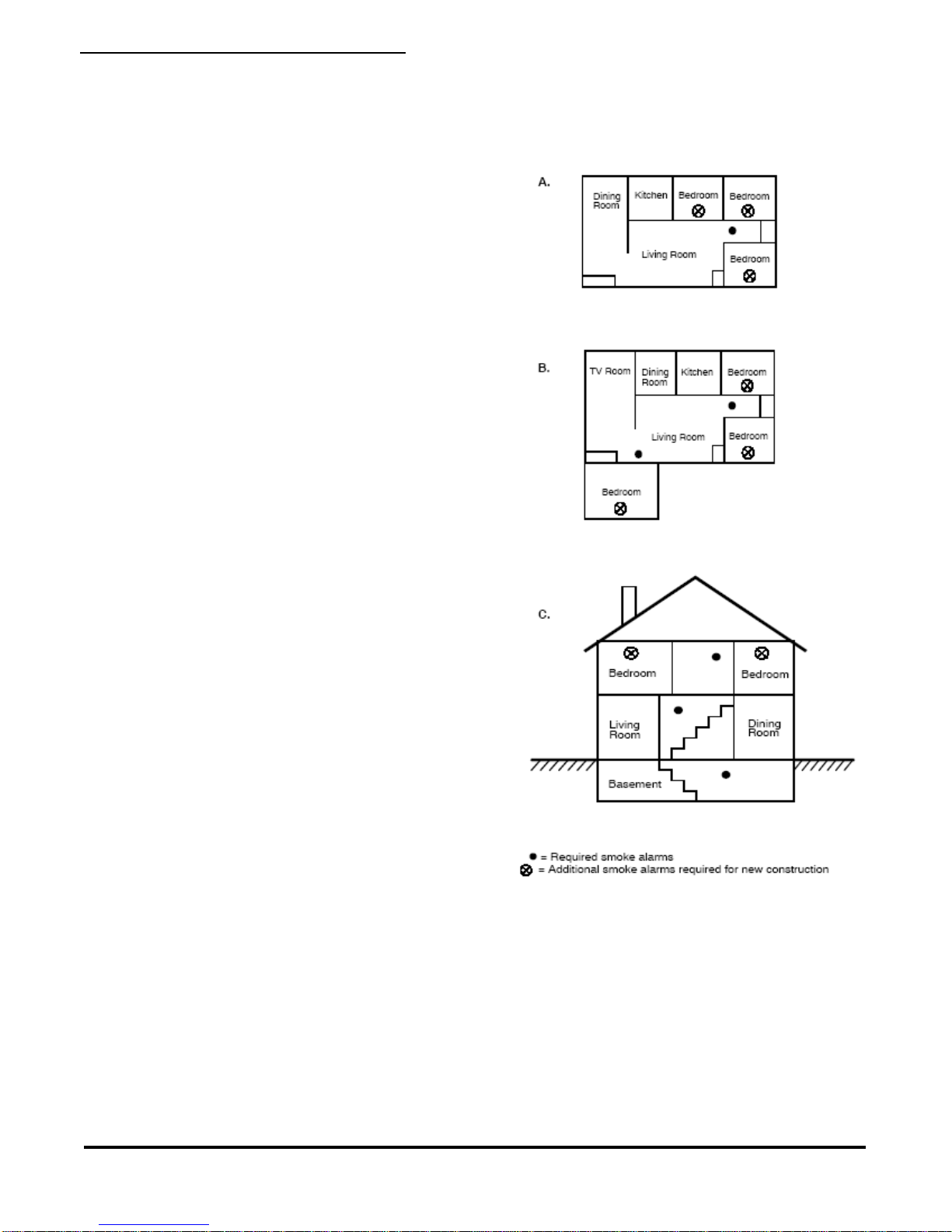
Themajor threat fromfire in afamily living unitoccurs
atnight when everyone is asleep. Theprincipal threat
to persons in sleeping areas comes from fires in the
remainderof theunit. Therefore, a smoke detector(s)
isbest located between the bedroom areas and the
rest of the unit. In units with only one bedroom area
onone floor,the smoke detector(s) should be located
as shown in Figure 1A.
Infamily livingunits withmore than one bedroom area
orwith bedroomson more than one floor,morethan
one smoke detector is required, as shown in Figure
1B.
In addition to smoke alarms outside of the sleeping
areas, the installation of a smoke alarm on each
additional story of the family living unit, including the
basement,is required. These installations are shown
inFigure 1C. The livingarea smoke alarm should be
installed in the living room or near the stairway to the
FIGURE1DETECTORLOCATION

Page2
Heritage Medcall Sentry Emergency Call System
Model 560B Smoke Detector
Installation and Service Instructions
430-560B 0305 ©HeritageMedCall,Inc. Issue1,March2005
upperlevel, or in both locations. The basement
smoke alarm should be installed in close proximity to
thestairway leading to the floor above. Where
installedon an open-joistedceiling, the alarm should
be placed on the bottom of the joists. The alarm
shouldbe positioned relative to the stairway to
intercept smoke coming from a fire in the basement
before the smoke enters the stairway.
Where to Locate the Required Smoke Alarms in
ExistingConstruction
All of the smoke alarms specified for existing con-
struction are required and, in addition, a smoke alarm
isrequired ineach bedroom.
Are More Smoke Alarms Desirable?
Therequired numberof smokealarms mightnot
providereliableearly warningprotectionfor those
areasseparated bya door fromthe areasprotected
by the required smoke alarms. For this reason, it is
recommendedthat the (designer/installer)consider
theuse of additional smoke alarms for those areas for
increasedprotection. The additionalareas include the
basement,bedrooms, dining room, furnace room,
utility room, and hallways not protected by the
requiredsmoke alarms. The installation of smoke
alarms in kitchens, attics (finished or unfinished), or
garagesis not normallyrecommended, as these
locations occasionally experience conditions that can
resultin improper operation.
IMPORTANT!
REGULATIONSPERTAININGTOSMOKE
DETECTORINSTALLATIONSVARY FROM STATE
TO STATE. FOR MORE INFORMATION, CONTACT
YOURLOCALFIREDEPARTMENTOR LOCAL
AUTHORITYHAVINGJURISDICTION.
In addition to NFPA72, use the following location
guidelinesto optimizeperformance andreduce the
chanceof false alarms.
Locate ceiling mounted smoke detectors in the center
of a room or hallway at least 4 inches from any walls
orpartitions.
Locate wall mounted smoke detectors so the top of
the alarm is 4 to 12 inches below the ceiling.
Whenmore than onedetector is required,spacing of
30 feet may be used as a guide on smooth ceilings.
Otherspacing may be used dependingon ceiling
height,high airmovement, andother conditions or
responserequirements.
Locatein asuitable environment:
-Temperaturebetween32°F(0°C) and 100°F(38°C)
-Humiditybetween0 and95% non-condensing
Locateaway fromair conditioners, heating registers
andany otherventilating sourcethat may interfere
withsmoke entering thedetector.Locate away from
kitchens,wood stoves,garages, furnacesand
bathrooms.
Mountsmoke detectors ona firm permanent surface,
typically a stud or metal runner.
Additionalinformation onHousehold FireWarning is
availableat nominalcost from:The NationalFire
ProtectionAssociation, 1 Batterymarch Park, Quincy,
MA02169-7471orwww.nfpa.org. Requestthelatest
StandardNo. NFPA72.
FIGURE2DETECTOR PLACEMENT
PENDANTRECEIVEROPTION
TheModel HM-547 PendantReceiver issometimes
used in apartment installations to receive a call signal
froma handheldwireless pendant.The locationof a
smokedetector towards the center ofthe living area
within an apartment makes a good location to install

Page3 Issue1,March2005
Heritage Medcall Sentry Emergency Call System
Model 560B Smoke Detector
Installation and Service Instructions
460-560B 0305 ©HeritageMedCall,Inc.
thereceiver. Thereceiver’s 3/4" thickenclosure is
designed to fit in the smoke detector electrical box.
Often a facility will purchase a few sets of pendants &
receivers to use on a special basis for residents that
mightbe recuperating fromsurgery. With the
possibility of future use, always install 2 or 4 extra
conductors to the smoke detector wiring.
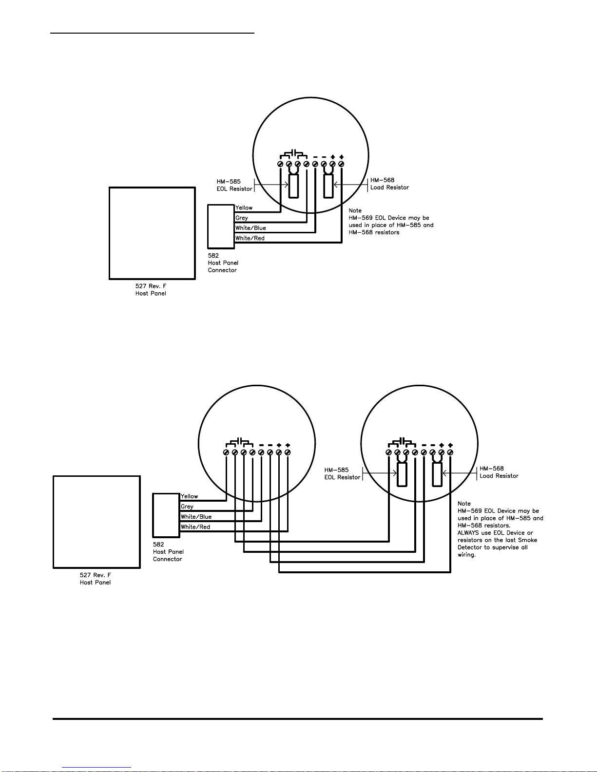
SUPERVISION
Powerwiring in four-wire systems isrequired by NFPA
72to be supervised. Smoke detectors aresupervised
bythe apartment host panel andthe console. Supervi-
sionis achievedby using both the End-Of-Line(EOL)
resistor(P/N HM-585) anda Smoke Load resistor
(P/NHM-568) or byusing theEnd-of-Line Device(HM-
569).This typeof supervisionrequires that multiple
smoke detectors are wired in a daisy chain, from the
host panel to the last detector which includes the
EOL and Smoke Load or EOL Device. When the host
panel is located in the apartment center, the wire
must go to one detector then back towards the host
panel and on to the last detector.
NOTE: Wiring must be installed so when a
detector is disconnected for any reason, the end-
of-line resistor or device must become
disconnected.
A break in the detector power circuit or contact circuit
will cause a trouble annunciation at the Sentry
console.
WIREREQUIREMENTS
The Sentry smoke detector can be installed in many
differentarrangements to meetmost system
requirements.The wiringdiagrams illustrate the
typical installation methods and shows the
recommendedminimum numberof conductorsto use.
Sentryrecommends to always have anadditional 2 or
4conductors as sparefor future options.
HeritageMedCallrecommends thefollowing wireor
equivalentfor installationof the Sentry smoke
detectors:
6 conductor: West Penn Wire (WPW) # 252
8 conductor: WPW # 253
DUST PROTECTION
System installers should be directed to place the
plastic dust cover that comes in the smoke detector
cartonover the installed detector. This simple step
willprotect the sensing chamber and screens from
theusual dust buildup during constructionand
painting.
FIGURE 3 PLUG-IN TERMINAL BLOCK
FIGURE4 DETECTORMOUNTING
INSTALLATION
Thedetectors mountto standardsingle-gang electri-
calboxes, four-inchoctagonal orfour-inch square
electricalboxes, or onWIREMOLD No. 5739 fixture
boxes. The detectors may also be mounted directly to
walls or ceilings where local codes/jurisdictions
permit.
1. Pull wire through the electrical box and connect to

Page4
Heritage Medcall Sentry Emergency Call System
Model 560B Smoke Detector
Installation and Service Instructions
430-560B 0305 ©HeritageMedCall,Inc. Issue1,March2005
theplug-in terminal block supplied, onewire per
terminal. See Figures 3 and 4.
2. Dress wiring neatly and snap the terminal block
into the back of the detector.
NOTE
The detector cover must be closed completely, to
support the circuit board, while installing the terminal
block.
3. Open the cover and mount the detector, using the
mountingholes provided.See Figure 4.
NOTE
Positiveair pressurefrom wireopenings, conduit,
mountingboxes, irregularmounting surfaces,or
plenumscausing air movementthrough andaway
fromthe detectormay preventproper operation. Seal
allopenings causingunwanted airflow using UL
Listedexpanding foamor Duxseal.
4.Remove the red plastic dust cover from the detec-
tor.The detectorsare shipped witha dust coverfor
protectionon construction siteswith dusty environ-
ments.
ENERGIZINGTHESMOKE ALARM
During system installation the smoke detectors can
be preliminarily tested by applying DC power to the
apartment’shost panelwithout console operation.
Normal operation is indicated by a visible LED on the
face of the unit that will flash approximately once
every9 seconds.
INSTALLATION TEST
After all connections are complete and the wiring is
checkedfor errors, apply power to the system. There
shouldbe no alarm. Ifan alarm isreported, determine
if a detector is latched in alarm or if there is a problem
withthe wiring.
SMOKETEST
The units should be tested in place annually using
oneof thefollowing methods:
A. Use Smoke! In a can® and follow the directions on
the can.
B. Hold a smoldering punk or cotton wick close to the
unit and gently direct the smoke into the smoke entry
openings for 20 seconds or until an alarm is indicated.
Be sure to properly extinguish the smoke source
after testing! This is a go/no go test and is not a
reliable indication of detector sensitivity. If it is
successful, the LED will remain lit.
Toreset the detector,operate theCheck-In button on
the unit host panel. The control unit alarm and all
auxiliaryfunctions shouldbe verifiedfor acomplete
test of each detector.
HEAT TEST
TheHM-560B SmokeDetectorssample forheat every
3 seconds. Test heat sensors by using a hot air gun.
Aim the gun at the heat sensor from 6-10 inches (15-
25cm) away. The detector should go into alarm in less
than 30 seconds.
SENSITIVITY TEST
1. Hold the magnet on the hinge side of the unit for
morethan one second(see Figure 7). The LED will
flash 1 to 9 times.
2. Count the number of LED flashes, then use the
following table to determine if any action is necessary.
Flashes
0-1 Indication:Unserviceablehardware fault.
Action: Reset and rerun sensitivity test. If the
errorpersists, replace unit.
2-3 Indication: Unit isbecoming insensitive.
Action: Clean and reset the unit. Rerun
sensitivity test. If the error persists, replace
the unit.
4-7 Indication: Unit is within normal sensitivity
range.
Action: N/A
8-9 Indication: Unit is becoming toosensitive.
Action: Verify the optical chamber is snapped
down securely. Clean the unitand replace the
opticalchamber.
After the sequence of flashes, if the sensitivity is
within limits and all other tests pass, the unit goes
into alarm until reset by the host panel. If the sensitiv-
ity is not within limits, or an unserviceable hardware
fault is detected, the alarm LED will continue to flash
once per second until the unit is reset by the host
panel.

Page5 Issue1,March2005
Heritage Medcall Sentry Emergency Call System
Model 560B Smoke Detector
Installation and Service Instructions
460-560B 0305 ©HeritageMedCall,Inc.
FIGURE 5 SENSITIVITY TESTING
MAINTENANCE
Thesmoke detectorsare designed foreasy field
serviceand maintenance.If adetector driftsbeyond
itsapproved sensitivityrangefor more than 24 hours,
or fails internal diagnostic tests, the unit automatically
indicates trouble by flashing its LED every second.
Thismeets field sensitivity testing requirements
withoutthe need for external meters.
NOTE
Connect to a power supply that will not automatically
reset. Since the self-diagnostics only indicate trouble
after27 hours, if the power supply automatically
resetstheself-diagnostic indication willnever be
signaled (the smoke detector will still signal alarm
correctly).
Inaccordance with NFPA72, smoke detector sensitiv-
ity should be checked within one year after installa-
tionand everyalternate yearthereafter, in commercial
installations, or every three years in residential sites.
See Sensitivity Test.
Thedetector’s replaceableoptical blockchamber
unsnapsfor easy fieldcleaning andservice. Whenever
the status LED indicates cleaning is necessary, follow
these steps:
1.Open thedetector cover,unsnapand throw away
the optical block chamber. See Figure 6.
2.Thoroughly blow off the opticalbase and snapa
new optical block chamber (part #211) back in place.
NOTE
Be sure the new optical block chamber is seated all
theway down.
3.Close the detector cover andverify sensitivity. See
Sensitivity Test.
FIGURE6 DETECTOR MAINTENANCE
OPERATION
Smokedetectors arepowered, monitored,and
supervisedby theapartment host panel.The host
panel is the master call panel for each apartment.
The host panel monitors the detector’s contacts and
will send an alarm to the console when the detector’s
relay is energized greater than 20 seconds. This
delay is built-in to the host panels’ program to provide
a“verification” feature oftenspecified oninstallations.
Host panels are polled by the console every 3.5
seconds, and the host panel must report the smoke
alarmon two consecutive pollcycles before the
console will announce the smoke condition.
Thesedelays areintentional and will greatly reduce
nuisancealarms; howeverwhen testing, a delay ofup
to 49 seconds can be realized before the alarm is
announcedat theconsole.
TANDEMOPERATION-MULTIPLEDETECTORS
When more than one smoke detector is installed in
an apartment, they are connected to all sound when
any one detector senses smoke. This connection
methodis referredto as“tandem” operation.

Page6
Heritage Medcall Sentry Emergency Call System
Model 560B Smoke Detector
Installation and Service Instructions
430-560B 0305 ©HeritageMedCall,Inc. Issue1,March2005
SMOKEDETECTOR TROUBLE
A detector malfunction is displayed on the console
screenas “Smoke Trouble”. The hostpanel will send
this trouble signal when the circuit to the detector’s
End-Of-Lineresistor orSmoke Loadresistor opens.
When the console receives and displays a smoke
detector trouble signal, note that the host panel in
that apartment is functioning correctly.
Whenutilizing the Model HM-569 EOLdevice the
module electrically connects a 3300 ohm EOL
resistor only when the detector is powered by at least
9 volts. This EOL device will enable the console to
sense Smoke Detector Trouble if voltage to the last
detector is lost or the EOL device is disconnected.
To operate a host panel with a smoke detector and
NOT display Smoke Detector Trouble on the
console screen, the smoke detector must:
1.Have anEOL resistor(HM-568) 3.3K
resistor across the alarm contacts.
2.Have a Smoke Load Resistor(HM-585)
1.2K resistor across the power terminals.
3. Use a model HM-569 EOL device in place
of1 and 2above.
TheModel HM-560BPhotoelectric smokedetector
normally draws 70uA DC. It operates at 9 to 16 volts
and is powered by the host panel. When the horn is
soundingthe current draw is 10mA. Multiple detector
installationswill have multiplesof these currents
dependingon thenumber of detectors.
TROUBLESHOOTING
When Smoke Trouble shows on the screen, the
following steps can be taken to quickly diagnose the
cause.
NOTE: Thisprocedure assumes the host panel is
functioningproperly and that the apartmentnumber
appears only as Smoke Trouble.
Goto the apartment. Checkfor detector operation as
described in SMOKE TEST at each detector. Normal
Operationwill soundthe hornafter applying smoke for
20 seconds.
NOTE: Whenmultiple smoke detectorsare present in
the apartment, any one detector’s alarm will cause
the others to sound.
If the smoke detector(s) do not sound, most likely the
DCpower hasbecome disconnected.Check wiring
andcheck forDC voltage atthe detector(s)DC Power
screw terminals. The DC voltage must be at least 10
volts.
Ifthe detector hasthe proper voltageand still does
not sound after the smoke test the detector is
malfunctioningand mustbe replaced.
Ifthe detector(s) operatenormally, the wiring to the
alarm contacts or the EOL device or resistor is most
likely the cause. Repair or replace the wiring, the EOL
deviceorresistor.
Removethe positivewire from the + DCPower
terminal.Check forDC voltage acrossthe alarm
contacts. It should read about 6 volts. Check all
detectors in the circuit. When the EOL device or
resistoris removed, the DC voltageacross the alarm
contacts should read 12 volts. If the reading is zero,
wiring to the host panel has an open on one of the
alarmsignal wires.Repair or replace the defective
wiring.
CONSTANT ALARM OR FALSE ALARM
Photoelectric smoke detectors can sometimes false
alarm if dirt or dust gets into the sensing chamber. If a
detector is in constant alarm, follow the procedures in
theMAINTENANCE section. If the alarmdoes not
clear,the detector will need replacement.
SPECIFICATIONS
Operatingtemperature ....32°Fto 100°F(0°C to38°C)
Operatinghumidity range ... 0 to95% non-condensing
Sounder specifications ..................... 85dB at 10 feet
Field wiring size .................................... 14-24 AWG
Self-diagnostic indication ..... typ. 27 hours after reset
Heat detector ........... fixed temp 135°F, 50 foot (15m)
spacingrate-of-rise 15°F/min> 105°F (8°C/min >
41°C)
Alarm contacts ............. 500mA @ 36VDC (resistive)
Dimensions .....6.1” (15.5cm) diameter x 1.9” (4.7cm)
deep
Weight .......................................... 8.8 oz. (0.25kg)
Color ............................................................. white
Page7 Issue1,March2005
Heritage Medcall Sentry Emergency Call System
Model 560B Smoke Detector
Installation and Service Instructions
460-560B 0305 ©HeritageMedCall,Inc.
FIGURE7 SINGLE SMOKE DETECTOR WIRING
FIGURE8 MULTIPLE SMOKE DETECTOR WIRING
Table of contents
Popular Smoke Alarm manuals by other brands


Edwards Signaling
Edwards Signaling SuperDuct TSD-SJ Installation sheet

Telenot
Telenot HD 1000 Operating and assembly instructions

ELOTEC
ELOTEC EO 120 Installation and maintenance instructions

First Alert
First Alert PR710-6BR user manual

Honeywell
Honeywell 5800COMBO Quick installation guide

Kidde
Kidde PI9000 Specification sheet


