HERKULES G202 User manual

Page 1 of 18
Part# 1002759-09
3/5/2012
Starts with S/N 60340
This manual contains important information concerning the
installation and operation of the gun washers listed above.
Read manual thoroughly and keep for future reference
INSTRUCTIONS
Herkules Equipment Corporation
2760 Ridgeway Court
Walled Lake, MI 48390-1662 USA
248-960-7100
800-444-4351
Fax 248 960-7109
Patents USA 7070167 4793369, 4960142, 5174317, 5193561, 5485860 Canada 1299468 & Patents Pending
website: www.herkules.us
Made in the USA
e-mail: info@herkules.us
Page 2 of 18
Warnings ……………………………………………………………………………………………………………………… 3-4
Assembly Instructions ……………………………………………………………………………………………………….. 5
Model Information ……………………………………………………………………………………………………………. 6
Installation
………………………………………………………………………………………………………………….. 6
Operation ……………………………………………………………………………………………………………………. 7-8
Preventive Maintenance ………………………………………………………………………………………………………. 8
Troubleshooting ……………………………………………………………………………………………………………… 9
Drawings with part lists: …………………………………………………………………………………………………… 10-18
Serial Number
Model Number
Purchase Date
Distributor
Table of Contents
Warning Symbol
Caution Symbol
CAUTION
WARNING
This symbol alerts you to the possibility of serious
injury or death if you do not follow the instructions. This symbol alerts you to the possibility of damage to
or destruction of equipment if you do not follow the
instructions.
This product has patent protection under
one or more of the following patent numbers:
7070167, 5485860, 5193561, 5174317
4960142, 4793369, 1299468
and Patents Pending
website: www.herkules.us
1002742
PATENT NUMBERS

Page 3 of 18
EQUIPMENT MISUSE HAZARD
Equipment misuse can cause the equipment to rupture, malfunction, or start unexpectedly
and result in serious injury.
•This equipment is for professional use only.
•Read all instruction manuals, tags, and labels before operating the equipment.
•Use the equipment only for its intended use.
•Do not alter or modify this equipment.
•Do not exceed the maximum working pressure of the lowest rated system component.
•Do not operate the gun washer at a pressure above the maximum working pressure rating of the
gun(s) being cleaned.
•Route the hoses away from traffic areas, sharp edges, moving parts, and hot surfaces.
•Do not use the hoses to pull the equipment.
•Do not move pressurized equipment.
•Use fluids or solvents that are compatible with the equipment wetted parts. Read the fluid and
solvent manufacturer's warnings.
•Comply with all applicable local, state and national fire, electrical and other safety regulation.
PRESSURIZED EQUIPMENT HAZARD
Spray from hose leaks, ruptured components, or from operating the gun washer with an open lid
can splash fluid in the eyes or on the skin and cause serious injury.
•A safety device has been installed to shut off the pump when the gun washer lid is opened.
Do not tamper with or alter this device.
•Open the gun washer lid slowly.
•Do not prop the gun washer lid open with an object or by any other means other than lid prop provided.
•Do not stop or deflect fluid leaks with your hand, body, glove, or rag.
•Tighten all fluid connections before operating the equipment.
•
Replace worn, damaged, or loose parts immediately.
WARNING

Page 4 of 18
FIRE AND EXPLOSION HAZARD
Improper grounding, poor air ventilation, open flames, or sparks can cause a hazardous condition
and result in fire or explosion and serious injury.
•Ground the equipment. See Installation for grounding procedure.
•Provide fresh air ventilation to avoid the build up of flammable fumes from the cleaning solution.
•Extinguish all open flames or pilot lights in the gun washer area.
•Disconnect all electrical equipment in the gun washer area.
•Keep the gun washer area free of debris, including cleaning solutions, rags, and gasoline.
•Do not turn on any light switch in the gun washer area while operating or if fumes are present.
•Do not smoke in the gun washer area.
•Do not operate a gasoline engine in the gun washer area.
•Follow the gun manufacturer's solvent and other cleaning recommendations.
•Use solvent with the highest possible flash point.
•If there is any static sparking while using the equipment,
stop operation immediately.
Identify and
correct the problem.
•Drain the cleaning solution into a proper storage container when gun washer(s) is not in use.
TOXIC FLUID HAZARD
Hazardous fluids or toxic fumes can cause serious injury or death if splashed in eyes or on the
skin, swallowed, or inhaled.
•Know the specific hazards of the fluid you are using. Read the fluid manufacturer's warnings.
•Store hazardous fluid in an approved container. Dispose of hazardous fluid according to all local, state
and national guidelines.
•Wear the appropriate protective clothing, gloves, eyewear and respirator.
•Pipe and dispose of the exhaust air safely. If diaphragm fails, the fluid may be exhausted along with
the air.
WARNING
Page 5 of 18
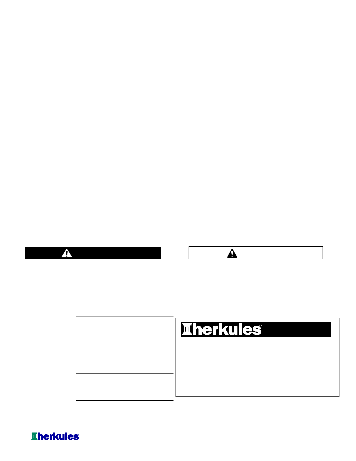
Connecting lid rod and actuator linkage
Attach the lid rod to the lid bracket using the 1/4" clevis pin and circular cotter pin supplied (see fig.1).
NOTE: The lid rod installs to the back side of the lid bracket.
Grounding the lid
Using an 1/8" allen wrench, remove the back right lid screw. Connect the ground wire (with an aluminum
terminal attached to both ends) from the pump to the lid screw and reconnect it to the tub (see fig.1).
Proceed to Installation on page 6.
STEP 3
Assembly
STEP 1
STEP 2
Lid screw
Ground wire
Lid rod
Lid bracket
fig.1 Cotter Pin
Clevis pin

Page 6 of 18
Model Information
Dimensions in./(mm)
A B C D
Two gun, two cup paint gun washer equipped with 46.25 22.6 25 21.25
diaphragm pump, filter-regulator, timer, manual brush (1175) (574) (635) (635)
clean for solvent or water based paints.
Installing the Gun Washer
1) Place gun washer on a level surface in a properly
ventilated paint mixing room or paint booth.
Grounding the Gun Washer
1) Connect the ground wire on the gun washer’s pump to a
true earth ground.
2) Ground all equipment used or located in the gun washer
area.
Connecting the Air Line
1) Install a 1/4 in. npt male coupler, that is compatible with
the quick disconnect of your air supply line, into the air
supply port of the filter/regulator located on the right rear
leg (see fig.2).
2) Connect air line with at least 75 psi to the coupler.
Filter/regulator is preset. Do not adjust.
Installation
Description
NOTE: Dimensions listed are overall measurements.
G202
Model
68
(31)
Weight
lbs/(kg)
A
B C
D
Air supply
port
fig.2
Page 7 of 18
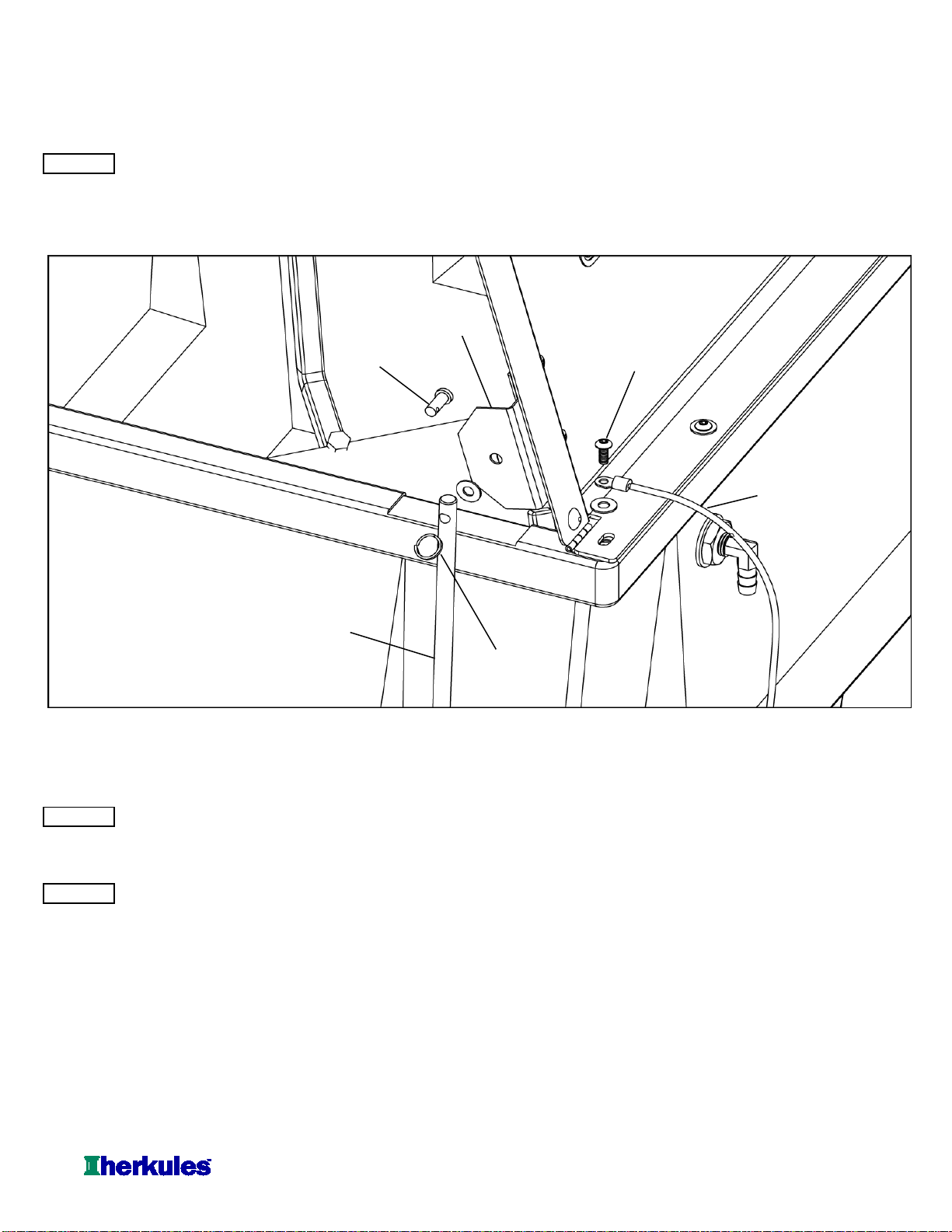
Operation
Filling the Gun Washer with Fluid Placing Equipment in the Gun Washer
1) Close ball valve located on the bottom of the tank. To clean guns not mentioned here, use the long or short
stem supports as needed (see fig.3). For questions or
2) Pour five gallons (18.9 liters) of high quality adapter kits contact your paint gun washer distributor.
cleaning solution into the tub. Unit is capable of
cleaning exclusively either solvent or water based paints. Siphon Feed Guns
Place the gun siphon tube on the short stem support.
Preparing the Equipment to be washed Gravity Feed Guns (HVLP)
1) Remove paint cup or paint line and the air line from the Place long stem support over one of the short stem
paint gun. supports. Place paint inlet of gun on long stem support.
Place the air cap assembly over the air inlet of the gun to
2) Drain excess paint from cup and gun. keep cleaning solution out.
3) Remove all gauges and regulators. Pressure Feed Guns
Place long stem support over one of the shorter stem
4) Lock the gun trigger in the open position by placing the supports. Place paint inlet of gun on long stem support.
trigger lock around the gun handle and trigger (see fig.3).
CAUTION Pots and Cups
All pressure gauges must be removed before placing the Place pots and/or cups on divider platform over front
equipment in the gun washer to avoid damaging the spray nozzles.
gauges.
fig.3 Trigger Lock
Long Stem Support
Short Stem Support
Gravity Feed
Gun (HVLP)
Siphon Feed Gun
Paint Cup
Pressure Feed Gun
Air Cap
Assembly
Page 8 of 18
Operation
Operating the Gun Washer Operating the Manual Brush
1) Make sure all wire trigger locks and other accessories 1) Make sure timer is turned off.
are inside the gun washer tub. 2) Prop open the lid with the Lid Prop and place equipment
2) If washing only one set of equipment, place empty cans over to be cleaned inside the gun washer.
the unused nozzles and/or stem supports to prevent
spray from hitting the underside of the gun washer lid. 3)
Hold brush so that the bristles point downward
inside the gun washer.
3) Close the gun washer lid. 4) Turn the lever on the valve assembly to the 'Brush
4) Turn the timer knob clockwise 90 degrees to start the gun Clean' position.
washer. The gun washer will run for 90 seconds. Turning
the timer knob less than 90 degrees will reduce the timing Note: DO NOT turn on timer. Brush operates without
cycle. Paint equipment will clean in 60 to 90 seconds. the timer controls.
5) If the lid is opened prior to the end of the timing cycle, the 5) To increase the flow through the brush, turn the
safety air cutoff switch will stop the gun washer. The knob of the flow control valve counterclockwise.
gun washer will start again when the lid is closed if time To decrease the flow through the brush, turn the
remains on the timer. knob of the flow control valve clockwise.
Note: Open the lid slowly to minimize vapor escape. 6) Clean parts as necessary, and when finished, remove lid
prop so lid will close.
6) Remove the equipment from the gun washer and wipe off
any remaining cleaning solution. 7) Turn the lever on the valve assembly to the 'Auto Clean'
position.
Note: The brush will continue supplying fluid until the
lever is returned to the 'Auto Clean' position.
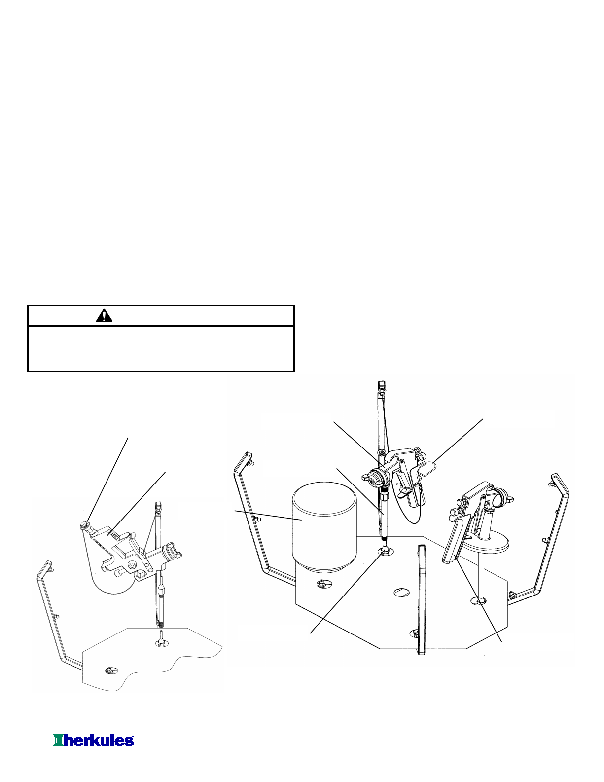
Preventive Maintenance
1) Drain excess paint from cup or pot before placing in gun
washer.
2) Drain paint sludge from gun washer tank weekly. Do this
after a weekend so that it has settled. Open ball valve
and drain until clear solution flows. Add cleaning solution
to fill 1" above intake filter.
3) Remove the filter bowl and check the filter inside the
regulator for excess buildup approx. every 6 months.
4) Change cleaning solution completely when objects being
cleaned become tacky to the touch.
5) Clean inside of tub and intake filter before filling with
cleaning solution.
Do not change the setting of the filter/regulator.This could
damage the filter/regulator or pump
CAUTION
Filter/Regulator
#T17M
Filter
#1001382 Filter Bowl

Page 9 of 18
Troubleshooting
Gun washer will not turn on. 1Make sure the air line is properly connected with at least 75 psi.
Air pressure is regulated at 75 psi.
2Make sure lid is fully closed. Make sure the lid rod actuator is making
full contact with the limit valve on the right rear leg.
3Check all air connections to ensure that there are no leaks.
4Make sure timer cam is engaging the limit valve on the right front leg.
5Make sure timer is on and functioning correctly.
6Make sure brush valve is turned to the 'Auto Clean' position for automatic
cleaning or 'Brush Clean' for manual brush cleaning.
Gun washer turns on but 1Make sure intake filter is not clogged (Clean or replace).
pumps slowly or not at all. 2Make sure the air line is properly connected with at least 75 psi.
Air pressure is regulated at 75 psi.
3Check all air connections to ensure that there are no leaks.
4Make sure there is 5 gallons of clean solution in the gun washer.
The cleaning solution should be an inch above the intake filter.
5Make sure lid is fully closed. Make sure the lid rod actuator is making
full contact with the limit valve on the right rear leg.
6Make sure manifold nozzles and stem supports are not clogged.
7Make sure brush valve is facing exactly in the desired direction.
Gun washer will not shut off 1Make sure timer cam is moving. If its not, slightly loosen the nuts
holding the limit valve on the right front leg of the stand. Reposition
valve and tighten nuts.
2Make sure limit valves located on the right front leg or right rear leg
of the stand are not stuck in closed position.
3Make sure brush valve is not turned to the 'Brush Clean' position.
4Make sure limit valve inside brush valve is not stuck in closed position.
Problem
Possible Solution
Page 10 of 18
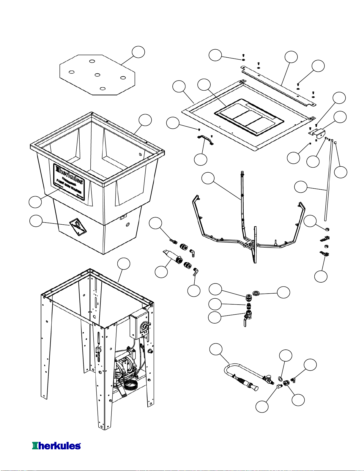
G202 Parts Layout
11
19
28
23
13
15
31
29
32
21
26
33
2
18
22
4
16
14
1
25
3
5
6
8
12
20
10
24
7
27
30
9
17

Page 11 of 18
Part # Description
16Ball Valve 1EA.
262 Reducing Nipple - Brass 1EA.
310737 Manual Brush Assembly 1EA.
411957 Actuator 2EA.
512490 Manifold Assembly 1EA.
612491 Filter for Pump Inlet 1EA.
712024 Lid Bracket 1EA.
812025 Lid Assembly 1EA.
912321 Lid Stop 1EA.
10 13893 Stand Assembly 1EA.
11 1000252 Cotter Pin 1EA.
12 1000651 Flammable Caution Sticker 1EA.
13 1000652 Clevis Pin 1EA.
14 1000967 Hose Barb 90° 3/8 x 1/4 NPT Brass 1EA.
15 1003048 Front Decal 1EA.
16 1001708 Lid Sticker 1EA.
17 1002546 Screw BHSC 10-24 x 1/2 4EA.
18 1002572 Actuator Rod 1EA.
19 1002643
Bulkhead with Nut 3/4" - Brass
1EA.
20 1002644 Bulkhead with Nut 1" - Brass 3EA.
21 1002654 Hose Barb 3/8 x 3/8 NPT - Brass 1EA.
22 1002650 Hose Barb 90° 3/8 x 3/8 NPT Brass 2EA.
23 1004740 Collar 3/4 OD x 3/8 ID 2EA.
24 002-131 Elbow Street 1/4 NPT Brass 1EA.
25 002-161 Washer Flat #10 USS Zinc 4EA.
26 005-103 Washer 3/4" - Nylon 1EA.
27 005-131 Screw PHM Phil 10-24 x 1/2 SS 2EA.
28 005-137 Nut Nylock 10-24 Zinc 2EA.
29 1-BLUE Tub 1EA.
30 10A Handle 1EA.
31 14C Rivet 3/16 x 1/2 Aluminum 2EA.
32 25D Divider 1EA.
33 85B Washer 1-1/2 x 1 - Nylon 1EA.
Note: For parts shown but not identified
refer to assembly layouts on pages 12-18
Note: Parts are shown for reference purposes only
and are not necessarily part of a Herkules assembly.
Quantity
G202 Parts Layout

Page 12 of 18
Part # Description
157 Hose Barb 3/8 x 1/4 NPT - Brass 1EA.
259 Hex Plug 1/8 NPT - Brass 2EA.
312509
Air Cap Assembly - Brass and Stainless
2EA.
41002321 Manifold Half - Stainless 2EA.
51002651 E-ring - Stainless 2EA.
6002-121A-6 Manifold Ground Wire 1EA.
7002-136S Manifold Bolt - Stainless 2EA.
8002-137 Manifold Block 1EA.
9002-192 Ground Wire Rivet 2EA.
10 22BA Trigger Lock Assembly 2EA.
11 53A Stem Support Male 2EA.
12 53B Stem Support Female 2EA.
13 54P1 Full jet Nozzle - White 12 EA.
14 64PE Manifold Hose 7IN.
15 C9A Nipple 4-1/2" - Brass 2EA.
Note: Parts are shown for reference purposes only
and are not necessarily part of a Herkules assembly.
G202 Manifold Layout
Quantity
12
4
13 1 14
11
3 10
8
6
9
15 5
7
2

Page 13 of 18
G202 Stand Assembly Layout
1
13
12
11
10
9
8
7
6
5
4
3
2
See Page 15-16 For Leg Assembly

Page 14 of 18
Part # Description
183 Bolt Hex Full 1/4-20 x 1 Zinc 2EA.
284 Nut Hex 1/4-20 Zinc 2EA.
385 Washer Lock 1/4 Zinc 6EA.
411958 Pump Bracket 1EA.
512517 Pump 1EA. See pg. 15
612663 Valve Assembly 1EA.
See pg. 17
71000116 Bolt Hex 1/4-20 x 5/8 Zinc 2EA.
81002378 Leg 4EA.
91002428 Frame 1EA.
10 1003597 Rivet 1/4 x 1/2 Aluminum 14 EA.
11 001-702 Bolt Hex 1/4-20 x 1/2 Zinc 2EA.
12 001-705 Washer Flat 1/4 USS Zinc 2EA.
13 008-244 Nut Acorn 1/4-20 Nickel 4EA.
Note: Parts are shown for reference purposes only
and are not necessarily part of a Herkules assembly.
For Leg Assembly with Regulator, see page 15-16 for Layout
For Leg Assembly with Timer, see page 15-16 for Layout
For Pump Assembly, see page 15-16 for Layout
For Valve Assembly, see page 17-18 for Layout
G202 Stand Assembly Layout
Quantity
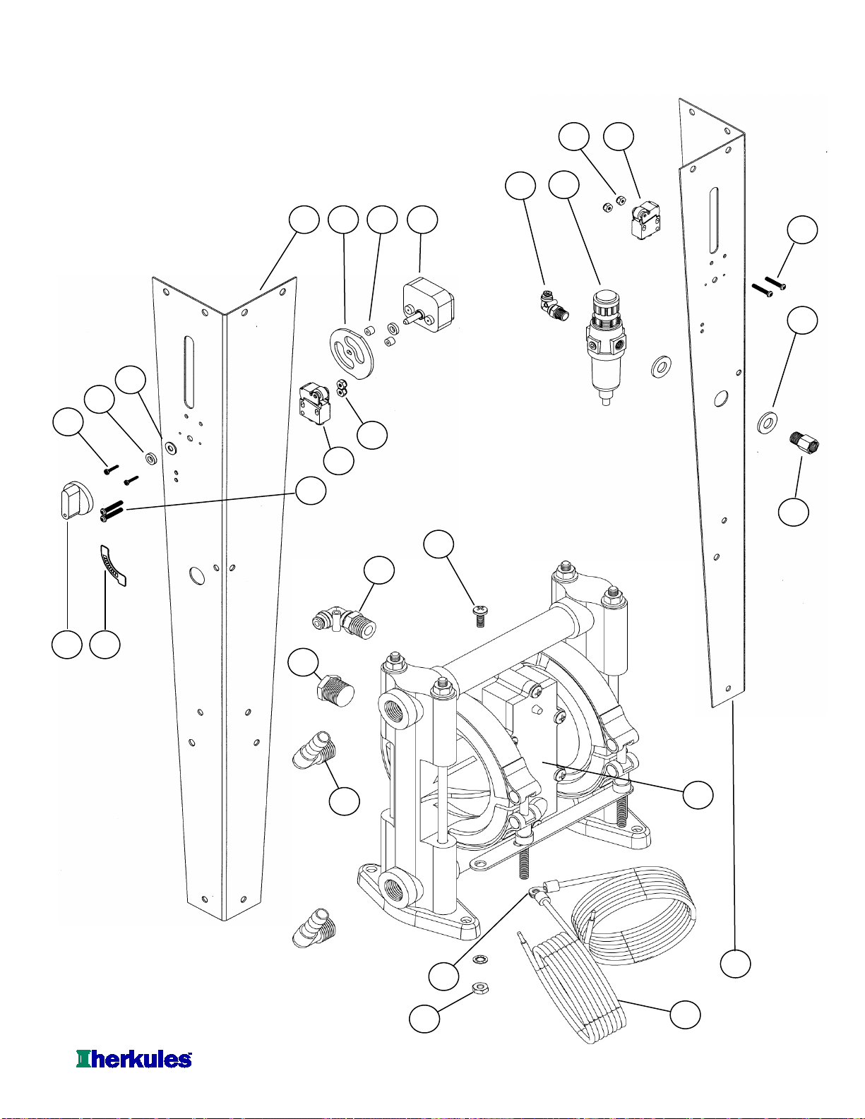
Page 15 of 18
G202 Pump and Legs Layout
10
14
4
22
23
11 15
4 19 1618
20
1
21
10
5
15
11
17
12
7
9
13
2
8
23
3
6

Page 16 of 18
Part # Description
167
Adaptor 1/4 NPT - Brass
1EA.
2338 Pump 1EA.
31001441 Muffler 3/8 NPT Zinc 1EA
41002378 Leg 2EA.
51002414 ON/OFF Sticker 1EA.
61002650 Hose Barb 90°3/8 x 3/8 NPT Brass 2EA
7002-106 Wire Terminal 3EA.
8002-120A-72 Ground Wire 2EA.
9002-161 Washer Flat #10 USS - Zinc 1EA.
10 002-171 Screw 8-32 x 1 - Black 4EA.
11 002-172 Nut Nylock 8-32 - Zinc 4EA.
12 005-131 Screw 10-24 x 1/2 - Stainless 1EA.
13 005-132 Nut Hex 10-24 - Stainless 1EA.
14 85D Washer Flat 1/2 - Zinc 2EA.
15 M1C Limit Valve - Gold 2EA.
16 M230-001A Timer 1EA.
17 M230-002 Knob for Timer 1EA.
18 M230-003 Cam For Timer 1EA.
19 M230-004 Spacer 1/4" Thick - Nylon 2EA.
20 M230-005 Spacer 1/8" Thick - Nylon 2EA.
21 M230-006 Timer Screw #4 x 5/8 2EA.
22 T17M Filter / Regulator 1EA.
23 T25 5/32 Hose Fitting 90° Swivel 2EA.
Note: Parts are shown for reference purposes only
and are not necessarily part of a Herkules assembly.
Quantity
G202 Pump and Legs Layout

Page 17 of 18
G202 Valve Layout
3
7
10
11
12
14
17
16
2
1
13
5
15
6
9
8
4

Page 18 of 18
Part # Description
184 Hex Nut 1/4-20 2EA.
285 Lock Washer 1/4 2EA.
311217 Mounting Bracket 1EA.
41000851 OR Valve 1EA.
51000907 Valve Actuator 1EA.
61002692 Valve Bracket 1EA.
71002761 Manual Brush Sticker 1EA.
81000967 Hose Barb 90°3/8 x 1/4 NPT Brass 3EA.
9002-160 Hex Nut 10-32 2EA.
10 002-171 Screw 8-32 x 1 3EA.
11 002-172 Nylock Nut 8-32 3EA.
12 002-173 Screw 10-32 x 5/8 2EA.
13 004-723 Set Screw 1EA.
14 59B Hex Plug 1/4 NPT 1EA.
15 83K Hex Bolt 1/4-20 x 3/4 2EA.
16 C26 Brush Valve 1EA.
17 M1C Limit Valve 1EA.
Note: Parts are shown for reference purposes only
and are not necessarily part of a Herkules assembly.
Quantity
G202 Valve Layout
Table of contents
Other HERKULES Power Tools manuals


