Herr Engineering HRR510 User manual
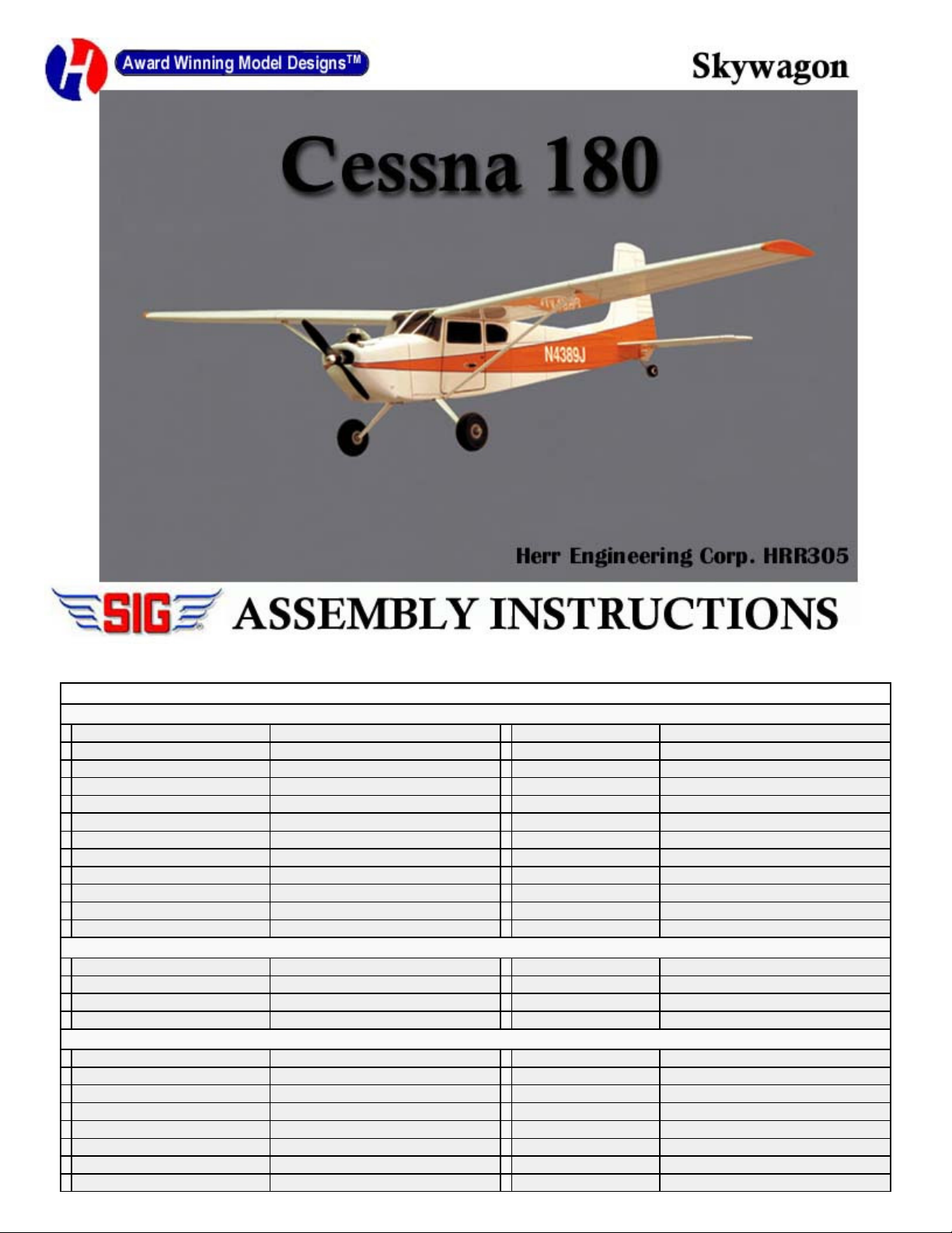
Your kit contains the following parts. Please check your kit for any missing or damaged parts before starting construction.
COMPLETE KIT PARTS LIST
Wood Bag:
1 LC-510-01 3/32x4x24 Laser Cut Balsa Sheet 1 LC-510-02 3/32x4x24 Laser Cut Balsa Sheet
1 LC-510-03 3/32x4x24 Laser Cut Balsa Sheet 1 LC-510-04 3/32x4x24 Laser Cut Balsa Sheet
1 LC-510-05 3/32x4x24 Laser Cut Balsa Sheet 1 LC-510-06 1/8x4x24 Laser Cut Balsa Sheet
1 LC-510-07 1/8x4x24 Laser Cut Balsa Sheet 1 LC-510-08 1/16x4x12 Laser Cut Balsa Sheet
1 LC-510-09 1/16x3x12 Laser Cut Birch Ply Sheet 1 LC-510-10 3mmx6x12 Laser Cut P plar Ply Sheet
1 LC-510-11 3mmx6x12 Laser Cut P plar Ply Sheet 2 Leading Edge 1/4 sq.x24 Balsa Strip
4 Leading Edge Stringers 1/8 sq.x24 Balsa Strip 2 Wing Tips 3/4 Balsa Triangle x4.5
8 Trailing Edge 1/16x1x14 Balsa Sheet 2 Trailing Edge 1/16x1x3.5 Balsa Sheet
4
Center Secti n Sheet 1/16x3x18 Balsa Sheet 2 C ntr l Surface Pushr d 1/16x18 Wire, Threaded One End
1 Thr ttle Pushr d 1/16x12 Wire, Threaded One End 1 Braces 3/32x3/16x8 Balsa Strip
4 Main Spars 1/8x1/4x24 Balsa Strip 4 Main Spars 1/8x1/4x13 Balsa Strip
2 Center Secti n Spars 1/4 sq.x3.5 Balsa Strip 2 Wing Strut 3/32x1/4x12 Balsa Strip
Misc. Parts Loose in Box:
1 Plan Sheet A 1 Plan Sheet B
1 Instructi n B k 1 Decal Sheet
2 Main Landing Gear 7.625 1 Plastic C wl
1 Clear Plastic .010x3x6
Hardware Bag:
1 Left Hand C ntr l H rn Small Nyl n C ntr l H rn 1 Right Hand C ntr l H rn Small Nyl n C ntr l H rn
4 H rn Screw 2-56x3/8 Machine Screw 1 Elevat r J iner 1/8x3 Birch D wel
8 Main Landing Gear & C wl Screw #2x3/8 Sheet Metal Screw 3 Nyl n Clevis Small Nyl n Clevis
1 N se Center Brace 3/16 sq.x3 Balsa 2 Wing B lt Plates (F-20) 3/16 Laser Cut Ply
2 Wing B lt Fillers 3/16 Tapered Balsa Wedge 1 Tail Wheel Wire 1/16 dia.x3 Music Wire
2 Wing D wels 3/16x3/4 Birch D wels 2 Wing B lts 10-32x1 Nyl n B lts
4 Strut Wires 1/16x1.25 Mild Steel Wire 1 Strut Tubes 1/8x2 Plastic Tube
2 Landing Gear Straps 1/4x3/4 Nyl n Strap 1 Tail Wheel Retainer Black Nyl n Retainer

.
The first thing that you need to do is to identify and mark the part numbers on the laser cut parts using the drawings on the
following pages as a guide.
It is possible that several of the laser cut parts may not be completely cut through. If this is the case you can free the part from
the sheet quickly using an X-acto knife.
NOTE: The slight discoloration on the edges of the laser cut parts may be removed by lightly sanding the edges with 400 grit
sandpaper.
.
Additional Items Required ( Not Included in Kit)
N te: These are parts that we have used and are familiar with. There are many ther brands available and y u may substitute ther items that
y u are m re c mf rtable with r have n hand.
1 Engine .049 t .061 Engine with thr ttle 1 Radi 3 Channel Radi with Mini serv s
3 Hinges Sig Easy Hinges #SH-710 3 Pushr d C nnect rs Sig #SH-736
2 C vering Material 2 R lls Ir n n c vering material 2 3/32 Wheel C llars Sig #SH-585
1 1/16 Wheel C llar Sig #SH-584 2 Main Wheels 2 Du-Br #200TL
1 Tail Wheel 3/4 Sullivan #351 T1 Tail Wheel 2 Wheel Bushings Make fr m K&S Brass Tube #127
1 M t r M unt Dave Br wn #0506 4 M t r M unt Screws 4-40 x 3/4 Machine Screws and Blind Nuts Sig #SH-111
1 Fuel Tank Sullivan 2 z. #SS-2 1 1/2-A Fuel Line Sig #SH-288
1 Pr peller Grish T rnad 6-3 Nyl n Pr peller
#GRIQ1050
General Note: Cover the plans with wax paper before assembling your model to prevent the parts from sticking to the plan.
Building the Tail Surfaces
1.
Join R-1 and R-2 together over the plan to make the fin. Join R-3 and R-4 together over the plan to make the rudder.
Temporarily hinge the rudder to the fin. Do not glue the hinges at this time. Bend the tail wheel wire to shape and glue it into
position into the bottom of the rudder.
2.
Join S-2 and S-3 together over the plan to make the elevators. Join the elevators using the 1/8 dowel. Use the plan and the
stabilizer as a guide. Trim the dowel as required to achieve the proper length.
.
3. Temporarily hinge the elevators to the stabilizer. Do not glue the hinges at this
time.
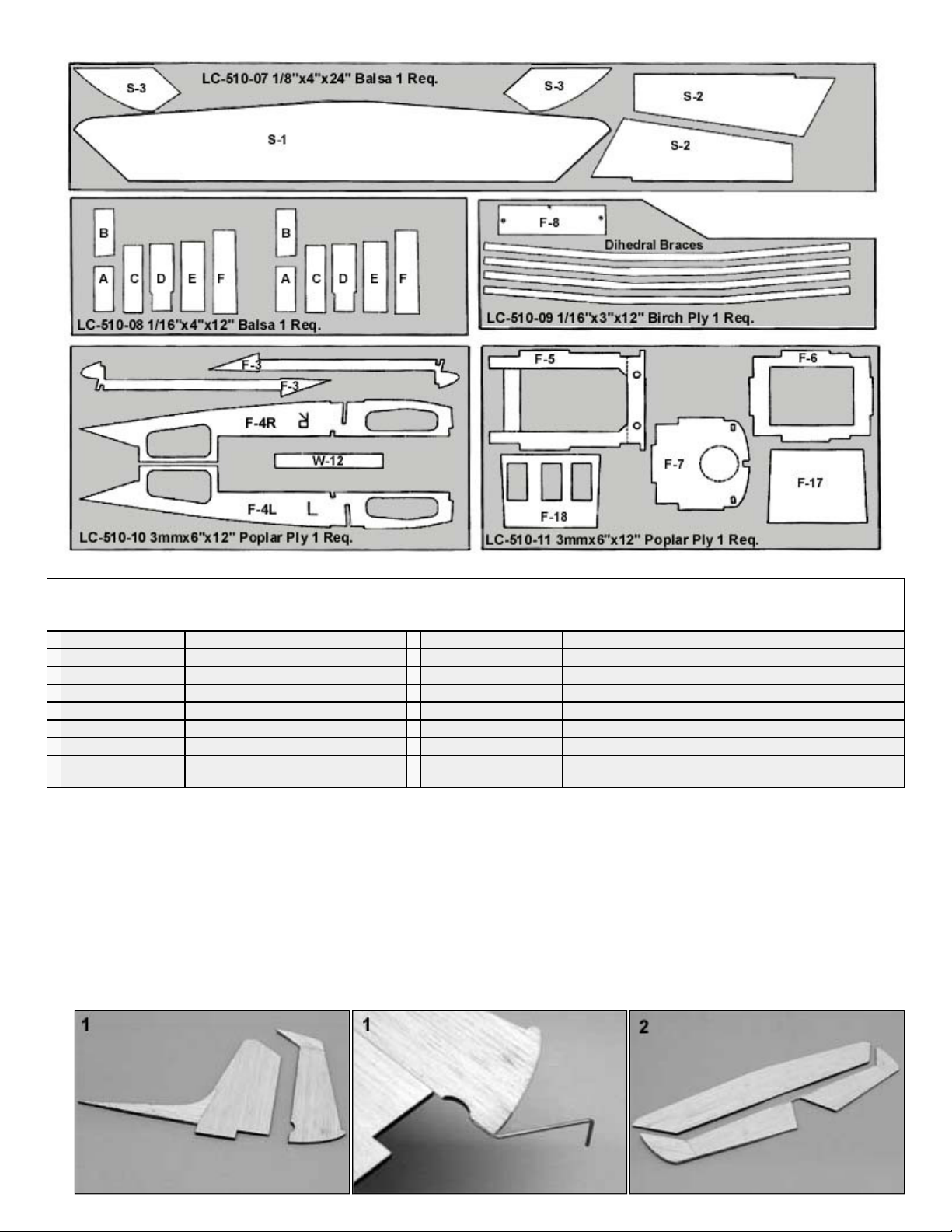
4.
Sand the tail surfaces smooth and round all of the edges except the bottom edge
of the fin.
Building the Fuselage
5.
Assemble the fuselages side by gluing
parts F-1 and F-2 together. Parts F-3
and F-4 are glued on the inside of the
fuselage. Parts F-
4 are marked with an L
or R for the left and right side. Be sure to
make a left and a right side.
6.
Cut part way through the top of former F-
5 at the dashed lines and gently crack it
at these locations to allow the top to
angle forward. Place the right fuselage
side on the building board and place
formers F-5 and F-6 into position. These
formers should be 90 degrees to the
Fuselage side. Glue the formers to the
fuselage side.
7.
Glue the left fuselage side into position
on the formers. The formers should also
be 90 degrees to this fuselage side.
8.
Gently squeeze the front of the fuselage
together and glue former F-7 into
position.
9.
Glue the plywood landing gear support
F-8 into position with the marking X at
the front and facing the toward the
outside of the fuselage.
10.
Remove the cross brace at the bottom of F-5 by cutting through the two dashed lines at the ends of the cross piece. Now
apply glue to the cracks in the top of former F
-
5.
11.
Glue two strips of 3/32 x 3/16 balsa strip across the front of former F-11 to brace it as shown on the plan. Also, glue one
strip to part F
-
10 as shown on the plan.

.
12. Gently squeeze the aft end of the
fuselage sides together and hold with
two clothes pins or a small clamp. Place
the formers F-11 and F-12 into position
and glue them to the fuselage sides.
Glue the aft end of the fuselage sides
together making sure that the joint is
straight and not leaning to the left or
right.
13.
Place part F-13 into position and glue it
to the center of formers F-6, F-11, and
F-12. Working from the front to the rear,
gently pinch the fuselage sides into
contact with F-13 and glue together.
14.
Place part F-14 into position and glue it
to the center of formers F-5, F-11, and
F-12. Now working from the front to the
rear, gently pinch the fuselage sides into
contact with F-
14 and glue together. The
front end should rest on and be glued to
F-8.
15.
Glue F-9 to the forward bottom of the
fuselage between F-7 and F-8.
16.
Mark and drill 1/16 holes in F-7 for the
motor mount. Attach the motor mount to
the firewall with 4-40 screws and blind
nuts. Now install the motor on the
mount. The back of the muffler should
be 1/32 away from F-7.
17.
Mark and drill 3/16 holes in the firewall for the throttle pushrod, fuel, and vent lines.
18.
Glue the F-19 fuel tank support into position. Now assemble the fuel tank and install into the model. Cut the motor mount
screws off flush with the back of F-7 so they do not interfere with the fuel tank.
19.
Fit part F-18 to the fuselage and glue
into position and glue both F-20s into
position at the top of the fuselage sides
and the front of F-6.
20.
Glue parts F-10, F-15 and F-16 into
position at the nose of the model. Now
glue the 3/16 sq. strip into position
between F-7 and F-16.

.
21.
Bend and test fit the throttle pushrod into position. Then remove from the fuselage until needed later.
22.
Glue one of the F-19 pieces into position. First, apply glue to the lower edge only and attach F-19 to the top edge of the
fuselage side. When the glue is dry, thoroughly wet F-19 with an ammonia based cleaner such as Sig’s Pure Magic
Airplane Cleaner and let it soak in for about 10 minutes.
23.
Now gently roll F-19 down into position
on formers F-7, F-15, and F-16. Hold in
this position until the moisture dries.
Mark F-19 at the centerline of the 3/16
sq. strip and trim with your hobby knife.
Now glue F-19 to F-7, F-15 and F-16.
24.
Now repeat this operation to install the
opposite F-19. Now set the fuselage
aside until needed later in construction.
Building the Wing
25.
Cut the lower 1/4 sq. main spar and the 1/16x1 trailing edge for the center section to length & pin into position on the plan.
26.
Glue the two lower plywood dihedral braces to the front and back of the lower spar.
27.
Cut and fit the forward and rear lower 1/16 sheet for the center section. The front piece is trimmed slightly long and is glued
to the front face of the forward dihedral brace. The rear piece is glued to the rear face of the rear dihedral brace and the 1
trailing edge.
28.
Glue ribs W-1 and W-2 into position on the lower spar and lower sheet. These ribs should be 90 degrees to the building
board. Glue the top 1/16 x 1 trailing edge into position.
29.
Glue the two tapered filler strips into
position between the top and bottom
trailing edges on either side of the center
W-1 rib.
30.
Glue part W-12 into position on top of
the lower 1/16 sheet and against the W-
1 and W-2 ribs.
.
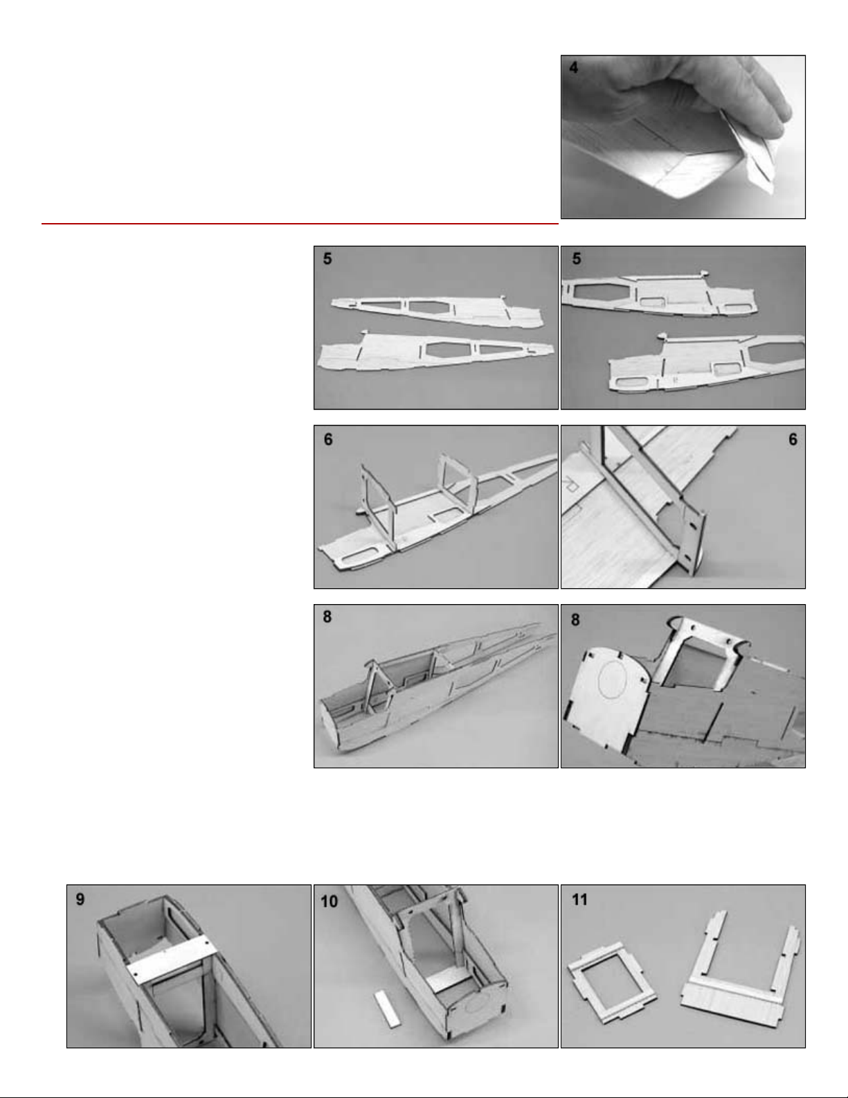
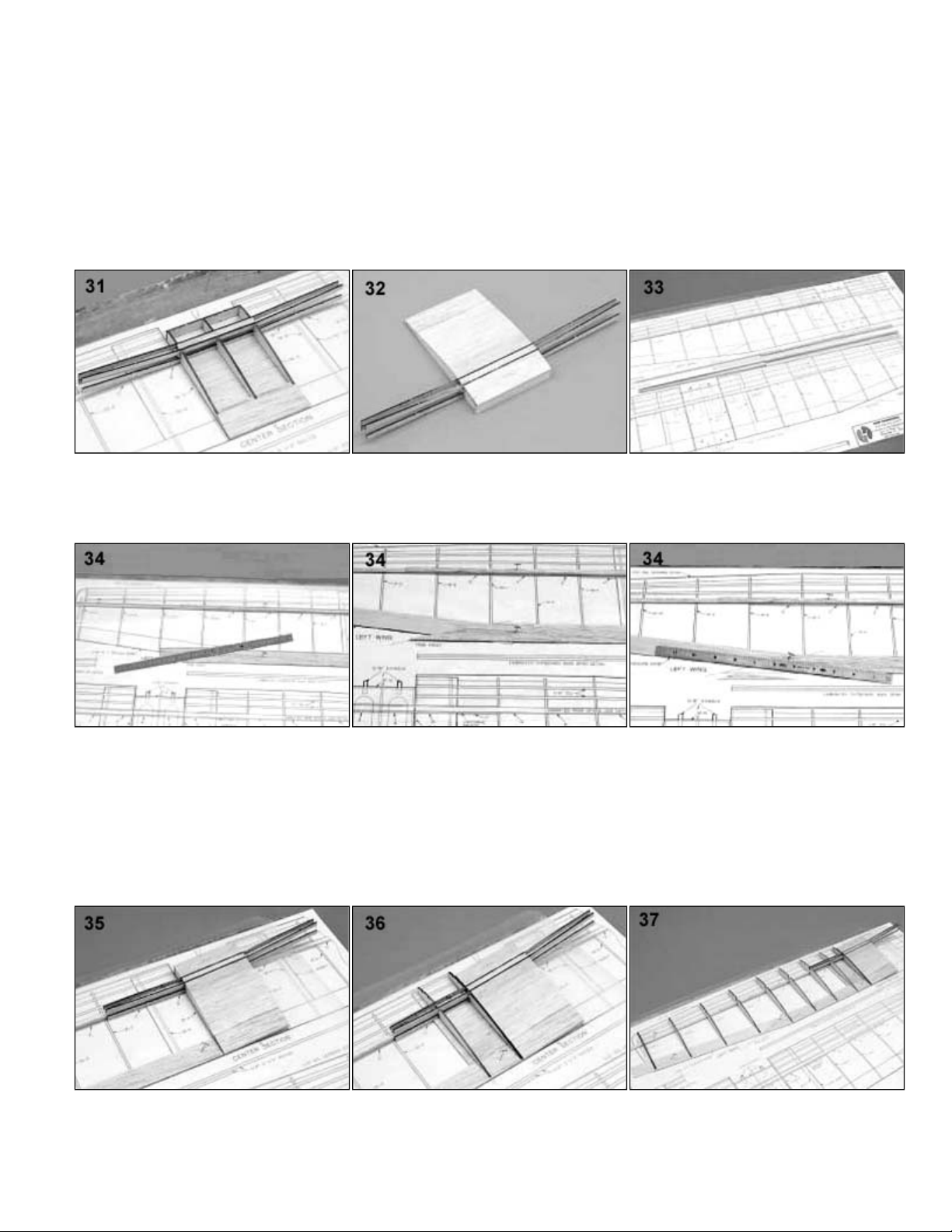
31.
Cut the forward top 1/4 sq. main spar to length and glue the two remaining dihedral braces to it as you did the lower spar.
Now glue the spar into position. Now glue the two shear webs A into position against the rear of the spars.
32.
Glue the remaining sheet to the top of the center section. The forward sheet is glued to the top of W-12 and against the
front face of the dihedral brace on the main spar. The rear sheet runs from the aft face of the main spar and the 1 trailing
edge. Now remove the center section from the plan. and trim the top and bottom sheet flush with the front of W
-
12.
33.
Laminate the four main wing spars from 1/8 x 1/4 balsa strips as shown on the plan. Pin the left hand lower outboard main
spar and the lower left trailing edge into position on the plan. The inboard ends should terminate between W-2 and W-3.
The outboard ends can be left long and be trimmed flush with the last rib after assembly.
34.
Trim the ends of the 1/16 x 1 trailing edges (where they meet at W-7) to the angles shown on the plan. Glue the trailing
edges together over the plan. When the glue is dry, trim the outer piece to match the plan. Assemble the three remaining
trailing edges as you did the first.
35.
Place the wing center section into position against the left lower spar and trailing edge. Rock the center section so that the
dihedral braces are in contact with the lower spar and are flat on the building board. Glue the dihedral braces to the
outboard main spar and glue the trailing edge to the center section.
36.
Glue the lower 1/16 sheet into position between the lower spar and the 1 lower trailing edge. Now glue ribs W-3 and W-4
into position. Rib W
-
3 should be tight against Rib W
-
2 of the center section.
37.
Glue the remaining ribs (W
-
5 thru W
-
11) into position. These ribs are to be 90 degrees to the building board.
.
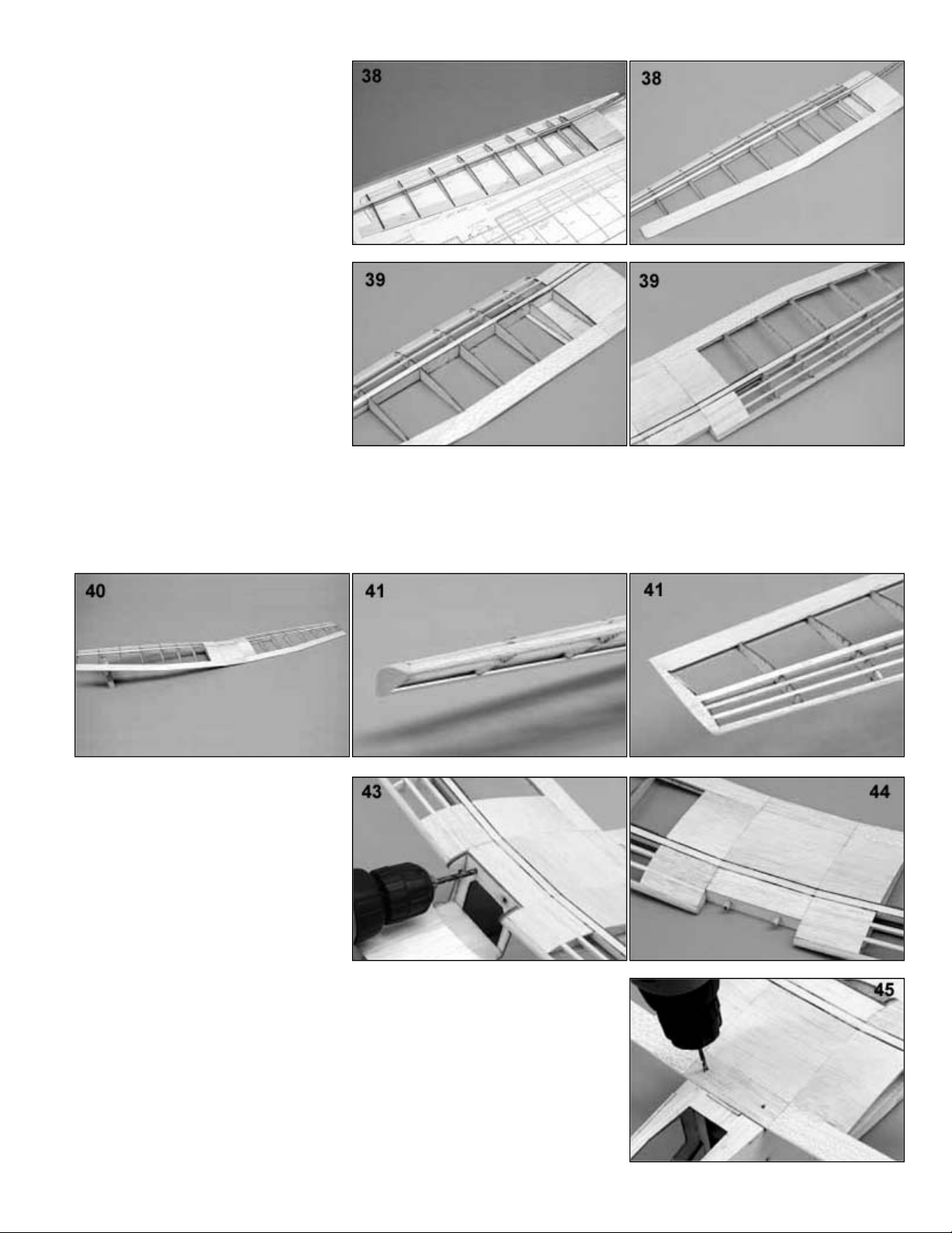
38
Glue the top main spar into position. The
inboard end should make contact with
the top spar in the center section. Glue
the 1/4 sq. leading edge into position on
the ribs. The outboard end can extend
past the last rib and be trimmed later.
Glue the top 1/16 x 1 trailing edge into
position. Glue the 1/8 sq. leading edge
strips into position.
39
Remove the wing from the plan. Sheet
the forward bottom of the wing with 1/16
sheet. Glue the shear webs B thru G into
position on the rear of the main spar.
Now sheet the top inboard end of the
wing. Trim any parts that extend past W
-
11 flush with the outboard face of W-11.
40.
Now build the right wing as you did the left. When you place the center section / left wing into position you should support
the left wing at the proper angle so that the dihedral braces for the right wing are flat against the building board.
41.
Glue the 3/4 balsa triangle wing tips into position. Trim and sand the wing tips to match the airfoil shape of rib W-11. Now
sand the leading edges round and sand the wing smooth all over.
42.
Test fit the wing onto the fuselage. You
can sand the front of W-12 or the trailing
edge if the fit is too tight. If there is any
gap between the leading edges of the
outboard panels and the fuselage you
can glue a piece of 1/16 sheet to the
outside of the W-3 rib and sand it for a
perfect fit.
43.
Use a 3/16 drill bit to drill through the
holes in F-5 and into the wing leading
edge (W-12).
44.
Remove the wing from the model and glue the two wing dowels into position. They
should stick out from W-12 about 1/4.
45.
Place the wing back on the model and mark the position of the rear hold down
screws using the plan as a guide. Drill these two holes with a 1/8 drill bit. Drill all
the way through the trailing edge and parts F-20.
46.
Remove the wing and drill out the holes IN THE WING ONLY with a 3/16 drill bit.
.
47. Squirt some thin C/A into the 1/8 holes in the F-20 s. Run a 10-32 tap down
through the holes to cut the threads for the screws. Put a little more thin C/A onto
the threads and then clean them out one last time with the tap.
48.
Mount the wing back on the model and bolt into place with the nylon screws.
Pre-Cover Assembly
49.
Sand the entire fuselage smooth and
lightly round the corners.
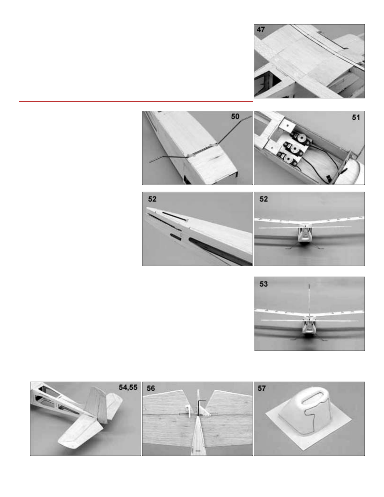
50.
Install the main landing gear wires into
the fuselage and secure with the landing
gear straps and #2 sheet metal screws.
51.
Mount the servos on F-18. Install them
according to the radio manufactures
instructions. You may trim the openings
in F-18 as needed to allow the servos to
fit.
52.
Trim the wood from the rear of the
stabilizer slot. Bolt the wing back on the
model. Now glue the stabilizer into
position on the model. Sight from the
rear to make sure that the stabilizer is
aligned properly with the wing. It should
not tilt to one side or the other.
53.
Now glue the fin into position. It should be 90 degrees to the stabilizer. Make sure
it is straight and square before gluing.
54.
Temporarily hinge (do not glue) the elevators to the stabilizer.
55.
Temporarily hinge (do not glue) the rudder to the fin.
56.
Attach the control horns to the elevator and rudder with 2
-56 screws. Bend and
install the rudder and elevator pushrods with clevises at the horns and servo
connectors at the servos.
57.
Trim the plastic cowl as shown. The rear of the cowl has been trimmed to length at the factory so you will only have to cut
out the opening in the front and make the cutout to allow clearance for the engine, muffler, and carburetor.

.
58.
Install the motor and mount. Test fit and
install the cowl using four #2 sheet
metal screws.
59.
Cut the plastic windshield to match the
pattern on the plan and test fit it to the
model. Do not glue into position until
after the model is covered.
Covering
60.
Remove the Cowl, motor, motor mount, control surfaces , landing gear, and other items. Sand the entire model smooth
with 320 grit sandpaper.
61.
Cover the model with your choice of iron on covering materials.
62.
An ultra fine Sharpie Marker can be used to draw panel lines and other details.
63.
Paint the firewall and cowl with fuel proof paint.
Final Assembly
64.
Put the tail wheel on it s axle and secure by pressing on the nylon retainer.
65.
Install the elevators and then the rudder
to the model and glue the hinges in
place.
66.
Install the control horns. Install the
pushrods and connect the pushrods to
the servos and horns.
67.
Install the landing gear. Cover parts LG.
Attach to the wire strut with a strip of
covering material. Apply a small amount
of silicone rubber to attach them to the
fuselage side. Secure the wheels to the
axles with 3/32 wheel collars.
68.
Install the engine mount to the firewall
and bolt the engine to the mount.
69.
Install the throttle pushrod.
70.
Install the receiver and battery pack.
The battery should be placed in the
nose of the model under the fuel tank.
Wrap the battery and receiver with foam
rubber. Mount the switch in the left
fuselage side. Run the receiver antenna
through the rear fuselage and out a
small hole in the fuselage side just
behind F-12 and below the stabilizer.
71.
Install the windshield on the model. First glue the top rear edge to the top of F-5. When this glue is dry, use small strips of
masking tape to hold the bottom corners in position and carefully glue the remaining edges of the windshield to the model.
.
72.
Install the cowl on the model using the #2 sheet metal screws and securely attach the propeller.
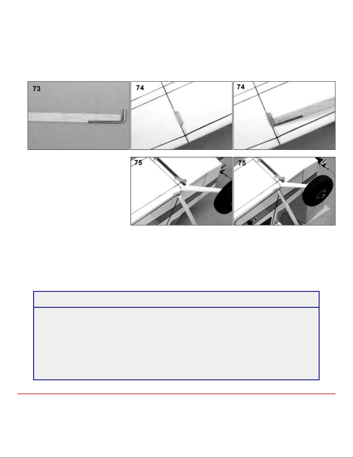
73.
The wing struts are optional. They are installed using the following procedures. Sand the edges of the strut round. Bend one
of the strut wires and glue to one end of the strut.
74.
Cut the plastic strut tube into four 1/4 lengths. Mark the strut locations on the model using the plan as a guide. Carefully
remove a 1/16 x 1/4 strip of covering at the tube mounting locations. Now glue the strut tubes to the model.
75.
Mount the wing on the model. Attach the
strut to one of the wings by sliding the
wire into the tube. Now swing the strut
against the fuselage side and cut it off so
that there is about 1/8 between the end
of the strut and the tube on the fuselage.
Now attach the lower strut wire to the
strut. Build the other strut and finish
them with covering material.
76.
Balance the model at the location shown on the plan. If necessary, add weight to the nose or tail until the model is balanced
with the fuel tank empty. Set the control throws to the measurements shown on the plan and verify that the controls move in
the proper direction.
77.
Always pre
-flight your model thoroughly before each flight. It is your responsibility to verify that your model is airworthy.
Always follow established safety guidelines and manufacturer s recommendations while starting and operating the engine,
radio, and when flying the model.
WARRANTY
Herr Engineering Corp. guarantees this kit to be free from defects in both materials and workmanship at the
time of purchase. This warranty does not cover any component damaged buy use or modification. In no case
shall Herr Engineering Corporation's liability exceed the original cost of the purchased kit. Further Herr
Engineering Corp. reserves the right to change or modify this warranty without notice.
In that Herr Engineering Corporation has no control over the assembly or use, no liability shall be assumed or
accepted for any damage resulting from the use by the user during construction of the kit or the use of the final
user assembled product. By the act of building this kit and/or using the final user assembled product, the user
accepts all liability.
If the buyer and/or user is not prepared to accept all of the liability associated with this product, he is advised to
immediately return this kit in new and unused condition to the place of purchase for a full refund.
© Copyright SIG Mfg. Co., Inc.
SIG MFG. CO., INC............Montezuma, Iowa 50171
-
0520
LIMIT OF LIABILITY:
In use of our products, Sig Mfg. Co.'s only obligation shall be to replace such quantity of the product proven to be defective.
User shall determine the suitability of the product for his or her intended use and shall assume all risk and liability in connection
therewith.
Table of contents
Other Herr Engineering Toy manuals


Popular Toy manuals by other brands

Agora Models
Agora Models Mitsubishi A6M ZERO Fighter Build instructions

Hasbro
Hasbro Trans Formers 83560 instructions

Eduard
Eduard 49 287 instruction sheet

Fisher-Price
Fisher-Price wonder builders GJF89 Builder's guide

Eduard
Eduard 32 932 manual

Tower Hobbies
Tower Hobbies Uproar V2 .46 EP ARF instruction manual


Fisher-Price
Fisher-Price Thomas & friends Y9914 instructions

USA Toyz
USA Toyz GALAXY LIGHT SWORD quick start guide

Eduard
Eduard Zoom Il-2m3 Stormovik quick start guide

Bergen
Bergen INTREPID GAS owner's manual

SIG
SIG KADET LT-40 EG Assembly manual

Fisher-Price
Fisher-Price Little People Animal Sounds Farm Series manual