Heska Element DC5X User manual

Veterinary Chemistry Analyzer Product Manual
Veterinary Chemistry Analyzer
Veterinary Chemistry Analyser
Veterinary Chemistry Analyser

2
Element DC5X
Veterinary Chemistry Analyzer
Introduction
Thank you for purchasing the Element DC5X® Veterinary Chemistry Analyzer.
The Element DC5X Veterinary Chemistry Analyzer (henceforth, the Element DC5X Analyzer) is an in vitro diagnostic medical
device for veterinary hospital use, to analyze blood by colorimetric end-point, rate and ISE tests, using the DRI-CHEM SLIDES.
Before using this instrument, please read this manual carefully to follow the precautions so that you can operate it correctly.
No part or all of this manual may be reproduced in any form without prior permission.
The information contained in this manual may be subject to change without prior notice.
FUJIFILM shall not be liable for malfunctions and damage resulting from installation, relocation, remodeling,
maintenance, and repair done by other than dealers specified by FUJIFILM.
FUJIFILM shall not be liable for malfunctions and damage of FUJIFILM products due to the use of products of other
manufacturers not supplied by FUJIFILM.
FUJIFILM shall not be liable for malfunctions and damage resulting from remodeling, maintenance, and repair using
repair parts other than those specified by FUJIFILM.
FUJIFILM shall not be liable for malfunctions and damage resulting from negligence of precautions and operating
methods contained in this manual.
FUJIFILM shall not be liable for malfunctions and damage resulting from use under environment conditions outside
the range of conditions required for proper use of this product, such as power supply, installation environment, etc.
contained in this manual.
FUJIFILM shall not be liable for malfunctions and damage resulting from natural disasters such as fires, earthquakes,
floods, lightning, etc.

i
Element DC5X
Veterinary Chemistry Analyzer
Table of Contents
SECTION 1: USING THIS MANUAL
1.1 Cautions and Warnings Used in the Manual........................................................................................................................................................................1
1.2 Operating Cautions...............................................................................................................................................................................................................................1
1.3 Biohazards and Disposal....................................................................................................................................................................................................................1
1.4 Warnings Regarding Explosives....................................................................................................................................................................................................2
1.5 Warnings Regarding Electric Shock............................................................................................................................................................................................2
1.6 Electromagnetic Compatibility (EMC).......................................................................................................................................................................................2
1.7 Caution Regarding Moving Parts.................................................................................................................................................................................................3
1.8 Installation Locations...........................................................................................................................................................................................................................3
1.9 Measurement Results..........................................................................................................................................................................................................................4
1.10 DRI-CHEM Slides .....................................................................................................................................................................................................................................4
1.11 QC Card System......................................................................................................................................................................................................................................5
1.12 SamplerCover ...........................................................................................................................................................................................................................................5
1.13 DRI-CHEM Auto Tips, Sample Tubes and DRI-CHEM Mixing Cups .........................................................................................................................5
1.14 Light Source Lamp................................................................................................................................................................................................................................6
1.15 Recording Paper......................................................................................................................................................................................................................................6
1.16 Labels ..........................................................................................................................................................................................................................................................6
SECTION 2: PART NAMES, ACCESSORIES AND OPTIONAL ITEMS
2.1 Part Names.................................................................................................................................................................................................................................................7
2.2 Touch Panel Screen Names and Functions ........................................................................................................................................................................ 10
2.2.1 Measurement preparation screen...........................................................................................................................................................................10
2.2.2 Help screen............................................................................................................................................................................................................................ 11
2.3 Names and Functions of Software Keyboard Screens.................................................................................................................................................12
2.4 Accessories.............................................................................................................................................................................................................................................. 13
2.5 Consumables and Optional Accessories.............................................................................................................................................................................. 14
2.5.1 Consumbables.....................................................................................................................................................................................................................14
2.5.2 Optional Accessories .......................................................................................................................................................................................................15
SECTION 3: MEASUREMENT
3.1 Operation Overview.......................................................................................................................................................................................................................... 16
3.2 Measurement Preparation.............................................................................................................................................................................................................18
3.3 Basic Measurements..........................................................................................................................................................................................................................20
3.3.1 Lamp off and measurement start scheduling................................................................................................................................................. 25
3.4 Measurement Results Screen......................................................................................................................................................................................................26
3.4.1 Measurements Results display .................................................................................................................................................................................. 26
3.4.2 Measurement Results screen buttons..................................................................................................................................................................28
3.4.3 Calendar display ................................................................................................................................................................................................................. 29
3.5 ISE Test Measurements ....................................................................................................................................................................................................................29

ii
3.6 Dilution Tests..........................................................................................................................................................................................................................................30
3.7 Powering Off the Element DC5X Analyzer..........................................................................................................................................................................32
3.8 Sample Tubes for the Element DC5X Analyzer................................................................................................................................................................34
3.8.1 Blood Collection Tubes .................................................................................................................................................................................................. 34
3.8.2 Producing Samples Using Sample Tubes........................................................................................................................................................... 34
3.8.3 Sample Racks........................................................................................................................................................................................................................ 35
3.9 QC Card System...................................................................................................................................................................................................................................35
3.9.1 Calculation method.......................................................................................................................................................................................................... 35
SECTION 4: APPLICABLE USAGE METHODS
4.1 Interrupting Sample Application and STAT Tests............................................................................................................................................................ 37
4.1.1 Interrupting Sample Application.............................................................................................................................................................................37
4.1.2 Requesting a STAT Test...................................................................................................................................................................................................38
4.2 Running Tests.........................................................................................................................................................................................................................................40
4.3 Slide Loading Order When Measuring Different Items Simultaneously...........................................................................................................42
4.4 Automatic Acquisition of Sample Information (Work Lists).....................................................................................................................................42
4.5 Editing Sample Numbers and Sample IDs..........................................................................................................................................................................46
4.6 Using the Sample Barcode Reader ..........................................................................................................................................................................................47
4.6.1 When Imputing the Operator ID .............................................................................................................................................................................48
SECTION 5: LOADING CONSUMABLES
5.1 Loading Consumables.....................................................................................................................................................................................................................49
5.2 Setting Tips..............................................................................................................................................................................................................................................49
5.3 Loading Mixing Cups........................................................................................................................................................................................................................51
5.4 Loading Diluent....................................................................................................................................................................................................................................53
5.5 Loading Reference Fluid.................................................................................................................................................................................................................55
SECTION 6: MAINTENANCE
6.1 Periodic Maintenance Items ........................................................................................................................................................................................................ 58
6.1.1 Items for Daily and Periodic Inspection by the User...................................................................................................................................58
6.2 Cleaning the Air Filters..................................................................................................................................................................................................................... 58
6.3 Inspecting and Cleaning the Transfer Bar, Incubator, Spotting Part and ISE Unit......................................................................................59
6.3.1 Reference Plate Level Check.......................................................................................................................................................................................59
6.3.2 Cleaning the Transfer Bar, incubator, Spotting part and ISE unit ........................................................................................................61
6.3.3 Reassembling parts and ending cleaning .........................................................................................................................................................66
6.4 Replacing Recording Paper...........................................................................................................................................................................................................67
6.5 Replacing and Cleaning the Light Source Lamp............................................................................................................................................................ 68
6.6 Inspecting and Replacing the Sampler O-ring ................................................................................................................................................................ 69
6.6.1 Performing the sampler leak check ....................................................................................................................................................................... 69
6.6.2 Replacing the sampler O-ring....................................................................................................................................................................................72
6.7 Cleaning the Slide Reading Section........................................................................................................................................................................................74
6.8 Cleaning and Replacing the Reference Fluid Cap..........................................................................................................................................................75

iii
SECTION 7: TROUBLESHOOTING
7.1 Error Display............................................................................................................................................................................................................................................ 76
7.1.1 Error Log ..................................................................................................................................................................................................................................76
7.1.2 Error Code and Reference Section Table.............................................................................................................................................................78
7.1.3 Printout Reference Table ............................................................................................................................................................................................... 80
7.2 Troubleshooting...................................................................................................................................................................................................................................81
7.2.1 Startup Errors........................................................................................................................................................................................................................81
7.2.2 Printer or LCD Trouble.....................................................................................................................................................................................................81
7.2.3 Slide Reading Errors.......................................................................................................................................................................................................... 82
7.2.4 Sampler Errors...................................................................................................................................................................................................................... 82
7.2.5 Photometric System Errors.......................................................................................................................................................................................... 85
7.2.6 Transfer Errors.......................................................................................................................................................................................................................86
7.2.7 Temperature Controller Errors ................................................................................................................................................................................... 87
7.2.8 Circuit Board Signal Errors............................................................................................................................................................................................ 88
7.2.9 QC Card and DI Card Errors......................................................................................................................................................................................... 90
7.2.10 Slide Loading Errors..........................................................................................................................................................................................................91
7.2.11 ISE Measurement Errors.................................................................................................................................................................................................91
7.2.12 Errors Related to Data Communication and Sample Barcode Reader.............................................................................................93
7.2.13 Other Errors............................................................................................................................................................................................................................93
7.3 Slide Code Table...................................................................................................................................................................................................................................94
SECTION 8: FUNCTION MENU
8.1 Function Menu .....................................................................................................................................................................................................................................95
8.2 Control .......................................................................................................................................................................................................................................................96
8.3 Normal Mode......................................................................................................................................................................................................................................... 97
8.3.1 Date and Time Settings................................................................................................................................................................................................................... 97
8.3.2 Brightness and Volume.................................................................................................................................................................................................. 98
8.3.3 Lamp Management..........................................................................................................................................................................................................98
8.3.4 Lot Information ...................................................................................................................................................................................................................99
8.4 Mode Function for Administrator.............................................................................................................................................................................................99
8.4.1 Language Setting ........................................................................................................................................................................................................... 100
8.4.2 Host Connection Setting ........................................................................................................................................................................................... 100
8.4.3 Calculated Parameter ................................................................................................................................................................................................... 102
8.4.4 Unit Conversion ............................................................................................................................................................................................................... 104
8.4.5 Switch Measurement Range Display.................................................................................................................................................................. 105
8.4.6 Reference Interval Range Setting......................................................................................................................................................................... 105
8.4.7 Sample No. and ID Settings...................................................................................................................................................................................... 107
8.4.8 Work List Selection Setting....................................................................................................................................................................................... 108
8.4.9 Correlation Coefficients .............................................................................................................................................................................................. 108
8.4.10 Lot Compensation Coefficients............................................................................................................................................................................. 112
8.4.11 Dilution Setting................................................................................................................................................................................................................ 113
8.4.12 Tube Setting for Diluent and Reference Fluid.............................................................................................................................................. 115
8.4.13 Print Setting for Measured Result......................................................................................................................................................................... 115

iv
8.4.14 Operator ID Setting ....................................................................................................................................................................................................... 116
8.4.15 Test Item Name Setting .............................................................................................................................................................................................. 116
SECTION 9: OTHER FUNCTIONS
9.1 Data Communication.................................................................................................................................................................................................................... 117
SECTION 10: SPECIFICATIONS
10.1 Specifications...................................................................................................................................................................................................................................... 118
SECTION 11: GLOSSARY
11.1 Glossary .................................................................................................................................................................................................................................................. 119
1
Element DC5X
Veterinary Chemistry Analyzer
Section 1: Using This Manual
1.1 Cautions and Warnings Used in this Manual
This section contains the safety precautions that must be followed for safe operation of the Element DC5X Analyzer. Before
using this analyzer, please read this section carefully and follow the precautions given so that it may be operated correctly.
The following section lists the meaning of precautions (marks) used in this manual.
WARNING indicates hazardous situations that may lead to serious injury, death, or the transmission of infectious agents if
the precaution is not followed.
CAUTION indicates hazardous situations that may lead to minor injury, moderate injury, or physical damage if the
precaution is not followed.
IMPORTANT indicates improper handling that could have an adverse effect on the accuracy of the measurement values
if the precaution is not followed.
NOTE: indicates procedures requiring special attention, instructions that must be followed, supplementary explanations, etc.
1.2 Operating Cautions
CAUTION
Before using this instrument, please read this Product Manual carefully so that you can operate the analyzer correctly.
CAUTION
When operating this analyzer, be sure to observe the precautions described in this manual. Failure to do so may result in
injuries, property damage, or produce incorrect test results.
CAUTION
This analyzer is an in vitro diagnostic medical device for veterinary hospital use.
Intended use of this equipment is to quantitate the concentration or the activity of the components in blood by using the
DRI-CHEM SLIDES. Do not use the equipment for other purposes.
CAUTION
This analyzer is to be operated only by personnel appropriately trained for its intended use and correct operation.
IMPORTANT
Use consumables on or before their listed expiration date.
1.3 Biohazards and Disposal
WARNING
Used consumbables such as measured slides, tips, mixing cups, sample tubes and cotton swabs and cloths used to clean
the equipment are infectious waste. Process this waste in compliance with any applicable local, state or federal regulations.

2
WARNING
When discarding the main unit that may be contaminated with blood samples, follow applicable regulations in your
country and dispose of it appropriately.
WARNING
When handling samples (blood) and performing maintenance (cleaning the analyzer), always follow biohazard procedures
(wear gloves, a lab coat, and safety goggles) in accordance with the sample handling rules of your facility. If the sample is
accidentally touched, immediately rinse the contaminated area thoroughly under running water and disinfect.
1.4 Warnings Regarding Explosives
WARNING
Do not use flammable and explosive gas around the equipment.
1.5 Warnings Regarding Electric Shock
WARNING
The voltage supplied to the equipment is AC 100–240 V. To avoid electrical shock, observe the following precautions.
• Avoid installation locations in which water may splash on the equipment.
• Plug the power cable into an outlet with a grounding receptacle. Electrical shock may occur if the equipment is not
grounded to a protective earth.
• Make sure that all cables have been properly connected.
WARNING
Do not remove covers or other parts that are secured with screws to avoid electrical shock that may result from exposure
to hazardous voltage or injury from moving parts.
1.6 Electromagnetic Compatibility (EMC)
NOTE: It is the manufacturer's responsibility to provide equipment electromagnetic compatibility information to the customer
or user. On the other hand, it is the user’s responsibility to ensure that a compatible electromagnetic environment for the
equipment can be maintained so the device will perform as intended.
This equipment conforms to the following emission and immunity requirements:
• IEC 61326–2–6:2012 (Class B)
• EN 61326–2–6:2013 (Class B)
• IEC 61326–2–6:2005 (Class B)
• EN 61326–2–6:2006 (Class B)
This analyzer has been designed and tested to CISPR 11 Class B. In a domestic environment it may cause radio interference, in
which case, you may need to take measures to mitigate the interference.
The electromagnetic environment should be evaluated prior to operation of the device.
Do not use this device in close proximity to sources of strong electromagnetic radiation (e.g., unshieided intentional RF
sources), as these may interfere with the proper operation.
If this equipment does cause harmful interference to other devices, which can be determined by tuning the equipment off
and on, the user is encouraged to try to correct the interference by one or more of the following measures.
• Reorient or relocate the receiving device.
• Increase the separation between the equipment.
• Connect the equipment into an outlet on a circuit different from that to which the other device(s) are connected.

3
CAUTION
Do not use other devices which generate and can radiate radio frequency energy near the Element DC5X Analyzer.
Otherwise, physical damage or malfunction on the Element DC5X Analyzer may occur.
1.7 Caution Regarding Moving Parts
WARNING
Do not place your fingers near moving parts (sampler and sample disk) when operating the equipment, including during
maintenance.
Also use care and do not get your fingers, hair, clothing, or accessories caught in moving parts.
WARNING
During sample processing, ensure the sampler cover is closed to prevent injuries and biohazards. If your finger touches a
tip that has sample inside, the sample may spill out from the tip. When the display reads [Ready to test], the sampler cover
can be opened.
1.8 Installation Locations
WARNING
Plug the power cable of the equipment into an outlet with a grounding receptacle. Electrical shock may occur if the outlet
is not grounded.
CAUTION
Avoid the following installation sites.
• Places where spills or water leakage may occur.
• Places where the equipment is exposed to direct sunlight.
• Places near sources of heat such as heaters.
• Places where the temperature may drastically change.
• Places where the equipment is subject to vibration or is unstable.
1. Install the equipment in the following environmental conditions.
Installation environment:
Illumination:
Indoor use (do not expose to direct sunlight)
6,000 cd/m(lux) or less (3,000 cd/m(lux) or less when
using the sample barcode reader)
Atmospheric pressure: 810 hPa or more, equivalent altitude 6,562 ft (2,000 m)
Transient overvoltage category: II
Pollution degree: 2
Operating temperature: 59°F–89°F (15°C–32°C)
Operating humidity: 30% RH–80% RH (no vapor condensation)
4
2. Use the equipment under the following electrical specifications.
Power supply voltage: Single phase AC 100–240 V ±10%
Frequency: 50 to 60 Hz
Consumption current: 3–1.3 A
Type of protection against electrical shock: CLASS 1 EQUIPMENT
3. Use an independent outlet separate from other equipment.
4. At least 4 inches (10 cm) of clearance is required on all sides of the analyzer.
5. Unplug the equipment from the AC outlet if it will not be used for an extended period of time.
CAUTION
Hold the handle of the device when lifting or moving it.
CAUTION
• When moving the device to another installation location, remove all slides, samples, diluent, reference fluid, mixing
cups, tips, and other consumables beforehand.
• Do not set the device on its side or upside down while moving it.
• Place the device on a flat and stable stand.
• When the device is subject to vibrations, such as when being moved by vehicle, it is necessary to secure the moving
parts within the device. Contact Heska Technical Support Services.
Failure to observe these precautions may result in unexpected errors or equipment malfunctions.
1.9 Measurement Results
IMPORTANT
Make a diagnosis in a comprehensive manner, considering other relevant test results or clinical symptoms.
IMPORTANT
When an equipment problem (error) appears before or during measurement, or a warning appears in the measurement
results, the measurement results may not be accurate. Refer to Section 7: Troubleshooting, and then rerun the
measurement.
1.10 DRI-CHEM Slides
NOTE: For the remainder of the manual, DRI-CHEM Slide is shortened to “slide”.
IMPORTANT
• The slides should be stored in a refrigerator still wrapped to avoid humidity, light, and heat.
• Remove the required number of slides from the refrigerator, and allow them to reach room temperature before
unwrapping and using them.
• Complete the measurement within 30 minutes after unwrapping the individual package.
Handles

5
• Do not touch either the center part of the surface or back of a colorimetric test slide.
• Do not touch the thread bridge part of an electrolyte slide.
• Do not scratch the identification information on the back of a slide.
• Do not reuse a slide.
NOTE: Slide packages and containers for liquids such as reference fluid may change without notice.
1.11 QC Card System
1. A QC card is packed together with CM (Colorimetric) slides in the same box. Before using a new lot of CM slides, read the
QC card using the card reader.
The analyzer can record up to 5 lots per test, so you can mix and use slides of different lots. Store the read QC card in the box
it came in until the accompanying lot of slides has been used up.
NOTE: When QC information exceeds 5 lots, the oldest QC information is deleted. Slides without QC information cannot be
measured.
2. A QC card contains the slide test name and the correction coefficient corresponding to the manufacturing number (lot).
Always use slides from the same box.
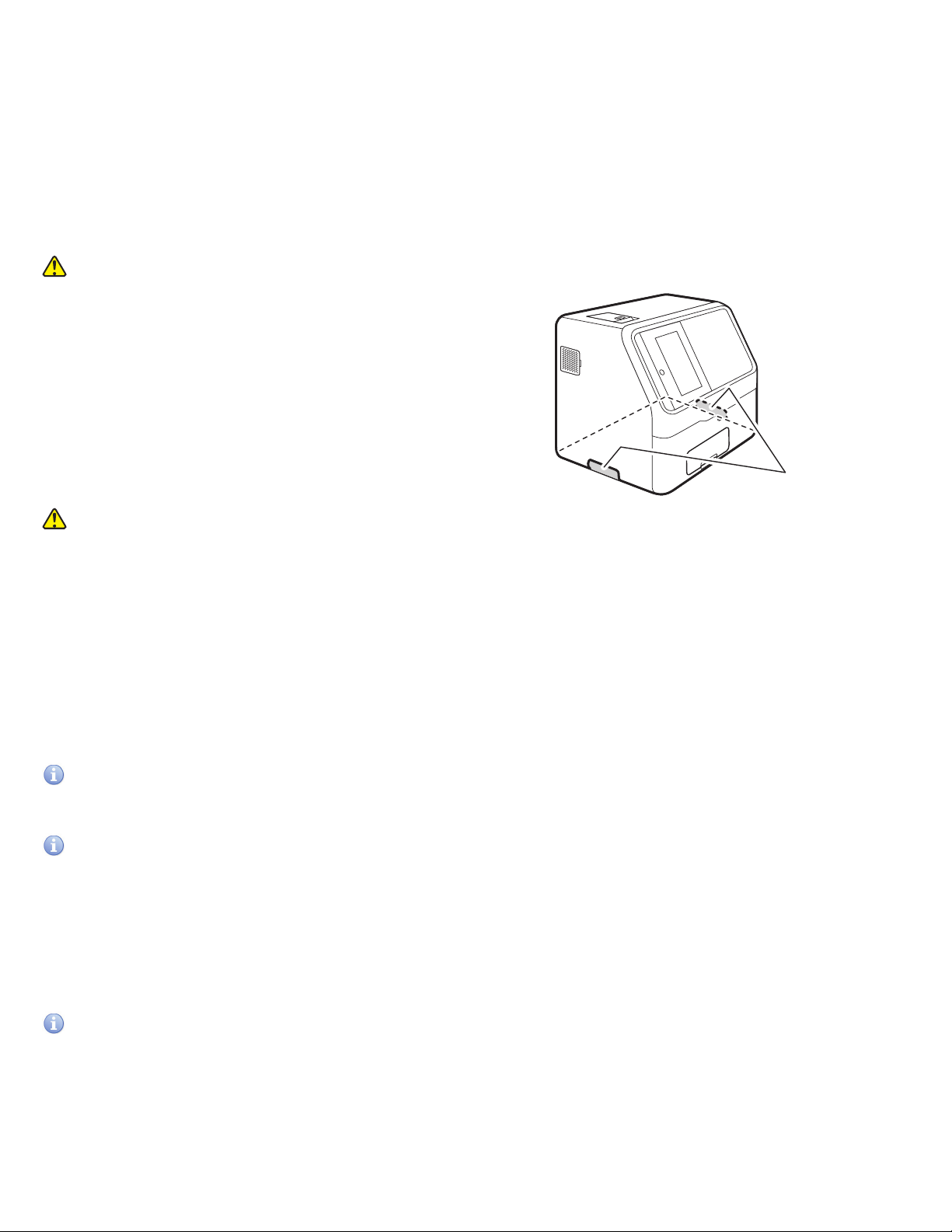
1.12 Sampler Cover
WARNING
During sample processing, ensure the sampler cover is closed to prevent injuries and biohazards. When the display reads
[Ready to test], the sampler cover can be opened.
1.13 DRI-CHEM AUTO TIPS, Sample Tubes and DRI-CHEM MIXING CUPS
NOTE: In this manual, DRI-CHEM Auto Tips may be shortened to “tip”, Sample Tube to “tube”, and DRI-CHEM Mixing Cups to
“mixing cup”.
The Element DC5X Analyzer performs sample application automatically. However, it is necessary to load the tips, samples,
tubes and mixing cups designed for use with the Element DC5X Analyzer. The sample tubes include the following types:
• HEPARIN TUBE 1.5 mL (green cap)
• HEPARIN TUBE 0.5 mL (green cap)
• PLAIN TUBE 1.5 mL (red cap)
• PLAIN TUBE 0.5 mL (red cap)
IMPORTANT
Always use new tips, sample tubes and mixing cups for each sample. Do not reuse old ones.
IMPORTANT:
When the power is shut off during test processing, such as by a power outage, replenish tips and replace mixing cups. The
analyzer may lose the information of the usage positions of the consumables and use used mixing cups.
6
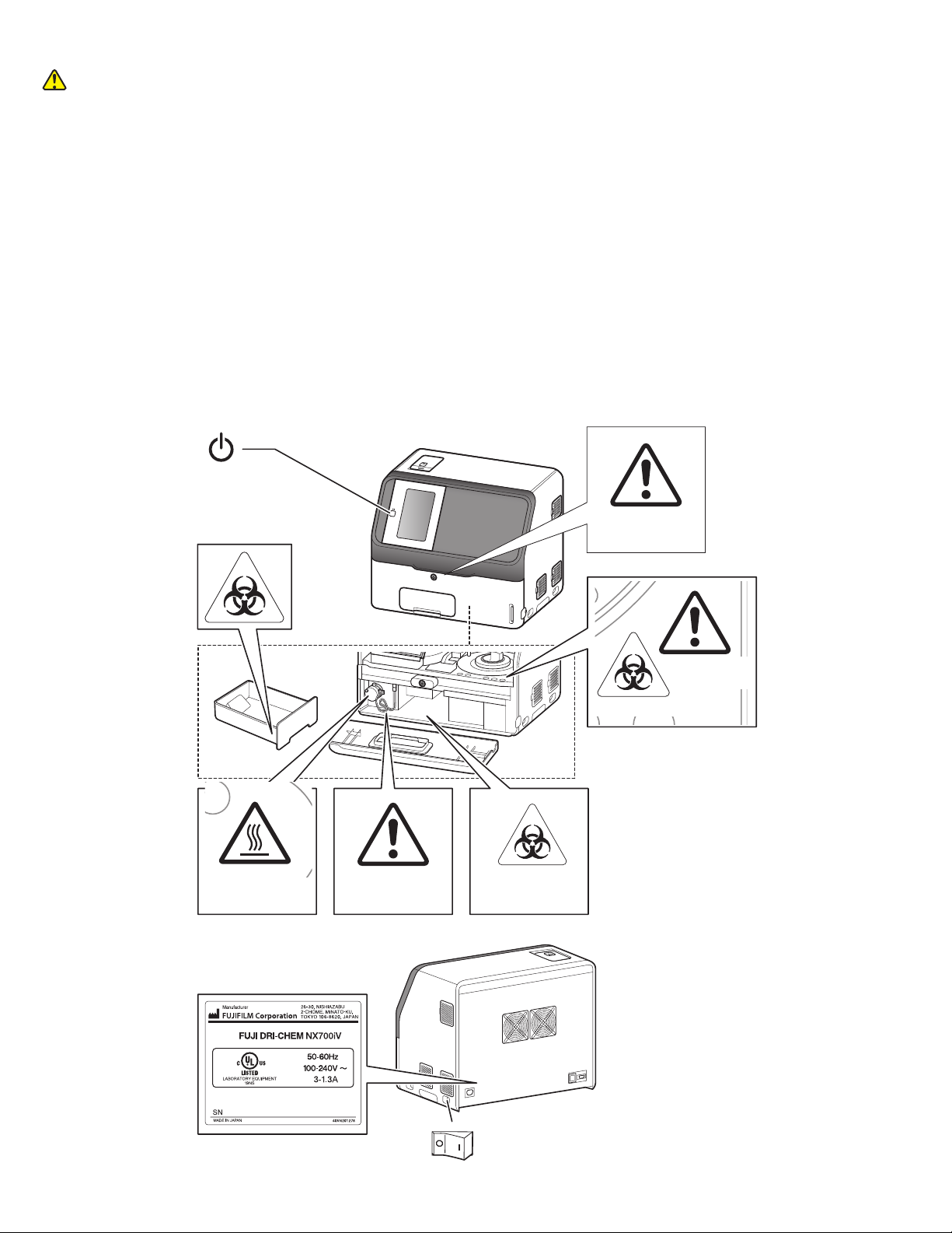
1.16 Labels
The following safety labels are affixed to the Element DC5X Analyzer.
caution label
Moving parts
Biohazard label
Biohazard label
Biohazard label
High temperature
caution label Lamp caution label
Name-plate
Power button
Power switch
| : Depress to power ON
O : Depress to power OFF
Sampler cover lock
key caution label
1.14 Light Source Lamp
CAUTION:
The light source lamp gets very hot. Before replacing the lamp, turn the power off, wait at least 5 minutes, and then check
that the lamp has cooled.
1. The light source lamp is a precision halogen lamp. Do not touch the glass surface of the lamp with your bare hands.
2. The lamp is a consumable with a lifetime. Always keep a spare lamp on hand in case the lamp burns out.
1.15 Recording Paper
1. Use specified recording paper for the Element DC5X Analyzer.
2. If other recording paper is used, the printer head section may be damaged.
7
Element DC5X
Veterinary Chemistry Analyzer
Section 2: Part Names, Accessories and Optional Items
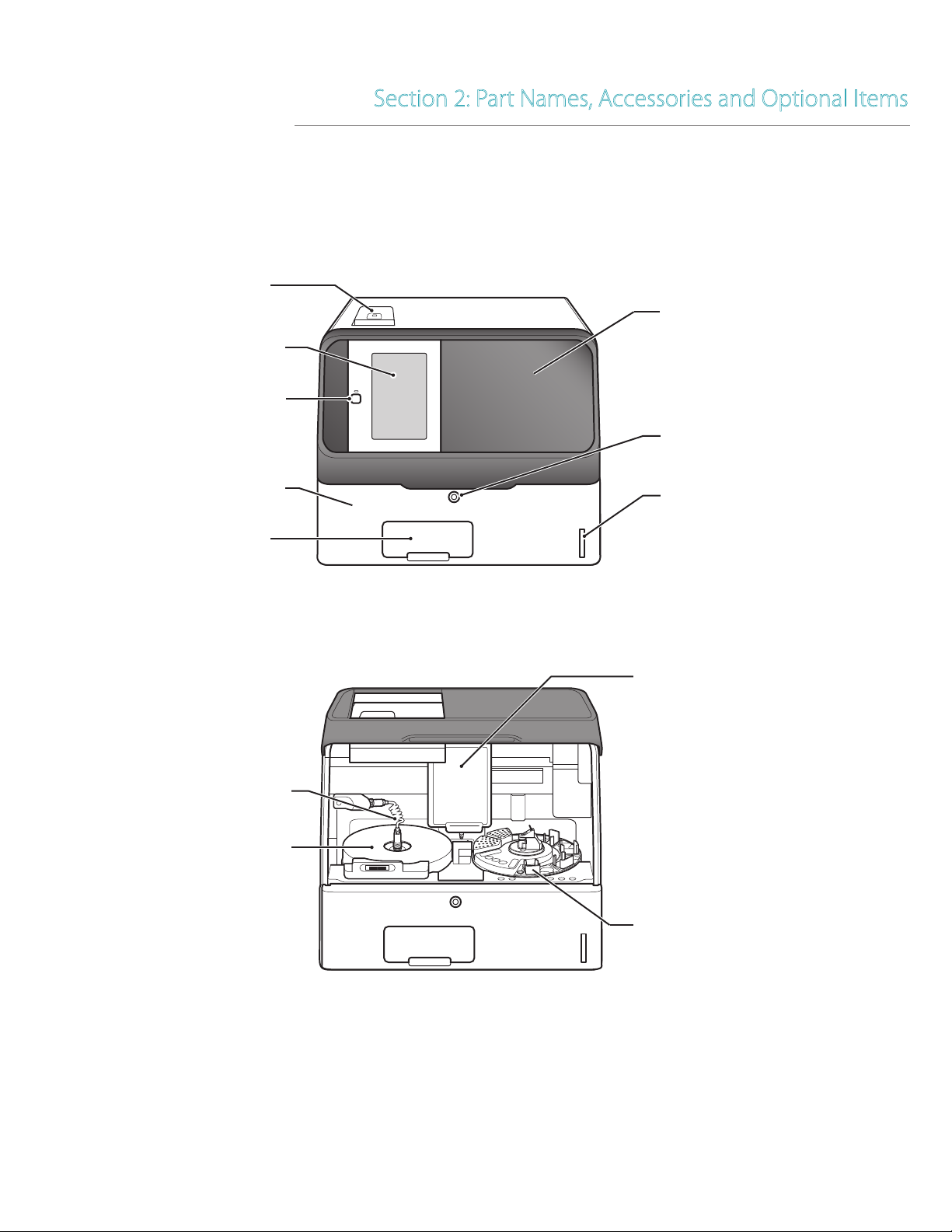
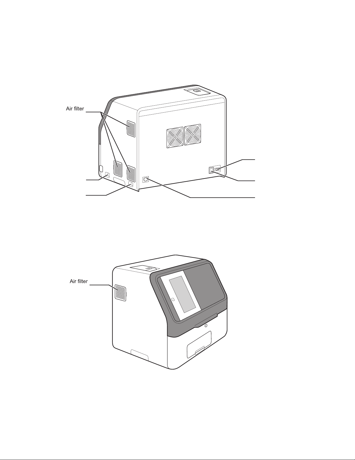
2.1 Part Names
Printer
Card reader
LCD (touch panel)
Power button
Disposal box
Sampler cover
Front bottom cover
Sampler cover lock
Incubator cable
Incubator cover
Sampler nozzle cover
Sample disk
8
USB connector
Power switch Power inlet
(Louver)
LAN terminal
RS-232C connector
(Louver)
(Louver)
(Louver)
(Louver)

9
Light source lamp
Disposal box
Sample rack (A - E)
unit cover
Sample application
Slide cartridge (A - E)
Calibrator holder
Mixing cup
Tip rack
Diluent holder (D1 - D3)

10
2.2 Touch Panel Screen Names and Functions
On the Element DC5X, the touch panel is used to perform
configurations, run measurements, confirm measurement
results and messages, and perform other operations. Because a
pressure-sensitive touch panel was employed, the screen can
be operated while wearing gloves.
2.2.1 Measurement preparation screen
If the power is switched on, the Measurement preparation screen appears after startup.
1
2
3
4
7
5
6
LCD (touch panel)
Buttons
1. HELP button
Display the help screen. Section 2.2.2
2. WORK LIST button
Obtain order information from the host PC. Section 4.4.
3. Function menu button
Display the function menu screen. Section 8
4. START button
Start a measurement.
5. OPERATOR ID button (displayed according to settings)
If touched, you can enter the operator ID. Section 8.4.16
6. PRINT button
Print all measurement results of the displayed sample.
7. PAUSE button (displayed during sample application operation)
If the PAUSE button is touched during sample application,
tips are discarded, operation stops, and the equipment enters a paused state. If PAUSE is touched again, the subsequent
sample applications are terminated.
8. MEASUREMENT RESULTS button
Display the measurement results. Section 3.4
9. Mixing cups
Displays the number of remaining mixing cups. Touch to load mixing cup. Section 5.3
10. Diluent
Touch to load diluent. Section 5.4
11. Reference fluid display
Touch to load reference fluid. Section 5.5
12. Tips
Touch to load tips. Section 5.2
13. Sample racks (A–E)
Touch sample rack and the sample information registration screen of that rack is displayed. Section 3.3

11
2.2.2 HELP screen
During measurement, maintenance, consumable exchange, and
other actions on the Element DC5X Analyzer. the ?may be touched
on the Measurement preparation screen to check the procedures.
1. X button
Touch and the Measurement preparation screen appears.
2. OK button
Touch to return to the previous screen.
2
1

12
2.3 Names and Functions of Software Keyboard Screens
When data entry for operations and configurations is necessary, the software keyboard appears on the LCD automatically.
Enter alphanumeric characters and symbols.
1. Alphabetical characters, numbers and symbols.
Enter alphabetical characters, numbers and symbols.
2. X button
Delete all entered characters, and then quit keyboard entry.
3. MOVE CURSOR buttons
Move the position of the cursor left or right by one character.
4. CLEAR button
Delete all entered characters.
5. OK button
Confirm the entered characters.
6. BACKSPACE button
Delete the character to the left of the cursor.
7. SPACE button
Enter a space of one single character width.
Change the entry screen by using the ABC, abc, 123, or -#/ button.
When the ABC button is selected
8. ABC button
Display the entry screen for uppercase alphabetical characters and
numbers.
LCD
(LCD touch panel)
1
2
5
4
7
6
3
LCD
(LCD touch panel)
1
2
5
4
7
6
3
8 9 10 11
When the [ABC] button is selected

13
2.4 Accessories
AC power cable 1
Recording paper 2
Slide cartridge 5
Slide weight 5
Light source lamp 1
O-ring 4
Tip rack 2
Sample rack (TUBE 1.5 mL type) 5
Sample rack (TUBE 0.5 mL type) 5
Sampler leak check tool 2
DRI-CHEM Auto Tips 1 case
PLAIN TUBE 1.5 (1.5 mL type) 1 pk
PLAIN TUBE 0.5 (0.5 mL type) 1 pk
DRI-CHEM Mixing Cups 1 pk
Key (for sampler cover) 2
Installation method 1
8 9 10 11
When the [ABC] button is selected
8 9 10 11
When the [ABC] button is selected
8 9 10 11
When the [ABC] button is selected
9. abc button
Display the entry screen for lowercase alphabetical characters
and numbers.
10 . 123 button
Display the entry screen for numbers, decimal ( . ) and minus
symbol (-).
11. - # / button
Display the entry screen for symbols and numbers.

14
2.5 Consumables and Optional Accessories
To purchase the consumables or optional accessories listed below, please contact your dealer.
2.5.1 Consumables
Accessories Package/unit
* DRI-CHEM Auto Tips 96 tips/box
Sample Tubes:
HEPARIN TUBE (1.5 mL) 500 × 1 box
HEPARIN TUBE (0.5 mL) 500 × 1 box
PLAIN TUBE (1.5 mL) 500 × 1 box
PLAIN TUBE (0.5 mL) 500 × 1 box
*Recording paper 3 rolls × 1 pkg
*Light source lamp 1
*O-ring 4
*DRI-CHEM Mixing Cups 50 × 1 box
NOTE: Parts names marked with “*” are the same parts packed with the Element DC5X Analyzer.
Chemicals
DRI-CHEM CONTROL QN
DRI-CHEM REFERENCE FLUID RE
NOTE: Types of packages or containers for consumables are subject to change without notice.
The requirements of the cable specifications for the Element DC5X Analyzer.
Power voltage: 100 V–120 V
Requirements for the plug/connector: AC 125 V, 10 A
Requirements for the cable: SVT 3/18 AWG 140°F (60°C)
Power voltage: 200 V–240 V
Requirements for the plug/connector: AC 250 V, 10 A
Requirements for the cable: GTCE–3 1.0 mm2 158°F (70°C)
NOTE: The AC power cable is required to be in compliance with any applicable regulations in your country.
NOTE: Do not change AC power cable to in appropriate one.
NOTE: Specifications and capabilities are subject to change without notice.
Other manuals for Element DC5X
1
Table of contents
Other Heska Measuring Instrument manuals


Popular Measuring Instrument manuals by other brands

PCB Piezotronics
PCB Piezotronics 356A14 Installation and operating manual

Keysight Technologies
Keysight Technologies N5221A Service guide

HT Instruments
HT Instruments HT9019 user manual

Zircon
Zircon SuperScan M4 user manual

Bosch
Bosch GRL2000-40HV operating instructions

SMC Networks
SMC Networks IZH10 Series manual


