Heska DRI-CHEM 4000 User manual

DRI-CHEM 4000
Veterinary Chemistry Analyzer Product Manual

2
DRI-CHEM 4000
Veterinary Chemistry Analyzer
Preface
Analyzer Description
The DRI-CHEM® 4000 Veterinary Chemistry Analyzer is a multi-parameter in-hospital chemistry analyzer produced for
multi-species veterinary applications.
Serial Number
The serial number is located on the rear of the analyzer.
Additional Documentation
Additional documentation available from Heska Corporation includes:
• Quick Steps Guide
• Installation Guide Product Bulletin
• Reference Ranges Chart
• Interfering Substances Product Bulletin
• Performance Summary Booklet
• System Performance Data
• Maintenance and Control Log
Operator Requirements
The following operator requirements must be fulfilled before operating the DRI-CHEM 4000 Veterinary Chemistry Analyzer.
• Basic skills in a laboratory environment.
• Basic skills in diagnostic chemistry.
• It is highly recommended that the operator read and understand this manual.
Optional Accessories and Consumables
Accessories and consumable lists are available from Heska Corporation. Please call 800.464.3752, option 3.

i
DRI-CHEM 4000
Veterinary Chemistry Analyzer
Table of Contents
PREFACE
SECTION 1: SAFE USAGE AND HANDLING PRECAUTIONS
Section Overview ........................................................................................................1
1.1 Definition of Specific Safety Precautions ............................................................................1
1.2 Precautions Before Operating This Equipment ......................................................................1
1.3 Biohazards and Disposal............................................................................................2
1.4 Explosive Hazards ..................................................................................................2
1.5 Electrical Hazards...................................................................................................2
1.6 Electromagnetic Capabilities (EMC).................................................................................3
1.7 Installation Site Requirements ......................................................................................3
1.8 DRI-CHEM Analyzer Slides (SD) .....................................................................................4
1.9 Calibration Card System ............................................................................................5
1.10 DRI-CHEM Analyzer Auto Tips, Sample Tubes and DRI-CHEM Analyzer Mixing Cups .................................6
1.11 Light Source Lamp .................................................................................................6
1.12 Recording Paper....................................................................................................6
1.13 Warning Labels.....................................................................................................7
SECTION 2: COMPONENT NAMES AND FUNCTIONS
2.1 Component Names ................................................................................................8
2.2 Names and Functions of Keyboard Controls ......................................................................11
SECTION 3: OPERATIONS
Section Overview ......................................................................................................15
3.1 Principles of Operations ..........................................................................................15
3.2 Detailed Operations ..............................................................................................16
3.3 Operations . . . . . . . . . . . . . . . . . . . . . . . . . . . . . . . . . . . . . . . . . . . . . . . . . . . . . . . . . . . . . . . . . . . . . . . . . . . . . . . . . . . . . . . . . . . . . . . . . . . . . . . 20
3.4 Inputting Sample ID..............................................................................................25
SECTION 4: PERIODIC MAINTENANCE
4.1 Cleaning the Air Filter ............................................................................................29
4.2 Cleaning the Incubator and ISE Unit ..............................................................................29
4.3 Cleaning the Slide Reader and the Spotting Part..................................................................33
4.4 Replacing the Recording Paper ..................................................................................34
4.5 Replacing and Cleaning the Light Source Lamp ..................................................................35

ii
4.6 Inspecting and Replacing the Sampler O-ring ....................................................................37
4.6.1 Inspecting the Sampler O-ring ............................................................................37
4.6.2 Replacing the Sampler O-ring .............................................................................38
4.7 Replacing the Fuse ...............................................................................................39
SECTION 5: TROUBLESHOOTING
Section Overview ......................................................................................................40
5.1 Error Indications..................................................................................................40
5.1.1 Error Code Table ..........................................................................................40
5.1.2 Printout Indication Table ..................................................................................42
5.1.3 About Measurement Range ...............................................................................42
5.2 Troubleshooting .................................................................................................43
5.2.1 Startup Errors .............................................................................................43
5.2.2 Display or Printer Trouble..................................................................................43
5.2.3 Slide Reading Errors .......................................................................................44
5.2.4 Sampler Errors ............................................................................................44
5.2.5 Photometer Errors.........................................................................................50
5.2.6 Transfer Errors .............................................................................................52
5.2.7 Temperature Control Errors................................................................................53
5.2.8 Circuit Board Malfunction .................................................................................54
5.2.9 Calibration Card Read Error................................................................................56
5.2.10 Slide Loading Errors .......................................................................................57
5.2.11 Errors Related to Electrolyte Tests..........................................................................57
5.2.12 Errors Related to Data Communication or Sample Barcode Reader ........................................59
5.2.13 Other Errors ...............................................................................................59
SECTION 6: MODE SETTINGS AND FUNCTIONS
6.1 Mode Function List and Mode Selection..........................................................................62
6.1.1 Mode List .................................................................................................62
6.1.2 How to Select Each Mode.................................................................................63
6.2 Mode Functions..................................................................................................65
6.2.1 Mode 0 Changing Mode Type <Normal>..................................................................65
6.2.2 Mode 19 Turning on the Control Mode (a, b canceled) <Normal> .........................................66
6.2.3 Mode 20 Setting Date and Time <Normal>................................................................67
6.2.4 Mode 23 Displaying and Resetting the Lamp’s Cumulative Illumination Time <Normal> ...................68
6.2.5 Mode 24 Unit Conversion [Unit (A)/Unit (B) Switch] <Admin.>.............................................69
6.2.6 Mode 25 Data Retransmission to Host Computer <Normal>...............................................71
6.2.7 Mode 26 Reprinting Test Results <Normal> ...............................................................72
6.2.8 Mode 27 Sample No. and Sample ID Settings <Admin.>...................................................73
6.2.9 Mode 28 Switching Display Method for Values Outside of the Determination Range <Admin.> .............74

iii
6.2.10 Mode 29 Printing Out Slide Lot Number <Normal> .......................................................75
6.2.11 Mode 30 Work List Display Item Setting <Admin.> ........................................................76
6.2.12 Mode 35 Editing sample No. and sample ID <Admin.> ....................................................77
6.2.13 Mode 36 Correlation Coefficients (a, b) Settings and Printout <Admin.> ...................................79
6.2.14 Mode 37 Lot Compensation Coefficients (c, d, e) Settings and Printout <Admin.> .........................84
6.2.15 Mode 39 Reference Interval Settings and Printout <Admin.> ..............................................88
6.2.16 Mode 40 Setting Spotting Count <Admin.> ...............................................................90
6.2.17 Mode 42 Leak Check <Admin.> ...........................................................................91
6.2.18 Mode 44 Lamp off Selection <Admin.> ...................................................................93
6.2.19 Mode 45 Dilution Factor Settings <Admin.>...............................................................94
6.2.20 Mode 46 Selecting Communication Destinations <Admin.>...............................................96
6.2.21 Mode 49 Printing out Error Logs <Normal> ...............................................................99
6.2.22 Mode 52 Reference Plate Level Check <Normal> .........................................................100
6.2.23 Mode 55 Selecting Language <Admin.> .................................................................101
6.2.24 Mode 76 Printing out DI card information <Normal> .....................................................101
6.2.25 Mode 81 Alarm Sound Settings <Admin.> ...............................................................102
6.2.26 Mode 82 Display Brightness and Print Density <Admin.> .................................................103
6.2.27 Mode 83 Test Result Print Sheet Setting <Admin.> .......................................................105
6.2.28 Mode 85 Display Order of Reference Interval Names <Admin.>...........................................105
6.2.29 Mode 86 Editing and inputting Reference Interal Names <Admin.> ......................................106
6.2.30 Mode 103 Displaying Temperature and Humidity <Normal> .............................................107
SECTION 7: DATA COMMUNICATION...................................................................................108
SECTION 8: SPECIFICATIONS/CONSUMABLES
8.1 Specifications ...................................................................................................109
8.1.1 Standard Accessories.....................................................................................110
8.2 Consumables and Optional Accessories .........................................................................111
8.2.1 Consumables ............................................................................................111
8.2.2 Optional Accessories .....................................................................................111
8.3 Slide Code Table.................................................................................................112
SECTION 9: GLOSSARY ................................................................................................113

1
DRI-CHEM 4000
Veterinary Chemistry Analyzer
Section Overview
This section contains safety precautions which must be followed for the safe operation of the DRI-CHEM Analyzer. Before
using this equipment, please read this chapter carefully and follow the precautions so that you can operate it correctly.
1.1 Definition of Specific Safety Precautions
Specific safety precautions are noted by the terms WARNING, CAUTION, IMPORTANT, and additional information by
NOTE. The respective meanings are as follows:
WARNING
Indicates hazardous situations that may lead to serious injury, even death or transmission of infectious agent if the
warning is not followed.
CAUTION
Indicates hazardous situations that may lead to minor or moderate injury or physical damage if the caution is not
followed.
IMPORTANT
Indicates improper handling that could have an adverse effect on the accuracy of the measurement values.
NOTE: Indicates procedures requiring special attention, instructions that must be followed, supplementary
explanations, etc.
1.2 Precautions Before Operating This Equipment
CAUTION
Before using this equipment, please read this User Manual carefully so you can operate it correctly.
CAUTION
When operating this equipment, be sure to observe the precautions described in this manual. Failure to
do so may result in injuries, property damage, or incorrect test results.
CAUTION
Intended use of this equipment is to quantitate the concentration or the activity of the components in blood by
using the DRI-CHEM Analyzer Slides. Do not use the equipment for other purposes. Please read the Instructions for
Use for the slides. This equipment is only to be operated by personnel appropriately trained for the intended use and
operation.
CAUTION
In the mode functions described in Section 6, there are 2 kinds of modes: one is the administrator mode, which can
only be operated by administrators; another is the normal mode, which can be operated by normal operators. The
important modes, which affect test results such as Mode 36 (correlation coefficients settings), can only be operated
in the administrator mode. The administrator modes must be operated only by the administrators who have the
responsibility for the use of the analyzer. Inputting a password in Mode 0 allows the administrators to operate the
administrator modes.
Section 1: Safe Usage and Handling Precautions

2
CAUTION
Intended use of this equipment is to quantitate the concentration or the activity of the components in blood by
using the DRI-CHEM Analyzer Slides. Do not use the equipment for other purposes. Please read the Instructions for
Use for the slides. This equipment is only to be operated by personnel appropriately trained for the intended use and
operation.
CAUTION
In the mode functions described in Section 6, there are 2 kinds of modes: one is the administrator mode, which can
only be operated by administrators; another is the normal mode, which can be operated by normal operators. The
important modes, which affect test results such as Mode 36 (correlation coefficients settings), can only be operated
in the administrator mode. The administrator modes must be operated only by the administrators who have the
responsibility for the use of the analyzer. Inputting a password in Mode 0 allows the administrators to operate the
administrator modes.
1.3 Biohazards and Disposal
WARNING
Used (contaminated) consumables (e.g., DRI-CHEM Analyzer Slides, DRI-CHEM Analyzer Auto Tips, DRI-CHEM Analyzer
Mixing Cups and sample tubes) and contaminated swabs or cloths used for cleaning the equipment are infectious
waste and should be processed in compliance with any applicable local, state or federal regulations.
WARNING
When discarding the DRI-CHEM Analyzer body that may be contaminated with blood samples, be sure to process it
correctly in compliance with any applicable regulations.
WARNING
When handling samples (blood or urine), slides, tips and cleaning the analyzer or performing maintenance (cleaning
the analyzer), always follow biohazard procedures (e.g., wearing gloves, lab coat, and safety goggles). If any part of the
body comes in contact with samples, or contaminated supplies or equipment,immediately rinse the contaminated
body part thoroughly under running water and disinfect.
1.4 Explosive Hazards
WARNING
Do not to use flammable and explosive gas around the equipment.
1.5 Electrical Hazards
WARNING
The power supply voltage applied to the equipment is AC100–240V.
To avoid electrical shock, observe the following precautions:
• Avoid installation sites where water may splash on the equipment.
• Plug the power cable of the equipment into an outlet with a grounding receptacle. Electrical shock may occur, if
the equipment is not grounded to a protective earth.
• Make sure that all cables have been properly connected.
WARNING
Do not remove covers or other parts that are secured with screws, as electrical shock may result from hazardous
voltage or injury from moving parts.

3
1.6 Electromagnetic Compatibility (EMC)
This equipment conforms to the following EMC requirements:
EN61326:1997 + A1:1998 + A2:2001 + A3:2003 (Class A)
FCC Part 15 Subpart B: 2006, Class A
ICES-003 Issue No. 4, Class A
This is a Class A product. In a domestic environment, this product may cause radio interference in which case the user
may be required to take adequate measures.
This equipment has been tested and found to comply with the limits for a Class A digital device, pursuant to
Part 15 of the FCC Rules. These limits are designed to provide reasonable protection against harmful interference when
the equipment is operated in a commercial environment. This equipment generates and can radiate radio frequency
energy and, if not installed and used in accordance with the instruction manual, may cause harmful interference to radio
communications. Operation of this equipment in a residential area may cause harmful interference in which case the user
will be required to correct the interference at his own expense.
This Class A digital apparatus complies with Canadian ICES–003.
Cet appareil numerique de las class A est conforme a la norme NMB-003 du Canada.
If this equipment does cause harmful interference to other devices, which can be determined by turning the equipment
off and on, the user is encouraged to try to correct the interference by one or more of the
following measures:
• Reorient or relocate the receiving device.
• Increase the separation between the equipment.
• Connect the equipment into an outlet on a circuit different from that to which the other device(s)
are connected.
Consult the manufacturer or field service technician for help.
CAUTION
Do not use other devices which generate and can radiate radio frequency energy near the DRI-CHEM Analyzer.
Otherwise, physical damage or malfunction may occur.
1.7 Installation Site Requirements
WARNING
Plug the power cable of the equipment into an outlet with a grounding receptacle. Electrical shock may occur if the
equipment is not grounded to a protective earth.
CAUTION
Avoid the following installation sites:
• Places where spills or water leakage may occur.
• Places where the equipment is exposed to direct sunlight.
• Places near hot sources such as heaters.
• Places where temperature drastically changes.
• Places where the equipment is subject to vibration or is unstable.

4
1. Install the equipment in the following environmental conditions:
Location: Indoor Use
Illumination: Below 6000 cd/m2(lux)
(Below 3000 cd/m2(lux) when using the sample barcode reader)
Altitude: Up to 2000m (6,500 ft)
Transient overvoltage category: II
Pollution degree: 2
Operating temperature: 59°F to 89°F (15°C to 32°C)
Operating humidity: 30% to 80% RH (no dew condensation)
2. Use the equipment under the following electrical requirements:
Voltage limit: 100–240 V
Frequency: 50–60 Hz
Supply voltage fluctuations: ±10%
Rated wattage: 200 VA
Phase: Single
Type of protection against electrical shock: CLASS 1 EQUIPMENT
3. Plug the DRI-CHEM Analyzer into an independent AC outlet separate from other devices.
4. At least 10 cm (4 inches) of clearance is required on all sides.
5. Unplug the equipment from the AC outlet if it will not be used for an extended period of time.
1.8 DRI-CHEM Analyzer Slides (SD)
(Henceforth, DRI-CHEM Analyzer Slides (SD) is shortened into "slide" in this manual).
IMPORTANT
The slides should be stored in a refrigerator (2–8°C, 36–46°F) without opening the individual packages to avoid
humidity, light, and heat.
• Only the required number of slides should be taken out of the refrigerator and warmed up to room temperature
before opening the individual packages.
• Use immediately after opening the individual package.
• Do not touch either the center part of the surface or the back of the colorimetric test slides.
• Do not touch the thread bridge part of the electrolyte slide.
• A new slide must be used for each measurement. Do not reuse.
NOTE: If slides have not been used and are still in their wrappers, they may be placed back in a refrigerator as long as they
are the first to be used the next day.
NOTE: Types of slide packages and containers for liquids (e.g., diluent, reference fluid) are subject to change without
notice.

5
List of DRI-CHEM Analyzer Slides
Classification Test Name
Biochemical Tests
Enzymes
ALP Alkaline Phosphatase
AMY Amylase
CPK Creatine Phosphokinase
GGT Gamma Glutamyltransferase
GOT/AST Aspartate Aminotransferase
GPT/ALT Alanine Aminotransferase
LDH Lactate Dehydrogenase
LIP Lipase
General Chemistry
ALB Albumin
BUN Blood Urea Nitrogen
Ca Calcium
CRE Creatinine
GLU Glucose
IP Inorganic Phosphorus
Mg Magnesium
NH3 Ammonia
TBIL Total Bilirubin
TCHO Total Cholesterol
TG Triglyceride
TP Total Protein
UA Uric Acid
Electrolytes
Na Sodium
K Potassium
Cl Chloride
NOTE: Specifications and capabilities are subject to change without notice.
1.9 Calibration Card System
1. Calibration cards are packed together with slides in the same box. Before you start using a new lot of slides, read the
Calibration card using the Calibration card reader. It is advisable to store the Calibration card in the box it came in until
the accompanying lot of slides has been used.
2. Read the calibration card when the display shows [Ready], [Warming Up], or [Lamp Off].

6
1.10 DRI-CHEM Analyzer Auto Tips, Sample Tubes, and DRI-CHEM Analyzer Mixing Cups
(Henceforth, DRI-CHEM Analyzer Auto Tip is shortened into "tip," Sample Tubes into "Sample tubes," and DRI-CHEM
Analyzer Mixing Cups into "mixing cup" in this manual).
The sampler of the DRI-CHEM Analyzer performs pipetting automatically. However, it is necessary to load the Auto Tip,
Sample Tubes (Heparin or Non-Heparinized Tube), and Mixing Cups designed for use with the DRI-CHEM Analyzer.
The Sample Tubes include the following:
• HEPARIN TUBE 1.5 ml (green cap)
• HEPARIN TUBE 0.5 ml (green cap)
• NON-HEPARINIZED TUBE 1.5 ml (red cap)
• NON-HEPARINIZED TUBE 0.5 ml (red cap)
IMPORTANT
Use new tips, Sample Tubes, and cups for each sample. Do not reuse old ones.
IMPORTANT
Do not use products other than specified products designed for the DRI-CHEM Analyzer, as using non-specified
products could cause inaccurate test results and damage the analyzer.
1.11 Light Source Lamp
WARNING
The light source lamp gets very hot. Before replacing the lamp, turn the power off and wait at least 5 minutes.
1. The light source lamp is a halogen lamp. Do not touch the glass surface of the lamp with bare hands.
2. The lamp is expendable. A spare lamp should be readily available in case the lamp burns out.
1.12 Recording Paper
1. Use specified recording paper for the DRI-CHEM Analyzer.
2. Do not use paper other than the type specified, as this could damage the printer head.

7
200VA
200VA
1.13 Warning Labels
Warning labels and safety labels on the DRI-CHEM Analyzer are:
• High temperature caution label
• Lamp caution label
• Biohazard label
• Chemicals caution label
• Power switch
• Name plate

8
DRI-CHEM 4000
Veterinary Chemistry Analyzer
2.1 Component Names
Section 2: Component Names and Functions
CF Card Slot
Display
CF card slot

9
CAUTION
Do not connect the RS–232C connector to a sample barcode reader other than specified for the DRI-CHEM Analyzer.
Do not connect the RS–232C or USB connector to a computer or PC which has not been approved by IEC/UL60950–1.
(Refer to Section 6.2.20)
Do not connect an external printer to the RS–232C or USB connectors.
10

11
2.2 Names and Functions of Keyboard Controls
DISPLAY
Displays the status of the "analyzer" and the
operating procedures.
COUNTDOWN
Displays estimated time (sec.) to complete current
measurements on the analyzer.
REFERENCE
Displays a selected reference interval (e.g., DOG).
SAMPLE
Displays a selected sample type.
Cover lock LED
The LED lights when the sampler cover is locked
during sample processing.

12
MODE KEY
The MODE key is used to enter Mode functions.
ID KEY
The ID key is used to input sample numbers or sample IDs.
WORK LIST KEY
The WORK LIST key is provided for requesting patient ID and test
request information (work list) from an external PC.
REF. KEY
The REF. key is used for selecting a species reference interval.
NUMERIC KEYS
The numeric keys are used for inputting alphanumeric
characters during sample No./ID input or mode operations.
PERIOD KEY
The period key is used for inputting a decimal point.
MINUS KEY
The − (Minus) key is used for inputting the minus(−) sign.
ABC KEY
The ABC key is used for selecting either alphabetical or
numerical character input mode.
ABC indicator light
When the alphabetical character input mode has been selected,
the ABC indicator light will be on.
C (clear) KEY
The clear key is used for deleting incorrect input data.
MODE
ID
WORK
LIST
REF.
09
-
ABC
ABC
C

13
ENTER KEY
The ENTER key is used for completing data input.
SAMPLE KEY
The SAMPLE key will be used for selecting sample types. The
sample type changes each time the key is pressed. The order of
change is P/S (plasma/serum), U (urine) and W (whole blood).
The U + W functions are not used with Heska's current slide set.
RERUN KEY
The RERUN key is used for rerunning tests with the
previous sample. The test will be performed using the previous
sample No., sample ID and reference interval.
DILUTION KEY
The DILUTION key is used for setting the dilution factor.
CAL KEY
The CAL key is used for performing calibration for immuno-
chemical tests. This function is not used with Heska's current
slide set.
FEED KEY
The FEED key is used for advancing recording paper in the
printer. The paper advances one line each time the key is
pressed.
PRINT KEY
The PRINT key is used for printing data during mode operations.
SCROLL KEYS
The scroll keys are used for moving the cursor during key input
or selecting a menu.
ENTER
SAMPLE
RERUN
DILUTION
CAL
FEED
PRINT

14
STOP KEY
The STOP key is used for stopping a sampling process. The
sampler stops after discarding tips. To restart the sampling
process, load new tips into the sample rack and press the START
key. This key is also used for stopping alarms and terminating a
mode process.
START KEY
The START key is used to start testing. If tests have not been run
for more than 20 minutes, the light source lamp turns off. When
START is pressed, the light will turn on and Warming Up will be
displayed.
STOP
START

15
DRI-CHEM 4000
Veterinary Chemistry Analyzer
Section Overview
Following is an overview of the operations and processes used to obtain test results. Detailed operation procedures begin
with Section 3.2.
3.1 Principles of Operations
Slide loading:
The analyzer can compensate for the differences between the slide production lots by reading the Calibration card
included with each box of slides. The slides are unwrapped and loaded in the slide cartridge after they reach room
temperature. An electrolyte (ISE) slide can be loaded in the cartridge with colorimetric (CM) slides. The cartridge can
contain a maximum of 20 slides at one time. The analyzer identifies the test name and slide lot by scanning the printed
information on the back side.
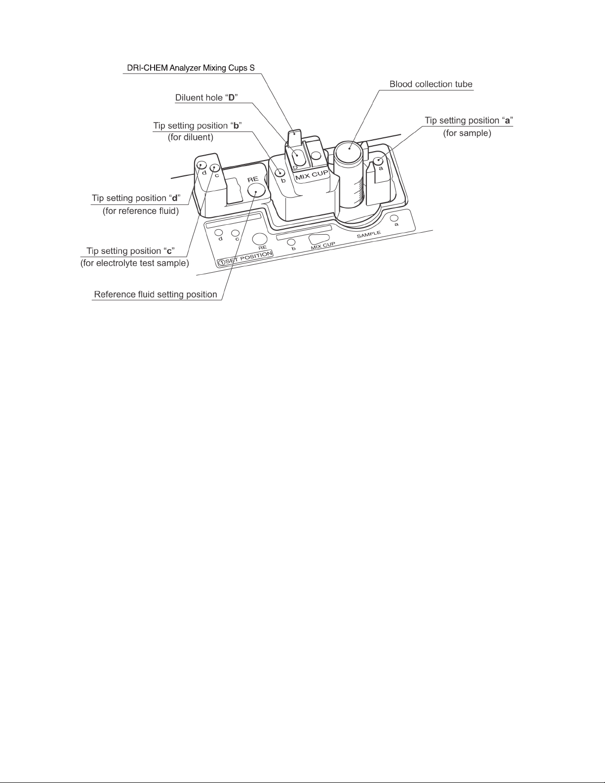
Sample loading:
Specific sample tubes (0.5 ml and 1.5 ml) are used. Sample volume to be aspirated is automatically determined for each
tube. When running electrolyte tests, reference fluid must also be loaded. When diluting the sample automatically, a mixing
cup with diluent must be loaded.
Sampling and spotting:
The sampler detects the surface of the sample, aspirates the required volume of sample, and spots it on the slide. In
dilution mode, the sampler dilutes the sample with diluent, and spots it on the slides. The spotted slide is transferred into
the incubator.
Incubation:
The incubator can hold a maximum of 6 colorimetric slides and 1 electrolyte slide. Colorimetric slides are incubated for
up to 6 minutes (varies by test) at 98.6°F (37°C) and an electrolyte slide for 1 minute at 86°F (30°C). If slides remain in the
cartridge, they will be transferred one by one into the incubator until the cartridge is empty.
Photometer and potentiometer readout:
The photometer head below the incubator reads the reflectance of the colorimetric slides as well as the white reference
plate and the black reference plate. The analyzer uses the reflectance readings, together with the reference readings, the
standard curves, and the calibration information to determine the concentrations of the samples. The potentiometer
head below the incubator reads the potential of the electrolyte slide. The analyzer determines the concentrations of the
electrolyte in the sample using the potential readings, together with the standard curves. The test results are printed out,
and can be transmitted to an external computer if desired.
Consumable disposal:
Used slides and tips are discarded into the disposal box. The used sample tube, mixing cup with diluent, and reference fluid
must be removed by hand.
Section 3: Operations
Table of contents
Other Heska Measuring Instrument manuals


Popular Measuring Instrument manuals by other brands


Dwyer Instruments
Dwyer Instruments VP2 Specifications-installation and operating instructions

EML
EML ARG314 user manual

Riken Keiki
Riken Keiki GX-8000 operating manual

Aeris
Aeris A300 XT quick start guide

ICS Schneider Messtechnik
ICS Schneider Messtechnik HYDROTECHNIK MultiHandy 2025 operating instructions

Tractel
Tractel Dynarope HF36/3/LPT Operation and maintenance manual