Hessaire 36X370-N User manual
Instruction Manual
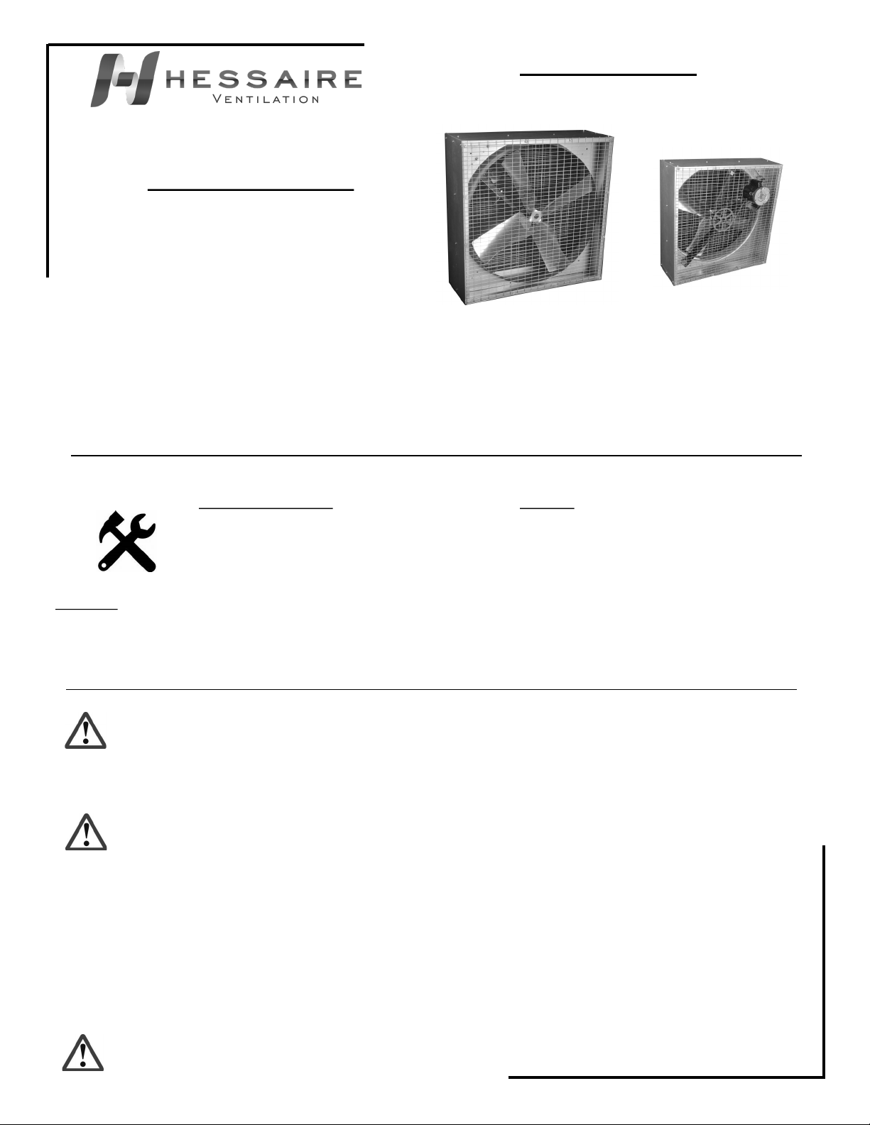
Galvanized Box Fans—Belt Drive
Please read and save these instructions. Read carefully before attempting to assemble, install, operate or maintain the equipment described
within this manual. Carefully follow all safety information.
Save this manual for future reference.
Model # _______________________________
Purchase Date: _________________________ Date: 06/13/17
Form: HV0020 Version 2
Model Numbers Covered:
36X370-N, 36X550-N, 36X550S-N,
48X750-N, 48X750S-N
Getting Started
Tools/Materials Needed:
• Drill/drill bits
• 5/16” nut driver
• Construction screws
• Caulk or sealant
Contents:
• Galvanized box fan(1)
• Instruction manual(1)
Inspection:
After unpacking your exhaust fan, carefully inspect for any damage that may have occurred during transit. Inspect for loose, missing or damaged
parts. If there is physical damage to any parts of the fan, a freight claim must be filed with the carrier. Check to assure that all bolts, screws and
set screws are securely tightened and have not become loose during transit. Retighten as required. Rotate propeller by hand to assure it turns
freely.
General Safety Instructions
Danger: Before installing or servicing, always lock out and tag power source. Do not rely on a switch as the only means
of disconnecting power. Failure to disconnect power can result in fire, electrical shock or serious injury. Motor will restart without
warning after thermal protector trips. Do not touch an operating motor as it may be hot enough to cause injury. Do not place any body
parts or objects in fan or drive components while fan is connected to a power source.
Warning:
1. Read and follow all instructions, cautions, dangers and warnings. Failure to do so could result in personal injury, death or property damage.
2. Make sure the electrical power source conforms to the requirement of the fan(s) as well as local codes.
3. Electrical connections, installation and maintenance must be done by qualified electrical personnel in accordance with all applicable codes and
ordinances.
4. Unit must be adequately grounded.
5. To reduce the risk of fire or electrical shock, do not expose this fan to water.
6. Do not touch electrically live components.
7. Free rotation of the propeller is critical. It must not touch any part of the venturi, framework or drive components.
8. Assure that all power cords do not come in contact with any sharp edges, hot surfaces or chemicals. Immediately replace any damaged cords.
Caution: OSHA requires OSHA compliant guards when fan is installed within 7ft of the floor or working level.
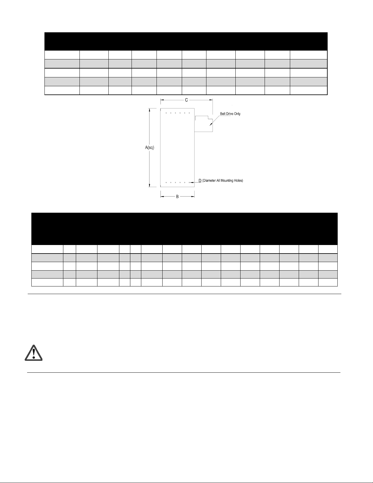
Specifications
Dimension (In.) Rough-in Opening
Model Prop Dia. A B CDHeight Width Ship Wt Ship. Dims.
36X370-N36” 40 1/8 14 18 3/8 40 3/4 40 3/4 110 44x22x47
36X550-N36” 40 1/8 14 18 3/8 40 3/4 40 3/4 115 44x22x47
36X550S-N36” 40 1/8 17 21 3/8 40 3/4 40 3/4 130 44x25x47
48X750-N48” 52 1/8 17 22 3/8 52 7/8 52 7/8 128 56x26x58
48X750S-N48” 52 1/8 20 25 3/8 52 7/8 52 7/8 150 56x29x58
Performance
CFM CFM/Watt
Model HP F.L.A. Volt. Ph Hz Motor
RPM
0.00"
SP
0.05"
SP
0.10"
SP
0.15"
SP
0.00"
SP
0.05"
SP
0.10"
SP
0.15"
SP
Db
0.00"
SP
36X370-N1/2 4.8/2.4 115/230 160 1725 10,850 9,990 9,020 7,200 18.4 16.5 14.6 11.4 73
36X550-N 3/4 7.2/3.6 115/230 160 1725 11,598 10,757 10,052 9,277 19.3 17 15.3 13.7 74
36X550S-N 3/4 7.2/3.6 115/230 160 1725 11,010 10,219 9,549 8,813 18.6 16.4 15.6 13.1 74.8
48X750-N19.0/4.5 115/230 160 1725 19,608 18,228 16,773 15,347 21.6 19.5 17.3 15.4 77.9
48X750S-N19.0/4.5 115/230 160 1725 19,210 17,499 16,185 14,825 20.9 18.8 16.5 14.7 78.2
Fan Installation
Caution: Before operating your new fan, check blade for proper torque, check all fasteners for tightness and assure
screens and/or shutters are securely in place.
For framing dimensions, refer to rough-in opening height and width shown in the specifications above.
Position the fan for desired airflow. Air will discharge on the side of the fan facing the propeller.
Assure the fan is fastened securely in the opening to avoid excess “rattling” or vibration using proper fasteners. Fasteners not included.
Refer to motor nameplate for wiring diagram.
Maintenance
Periodic maintenance schedules should be set to assure reliability and performance of the fan. This maintenance should included inspection of all
fasteners, propeller torque and proper cleaning of the complete fan assembly.
Check for excessive vibration while fan is running.
Periodically inspect and tighten all set screws and hardware.
Assure all mounting hardware, chains, etc. are properly secured.
Motors feature permanently sealed ball bearings and require no further lubrication.
The fan propeller should be periodically cleaned to assure proper balance and performance.
Grease pillow block bearings seasonally. Use caution not to apply too much grease as it may damage the seals.
Periodically check for proper belt alignment.
Troubleshooting Guide
Symptom Possible Cause(s) Corrective Action
Fan will not start 1. Tripped circuit breaker 1. Reset circuit breaker
2. Defective motor 2. Repair or replace
3. Incorrectly wired 3. Shut off power, check for proper connections
4. Electricity turned off 4. Contact local power company
Excessive noise or vibration 1. Blade is hitting housing 1. Free blade of obstruction
2. Blade is bent 2. Replace blade
3. Fan not securely anchored 3. Secure properly
4. Bad/noisy bearings 4. Replace motor
Insufficient airflow 1. Incorrect voltage applied 1. Wire properly
2. Defective motor 2. Replace motor
3. Propeller is damaged 3. Replace propeller
4. Blocked Airflow 4. Remove obstructions
5. Not enough intake air 5. Add additional air intake openings
6. Fan is dirty 6. Clean fan guards/screens, motor and propeller
Motor overheats or trips out 1. Over/under line voltage 1. Contact local power company
2. Defective motor 2. Replace motor
3. Fan is dirty. 3. Clean fan guards/screens, motor and propeller
4. Not enough intake air 4. Add additional air intake openings
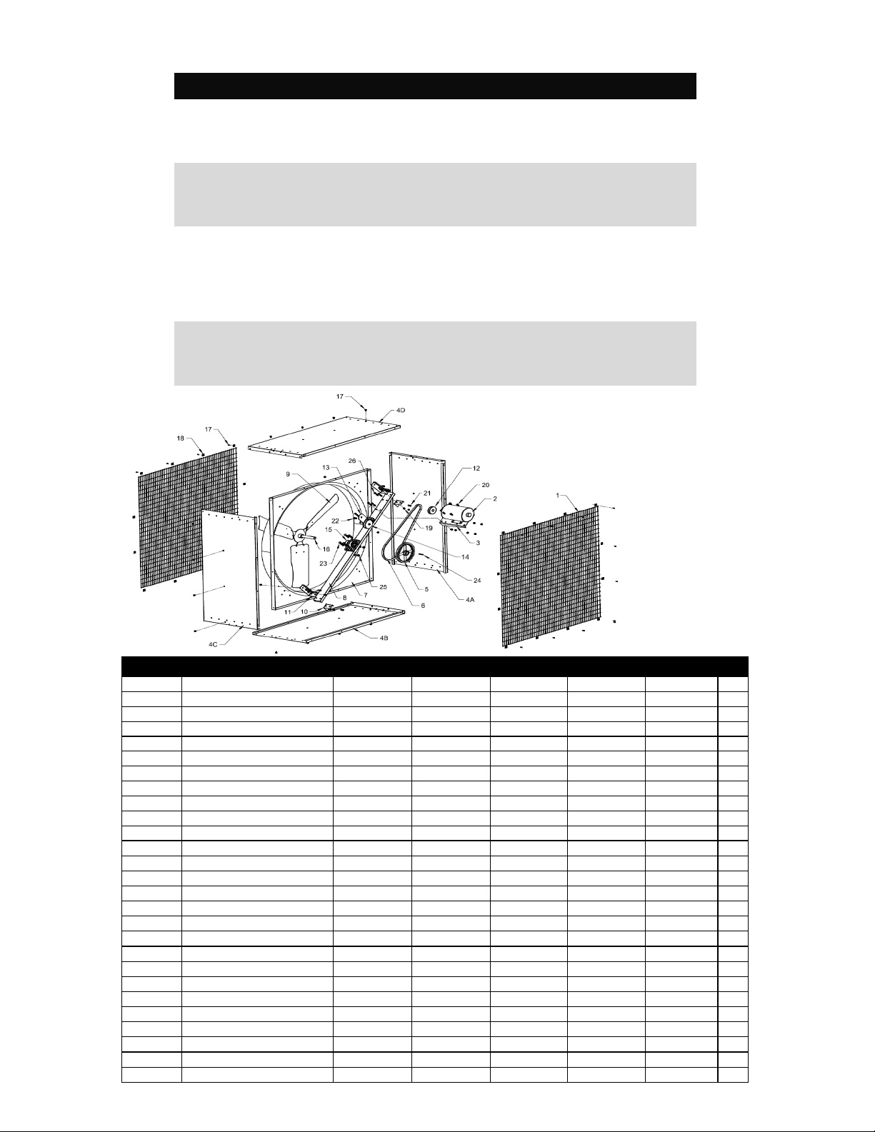
Ref No Description 36X550-N48X750-NQty48X750S-N36X550S-N36X370-N
1 Intake & Discharge screen 36SCREEN-N 48SCREEN-N 2, 148SCREEN-N36SCREEN-N36SCREEN-N
2 Motor A550-4CE A750-4CE 1A750-4CEA550-4CEA370-4CE
3 Motor mounting plate N/A N/A 1N/AN/AN/A
4(A,B,C,D) Side housing panels N/A N/A 4N/AN/AN/A
5 Large drive pulley AL94 AL94 1AL94AL94AL94
6 V belt, cogged AX51 AX61 1AX61AX51AX51
7 Venturi panel N/A N/A 1N/AN/AN/A
8 Horizontal frame piece N/A N/A 1N/AN/AN/A
9 Propeller 9001565 9001489 1900148990015659001565
10 Horizontal frame bracket, small N/A N/A 2N/AN/AN/A
11 Horizontal frame bracket, large N/A N/A 2N/AN/AN/A
12 Motor pulley AK3958 AK3258 1AK3258AK3958AK3958
13 Tensioner bracket(optional) N/A N/A 1N/AN/AN/A
14 Belt tensioner(optional) BTI BTI 1BTIBTIBTI
15 Bearing UCP205-16 UCP205-16 2UCP205-16UCP205-16UCP205-16
16 Fan shaft, 1" FS7.5 FS7.5 1FS7.5FS7.5FS7.5
17 Self tapping screw S002 S002 48S002S002S002
18 Clip for holding screen CLIP-SC CLIP-SC 24CLIP-SCCLIP-SCCLIP-SC
19 Locking nut, 5/16-18 N004 N004 19N004N004N004
20 Carriage bolt, 5/16-18X3/4" B014 B014 4B014B014B014
21 Hex head bolt, 5/16-18X1" B011 B011 6B011B011B011
22 Hex head bolt, 3/8-16X3/4" B019 B019 1B019B019B019
23 Hex head bolt, 3/8-16X1 1/4" B006 B006 4B006B006B006
24 Keyway, 1/4"X1/4" N/A N/A 2N/AN/AN/A
25 Locking nut, 3/8-16 N003 N003 4N003N003N003
26 Hex head bolt, 5/16-18X1 3/4" B015 B015 9B015B015B015
- Alum Discharge Shutter N/A N/A SA36X-N SA48X-N 1N/A
Repair Parts Illustration
Note:
Aluminum discharge shutter not shown.

Hessaire Products, Inc. provides the following limited warranty which is valid from the date of the invoice to the original purchaser on all products
that are tested and/or verified by Hessaire to be defective in materials and/or workmanship.
This limited warranty applies only to products used for the intended purpose under normal use. A two year limited warranty applies to all products
unless noted as an exception below.
This warranty does not cover failures, defects or malfunctions due to the following:
• Normal wear and tear
• Improper installation and operation, installation and operation not in accordance with instructions
• Misuse, abuse, negligence, alteration or accident
• Freight or transportation damage
• Product modifications
• Neglect or lack of maintenance
In addition, this warranty does not cover:
• Return freight or delivery costs
• Removal, installation and associated labor costs
• Loss of time, inconvenience, labor, use of product or other consequential or incidental damages
• Cosmetic rust, corrosion, staining
• Products missing proper labeling or nameplates
Terms:
Defective products will be repaired or replaced at the option of Hessaire. For installed, assembled fans, Hessaire will provide replacement parts
only and will not replace entire assembly.
Defective products shall only be returned to Hessaire with the approval of Hessaire and at the customer’s expense.
Replacement products or repair parts under warranty will be shipped to the customer at the expense of Hessaire products.
Field repairs/replacements will be performed by the customer at the customer’s expense.
Products with warranty periods other than the standard two year limited warranty:
• 12HAFO, 20HAFO
• 18” non-stainless fans
• All aluminum intake shutters
• Shutter opening gear motor kit
• Inflation blowers and related accessories
• Evaporative coolers
• All replacement parts
Effective date: January 1, 2016
Product Warranty Policy
This manual suits for next models
4


