Abicor Binzel ABICOOLER 1300 User manual

EN - 2
ABICOOLER 1300
EN Translation of the original operating instructions
1 Identification.................................................................................................................................EN-3
1.1 Marking .............................................................................................................................................EN-3
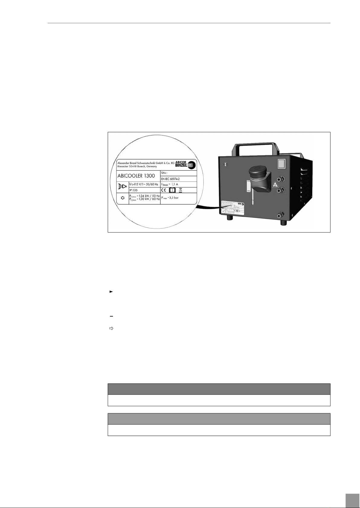
1.2 Nameplate.........................................................................................................................................EN-3
1.3 Signs and symbols used ...................................................................................................................EN-3
1.4 Classification of the warnings ..........................................................................................................EN-3
2 Safety ..............................................................................................................................................EN-4
2.1 Designated use..................................................................................................................................EN-4
2.2 Obligations of the operator .............................................................................................................EN-4
2.3 Warning and notice signs ................................................................................................................EN-4
2.4 Basic safety instructions ....................................................................................................................EN-5
2.5 Safety instructions for the power supply .........................................................................................EN-6
2.6 Personal protective equipment (PPE)...............................................................................................EN-6
2.7 Emergency information.....................................................................................................................EN-6
3 Scope of delivery........................................................................................................................EN-6
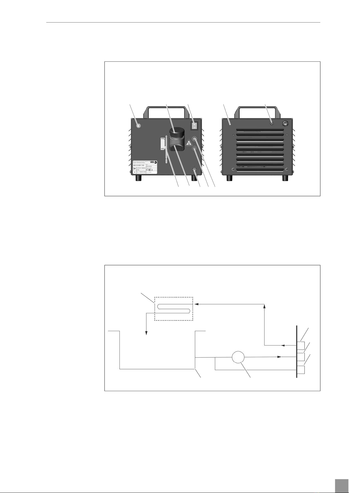
4 Product description ....................................................................................................................EN-7
4.1 Assembly and use .............................................................................................................................EN-7
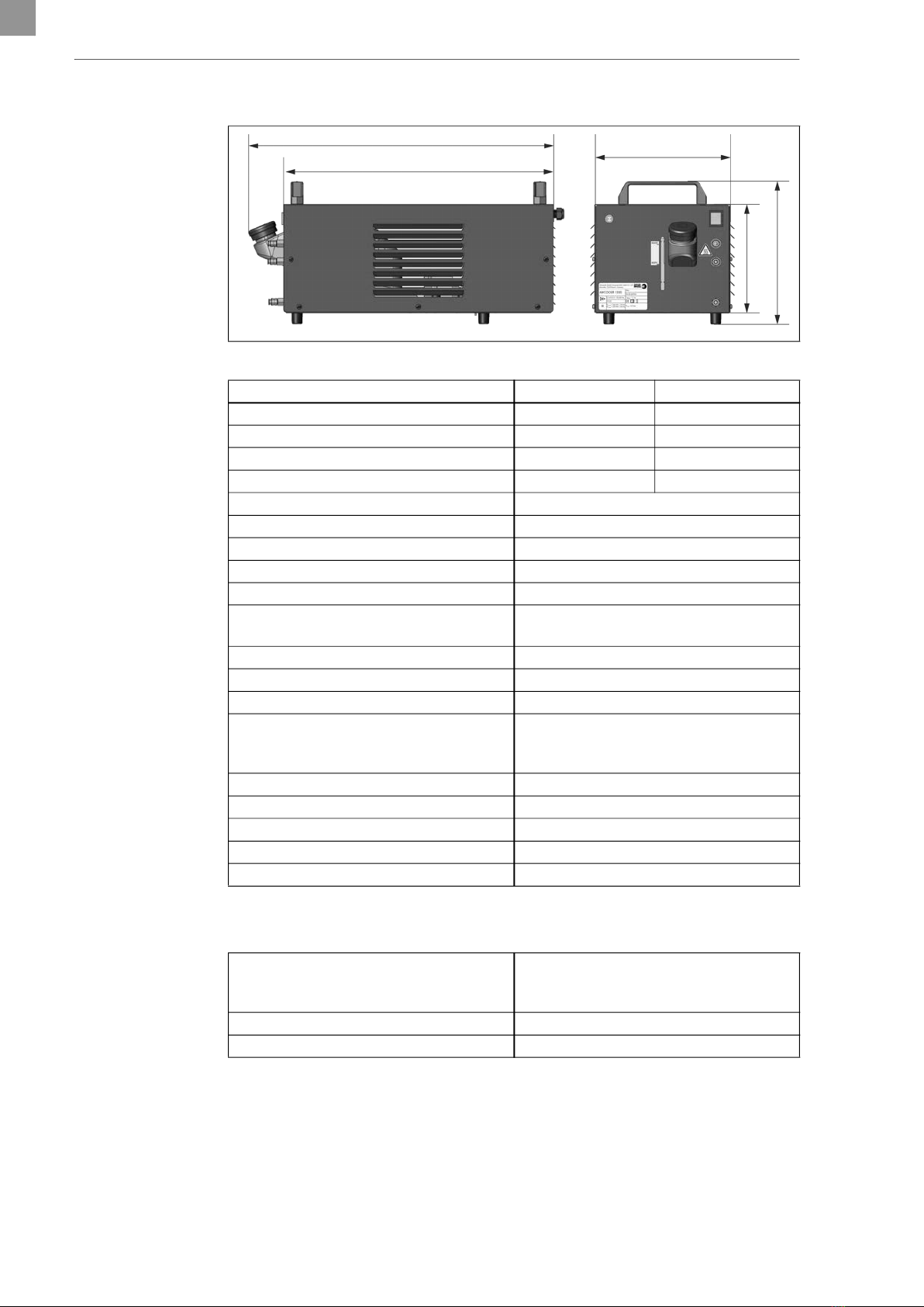
4.2 Technical data...................................................................................................................................EN-8
5 Transport and installation.......................................................................................................EN-9
6 Commissioning.......................................................................................................................... EN-10
6.1 Fuse protection for the device....................................................................................................... EN-10
6.2 Initial commissioning.......................................................................................................................EN-11
6.2.1 Bleed the device..............................................................................................................................EN-11
6.2.2 Bleeding the cable assembly ........................................................................................................ EN-13
6.2.3 Commissioning the flow control.................................................................................................... EN-13
7 Operation.................................................................................................................................... EN-14
7.1 Prior to initial commissioning and after a longer standstill......................................................... EN-14
8 Decommissioning..................................................................................................................... EN-14
9 Maintenance and cleaning .................................................................................................. EN-15
9.1 Maintenance and cleaning intervals............................................................................................ EN-15
9.2 Change the coolant ....................................................................................................................... EN-16
9.3 Replacing the fuse.......................................................................................................................... EN-16
9.4 Replacing the handles ................................................................................................................... EN-17
10 Troubleshooting ....................................................................................................................... EN-18
11 Disassembly ............................................................................................................................... EN-19
12 Disposal ....................................................................................................................................... EN-19
12.1 Disposing of materials ................................................................................................................... EN-19
12.2 Disposing of consumables.............................................................................................................EN-20
12.3 Packaging ....................................................................................................................................... EN-20
13 Appendix ....................................................................................................................................EN-20
13.1 Connecting diagram for flow control ........................................................................................... EN-20
13.2 ABICOOLER 1300 circuit diagram for 115 V............................................................................. EN-21
13.3 ABICOOLER 1300 circuit diagram for 230 V............................................................................ EN-22
13.4 Spare parts ..................................................................................................................................... EN-23
14 Warranty..................................................................................................................................... EN-23

ABICOOLER 1300 1 Identification
EN - 3
1 Identification
The ABICOOLER 1300 cooling unit is used by industry and the trade sector exclusively for the cooling of
liquid-cooled welding torches. These operating instructions only describe the ABICOOLER 1300 cooling
unit. When used in these operating instructions, the terms “device”, “product”, and “cooling unit” always
refer to the ABICOOLER 1300 cooling unit. The device may be used only with original ABICOR BINZEL
spare parts. The device is available in 230 V and 115 V versions.
1.1 Marking
This product fulfills the requirements that apply to the market to which it has been introduced.
A corresponding marking has been affixed to the product, if required.
1.2 Nameplate
The device is labeled by means of a nameplate on the housing.
► You will need the device type, device number and serial number as indicated on the nameplate for
inquiries.
1.3 Signs and symbols used
The following signs and symbols are used in the operating instructions:
1.4 Classification of the warnings
The warnings used in the operating instructions are divided into four different levels and shown prior to
potentially dangerous work steps. The following signal words are used depending on the type of hazard:
Fig. 1 Nameplate
General instructions.
Action(s) to be carried out in succession.
Lists.
Cross-reference symbol refers to detailed, supplementary or further information.
Caption, item description.
1
A
DANGER
W
Describes an imminent threatening danger. If not avoided, it may cause severe injuries or death.
WARNING
W
Describes a potentially dangerous situation. If not avoided, this may result in death or serious injuries.

EN - 4
2 Safety ABICOOLER 1300
2 Safety
This chapter describes the essential safety requirements and warns of residual hazards that should be kept
in mind to operate the product safely. Non-observance of the safety instructions may result in risks to the life
and health of personnel, and environmental damage or material damage.
2.1 Designated use
The device described in these operating instructions may be used only for the purpose and in the manner
described in these operating instructions. The device is used in industry and in the trade only for cooling
liquid-cooled welding torches. Any other use is considered improper. Unauthorized modifications or
changes to enhance the performance are not permitted.
► Do not exceed the maximum load data as defined by the documentation supplied. Excessive loads lead
to irreparable damage.
► Do not make any constructive changes to this product.
► Do not use or store the device outdoors where it is wet.
2.2 Obligations of the operator
► Ensure that only qualified personnel are permitted to perform work on the device or system.
Authorized personnel are:
— those who are familiar with the basic regulations on occupational safety and accident prevention;
— those who have been instructed on how to handle the device;
— those who have read and understood these operating instructions;
— those who have been trained accordingly;
— those who are able to recognize possible risks because of their special training, knowledge, and
experience.
► Keep untrained persons out of the work area.
2.3 Warning and notice signs
The following warning, notice and mandatory signs can be found on the product:
These markings must always be legible. They may not be covered, obscured, painted over, or removed.
CAUTION
W
Describes a potentially harmful situation. If not avoided, this may result in slight or minor injuries.
NOTICE
Describes the risk of impairing work results or material damage and indicates irreparable damage to the
device or equipment.
► Wear eye protection.
Warning against hot surfaces. Risk of burns.
► Do not touch hot surfaces.
Electrical voltage caution. Danger of electric shock.
► Only a trained electrician should open the device.
► Interrupt the electrical power supply before opening the device.

ABICOOLER 1300 2 Safety
EN - 5
2.4 Basic safety instructions
The product has been developed and manufactured in accordance with state-of-the-art technology and the
recognized safety standards and regulations. Inevitable technical residual risks to the user, third parties,
devices, or other material property are posed by the product. The manufacturer will accept no liability for
damage caused by non-observance of the documentation.
► Before using the system for the first time, please read the provided documentation carefully.
► Do not operate the product unless it is functioning properly and ensure compliance with all documents.
► Before carrying out specific work, for example, commissioning, operation, transport and maintenance,
read the documentation carefully.
► Use suitable means to protect yourself and bystanders from the hazards listed in the documentation.
► Store the documentation within easy reach of the device for reference and enclose all documents when
passing on the product.
► Consult the documentation for additional welding components.
► Information about how to handle gas cylinders can be found in the instructions provided by the gas
manufacturer and the relevant local regulations, e.g., regulations that apply to compressed air.
► Observe the local accident prevention regulations.
► Only trained specialists should commission, operate, and service the device. Qualified personnel are
persons who, based on their special training, knowledge, experience and due to their knowledge of the
relevant standards, are able to assess the tasks assigned to them and identify possible dangers.
► Keep the work area in order. Ensure good lighting of the work area.
► Switch off the power supply, gas supply, and compressed air and unplug the power plug for the entire
duration of maintenance, commissioning, and repair activities.
► For disposal, observe the local regulations, laws, provisions, standards and guidelines.
Safety instructions for electrical components
► Check electric tools for damage and for its proper functioning in accordance with its designated use.
► Do not expose electric tools to rain and avoid a moist or wet environment.
► Protect yourself from electric shock by using insulating mats and wearing dry clothing.
► Do not use the electric tools in areas subject to fire or explosion hazards.
Safety instructions for welding
► Arc welding may cause damage to the eyes, skin and hearing. Note that other hazards may arise when
the device is used with other welding components. Therefore, always wear the prescribed personal
protective equipment as defined by local regulations.
► Any metal vapors, especially lead, cadmium, copper and beryllium are harmful. Ensure sufficient
ventilation or extraction. Do not exceed the current threshold limit values (TLV).
► To prevent the formation of phosgene gas, rinse workpieces that have been degreased with chlorinated
solvents using clean water. Do not place degreasing baths containing chlorine in the vicinity of the
welding area.
► Adhere to the general fire protection regulations and remove flammable materials from the vicinity of
the welding work area prior to starting work. Provide appropriate fire extinguishing equipment in the
workplace.
Safety instructions for personal protective equipment
► Do not wear loose fitting clothing or jewelry.
► Use a hair net for long hair.
► Wear safety goggles, protective gloves, and a respiratory mask, if necessary.

EN - 6
3 Scope of delivery ABICOOLER 1300
2.5 Safety instructions for the power supply
► Ensure that the mains connecting cable is not damaged, for example, by being driven over, crushed or
torn.
► Check the mains connecting cable for damage and wear at regular intervals.
► If it is necessary to replace the mains connecting cable, only models indicated by the manufacturer may
be used.
► Only a trained electrician should replace the mains connecting cable and the mains plug.
► Splash-water protection and mechanical stability must be ensured when replacing the mains plug of the
mains connecting cable.
2.6 Personal protective equipment (PPE)
► Wear your personal protective equipment (PPE).
► Ensure that others in close proximity are also wearing personal protective equipment.
Personal protective equipment consists of protective clothing, safety goggles, a class P3 respiratory mask,
protective gloves, and safety shoes.
2.7 Emergency information
In the event of an emergency, immediately disconnect the following supplies: Electrical power supply.
3 Scope of delivery
The unit is delivered empty, without coolant. The coolant must be ordered separately. The following
components are included in the scope of supply:
— 1× ABICOOLER 1300 cooling unit
— 1× control lead for flow control
— 1× discharge hose
— 1× operating instructions
► Order the equipment parts and wear parts separately.
► The order data and ID numbers for the equipment parts and wear parts can be found in the current
product catalog.
► For more information about points of contact, consultation, and orders, visit www.binzel-abicor.com.
Although the items delivered are carefully checked and packaged, it is not possible to fully rule out the risk
of transport damage.
Goods-in inspection
► Check for order completeness by checking the delivery note.
► Check the delivered goods for damage (visual inspection).
Claim process
► If goods are damaged, contact the final carrier.
► Keep the packaging for possible checks by the carrier.
Returns
► Use original packaging and packing material for returns.
If you have questions concerning the packaging or how to secure the device, contact your supplier, carrier
or transport company.

ABICOOLER 1300 4 Product description
EN - 7
4 Product description
4.1 Assembly and use
The device is used for cooling liquid-cooled welding torches. The device supplies and monitors the coolant.
All required components and connections have been installed in the housing. The coolant is pumped via
a closed cooling circuit through the welding torch and cooled down via an integrated air heat exchanger.
We recommend the use of a coolant filter as well. A flow control is integrated as standard in the device,
however, it must be connected via the supplied flow control line.
6.2.3 Commissioning the flow control on page EN-12
13.1 Connecting diagram for flow control on page EN-19
Fig. 2 Assembly and use
AControl lead connection for flow control
BCoolant filler neck
COn/off switch
DABICOOLER 1300 cooling unit
EFuse
FCoolant supply (blue-colored quick coupling)
GCoolant return (red-colored quick coupling)
HDrain coupling
ICoolant tank
JFilling level indication
Fig. 3 Overview of the coolant circuit
AHeat exchanger
BCoolant return (red)
CCoolant supply (blue)
DDrain coupling
EPump
FCoolant tank
A B C D E
FGHIJ
A
B
C
D
EF

EN - 8
4 Product description ABICOOLER 1300
4.2 Technical data
*Mathematical approximate values.
Fig. 4 Dimensions
Tab. 1 General information
50 Hz 60 Hz
Cooling capacity (H2O) Q = 1 l/min 1.24 kW 1.30 kW
Cooling capacity (BTC-15*) Q = 1 l/min 1.14 kW 1.19 kW
Cooling capacity (BTC-20 NF*) Q = 1 l/min 1.09 kW 1.14 kW
Cooling capacity (BTC-50 NF*) Q = 1 l/min 0.98 kW 1.02 kW
Heat exchanger 3-row
Supply voltage 115/230 V AC
Q = 1 l/min at +25 °C 1050 W with BTC
Max. delivery height of pump head 35 m
Max. flow rate of pump head 10 l/min
Max. coolant outlet pressure/pump
pressure
3.9 bar
Pump type Centrifugal pump
Coolant tank capacity 8.0 l
Coolant BTC series or other ABICOR BINZEL coolant
Max. conductivity of coolant MIG/MAG: 0–350 µS/cm, TIG: 0–250 µS/cm,
plasma: 0–30 µS/cm (observe manufacturer’s
specifications if necessary).
Sound level 58.5 dB(A)
Protection type IP 23 (suitable for indoor use only)
Dimensions (L×W×H) 670 × 300 × 320 mm
Weight 22 kg
Weight (including coolant) 30 kg
Tab. 2 Ambient conditions for transport, storage and operation
Ambient temperature
(operation, storage in a closed
environment)
−10 °C to +40 °C
Ambient temperature (transport) −25 °C to +55 °C
Relative humidity Up to 90% at 20 °C
702
590
301
242
316

ABICOOLER 1300 5 Transport and installation
EN - 9
5 Transport and installation
WARNING
W
Risk of injury due to improper transport and installation
Improper transport and installation can cause the device to tip or fall over. This may result in serious
injuries.
► Check and wear your personal protective equipment.
► Ensure that all supply lines and cables do not encroach into the area in which employees are working.
► Place the device on a suitable base (flat, solid, dry) on which it will not topple over.
► Note the weight of the device when lifting it.
4.2 Technical data on page EN-7
► Use an appropriate lifting tool with load handling attachment for transporting and installing the
device.
► Avoid abrupt lifting and setting down.
► Do not lift the device over persons or other devices.
WARNING
W
Health risk caused by inhaling harmful dust
Cooled air is blown out of the device. This can lead to dust that has collected on the floor during the
welding process to be stirred up. Inhaling harmful dust can damage the respiratory tract.
► Check and wear your personal protective equipment.
► Place the device on a clean, dust-free surface.
NOTICE
Risk of material damage due to improper transport and installation
Improper transport or installation can cause the device to tip or fall over. This can result in material
damage and irreparable damage to the device.
► Protect the device against weather conditions, such as rain and direct sunlight.
► Use the device only in dry, clean and well-ventilated rooms.
► Ensure a clearance of 50 cm around the device when installing it to ensure optimal circulation of
cooled air.
► Prevent dust and other foreign substances from entering the device.
► Note the maximum angle of tilt of 10°.
1Place the handles on the device.
2Fix them with (4) screws and install the device in a suitable place.
Tab. 2 Ambient conditions for transport, storage and operation on
page EN-7

EN - 10
6 Commissioning ABICOOLER 1300
6 Commissioning
6.1 Fuse protection for the device
► Device (115 V and 230 V) with a T2A fuse (5 × 20 mm).
WARNING
W
Electric shock due to defective cables
Damaged or improperly installed cables can lead to fatal electric shock.
► Check all live cables and connections for proper installation and damage.
► Damaged, deformed or worn parts should only be replaced by a qualified electrician.
NOTICE
Material damage due to contaminated coolant
Contamination in the coolant can lead to damage and increased wear in the device.
► Keep the coolant tank cap closed.
► We recommend that you use a coolant filter (not included in the scope of supply).
NOTICE
Material damage due to a lack of coolant
If there is insufficient coolant, the device's pump can overheat and cause irreparable damage.
► Ensure that coolant is added to the device before commissioning it.
► Ensure that the device is bled during commissioning.
► Ensure that the coolant pump does not run dry.
► Observe the fill level indicator on the device.
► Use the flow control to continuously monitor the proper function of the entire cooling system. If the flow
rate is too low, the flow control instigates the immediate switch-off of the connected devices and
prevents thermal overload.
NOTICE
Material damage when bridging multiple devices
The use of several devices (in sequence or in parallel) can result in material damage.
► Do not bridge the device with other cooling units.
Fig. 5 Fuse protection
AFuse
A

ABICOOLER 1300 6 Commissioning
EN - 11
6.2 Initial commissioning
6.2.1 Bleed the device
Proper cooling is ensured only if the entire cooling system has been bled. The device must bled at the time
of initial commissioning and every time the device is emptied.
NOTICE
Material damage due to unsuitable coolant
The use of unsuitable coolant can result in a limited cooling capacity and increased device wear.
The warranty does not cover damage to the device.
► Use BTC series coolant or a different ABICOR BINZEL coolant.
► When using a different coolant, ensure that it does not include aggressive, abrasive or resinous
components.
► Use only demineralized water (permitted operating temperature +5 °C to +40 °C) or, after cleaning
the device, a mixture of 25% monoethylenglycol and 75% demineralized water (permitted operating
temperature −10 °C to +40 °C), if ABICOR BINZEL BTC coolant or other ABICOR BINZEL coolant is
not available.
NOTICE
Material damage due to contaminated or conductive coolant
The use of contaminated or conductive coolant can lead to damage and increased wear in the device.
► Keep the coolant tank cap closed.
► Flush the cooling system before refilling with BTC coolant or other ABICOR BINZEL coolant with clean
water to remove any deposits and contaminations.
► We recommend that you use a coolant filter (not included in the scope of supply).
► Regularly check the state of the coolant.
► Observe the recommended maximum conductivity of the coolant.
4.2 Technical data on page EN-7
► Ensure that the coolant supply and return hoses have been correctly installed.
Coolant supply = blue-colored quick coupling, coolant return = red-colored quick coupling.
1Switch off the device.
2Plug in the power plug to establish power supply.
1Remove the coolant tank cap and keep the coolant tank open until the
bleeding process is complete.
2Fill the coolant tank to the maximum fill level mark with ABICOR BINZEL
coolant.
3Connect the supplied discharge hose at the blue-colored quick coupling.

EN - 12
6 Commissioning ABICOOLER 1300
When then coolant flows through the discharge hose into the device’s filler neck, the device bleeding is
finished and the cable assembly can be bled.
6.2.2 Bleeding the cable assembly on page EN-12
If coolant does not flow through the discharge hose, the following steps must be taken:
4Insert the free end of the discharge hose in the device's filler neck and fix
by hand.
5Switch on the device.
6Switch off the device.
7Remove the discharge hose from the blue-colored quick coupling and
position the collection receptacle in front of the device.
8Connect the discharge hose to the drain coupling and blow a small amount
of coolant into the collection receptacle.
9Remove the discharge hose from the drain coupling.
10 Connect the discharge hose to the blue-colored quick coupling.
11 Insert the free end of the hose in the filler neck and fix by hand.
12 Seal the discharge hose or kink it and then open it abruptly. Repeat this
process until coolant flows into the filler neck.

ABICOOLER 1300 6 Commissioning
EN - 13
6.2.2 Bleeding the cable assembly
Proper cooling is ensured only if the entire cooling system has been bled. The cable assembly must bled at
the time of initial commissioning and every time the device is fully bled.
1Connect the cable assembly's coolant hoses to the device, ensuring that the cooling circuit is closed.
2Remove the coolant tank cap and keep the coolant tank open until the bleeding process is complete.
3Remove the coolant return hose from the red-colored quick coupling and hold it over the coolant tank’s
opening.
4Switch on the device.
5Seal the coolant hose or kink it and then open it abruptly. Repeat this process until coolant flows
continuously and without bubbles.
6Switch off the device.
7Connect the coolant return hose to the red-colored quick coupling.
8Check the coolant level and fill as needed.
9Seal the coolant tank.
6.2.3 Commissioning the flow control
A flow control is integrated as standard in the device, however, it must be connected via the supplied flow
control line. The available connection is suitable only for two-step operation. If a flow control is used, the
device switches off the welding current if the coolant level is low and the torch button is pressed. The flow
control is pre-set to 0.6–0.8 l/min.
13.1 Connecting diagram for flow control on page EN-19
13 Remove the discharge hose and store it for subsequent maintenance work.
14 Check the coolant level and fill as needed.
15 Seal the coolant tank.
1Open the device connection housing.
2Disassemble one button line.
3Disassemble the cap from the connection housing.

EN - 14
7 Operation ABICOOLER 1300
7 Operation
► Switch the device on and off with the ON/OFF switch.
7.1 Prior to initial commissioning and after a longer standstill
1Bleed the device and cable assembly.
6.2.1 Bleed the device on page EN-10
6.2.2 Bleeding the cable assembly on page EN-12
2Check the tightness of the coolant connections.
8 Decommissioning
► Observe the documentation for the welding components.
4Guide the flow control with the line ends through the opening.
5Pull the heat-shrinking tube over both line ends and connect the
button line to the flow control.
6Warm the heat-shrinking tube and insulate the connection
point.
7Place the lines in the connection housing and assemble the
connection housing.
8Insert the flow control's plug in the connection on the device.
1Switch off the device.
2Pull out the mains plug to disconnect from the power supply.

ABICOOLER 1300 9 Maintenance and cleaning
EN - 15
9 Maintenance and cleaning
Scheduled maintenance and cleaning are prerequisites for a long service life and trouble-free operation.
9.1 Maintenance and cleaning intervals
The specified intervals are standard values and refer to single-shift operation. When using arc welding
equipment, always observe the provisions of EN 60974-4 Inspection and testing, as well as any national
laws and regulations.
WARNING
W
Electric shock due to defective cables
Damaged or improperly installed cables can lead to fatal electric shock.
► Check all live cables and connections for proper installation and damage.
► Damaged, deformed or worn parts should only be replaced by a qualified electrician.
CAUTION
W
Risk of injury due to unexpected start
If power is supplied during maintenance, cleaning or disassembly, rotating parts can start running
unexpectedly and lead to injuries from cuts.
► Switch off the device.
► Disconnect all electrical connections.
► Leave the device switched off throughout the entire bleeding process.
Daily ► Check coolant level and top up, if necessary.
► Check couplings and grommets for leaks and adjust or replace as
needed.
Monthly ► Blow out the air head exchanger with compressed air from the outside
and remove all dust.
► Check the coolant supply and return hoses for dirt and debris and
replace if necessary.
Every six months ► Change the coolant.
9.2 Change the coolant on page EN-15
► Flush the supply/return lines against the flow direction.
► Rinse the coolant tank.
► Flush the coolant circuit with clean water.
► Check external connections for leaks and tighten hose clamps using
pliers as needed.
► Check coolant hoses for damage.

EN - 16
9 Maintenance and cleaning ABICOOLER 1300
9.2 Change the coolant
9.3 Replacing the fuse
1Open the screw cap at the filler neck and keep it open during
the procedure.
2Place a receptacle below the device. It must be able to hold at least 8 liters.
3Connect the discharge hose to the drain coupling.
4Hang the other end of the drain coupling in the receptacle and wait until
no more coolant flows out.
5Remove the discharge hose and store it in a safe place.
6Fill the new coolant only up to the MAX line.
6.2 Initial commissioning on page EN-10
7Seal the filler neck with the screw cap.
1Loosen the fuse holder on the back side of the device using a suitable
flathead screwdriver.
2Remove the fuse holder and fuse.
3Remove the fuse from the fuse holder.
4Insert the new T2A fuse (5 × 20 mm).
5Mount the fuse holder with the new fuse in the device.

ABICOOLER 1300 9 Maintenance and cleaning
EN - 17
9.4 Replacing the handles
1Loosen the screws (4) from the handles and remove them.
2Remove both handles.
3Place the new handles on the device.
4Fix the handles with the screws (4).

EN - 18
10 Troubleshooting ABICOOLER 1300
10 Troubleshooting
► Observe the documentation for the welding components.
► Note the warranty documentation provided.
► Contact your retailer or ABICOR BINZEL in the event of questions or problems.
Tab. 3 Troubleshooting
Fault Cause Troubleshooting
Device does not function Power supply is interrupted. ► Switch on the power supply.
► Check the electrical system and contact
customer service as needed.
Motor/coolant pump is defective. ► Replace the motor/coolant pump.
► Contact the service team.
► Replace the fuse.
6.2 Initial commissioning on page EN-10
Too little or insufficient
coolant flow
No coolant in the coolant tank. ► Add coolant.
Coolant level is too low. ► Top up coolant.
Bottleneck or foreign object in the cooling circuit. ► Check the coolant hoses and connections.
► Flush the cooling circuit.
Coolant pump fuse is defective. ► Replace the fuse.
9.3 Replacing the fuse on page EN-15
Coolant pump is defective. ► Check the coolant circuit connections and
contact customer service as needed.
Coolant circuit is interrupted. ► Check the coolant hoses for damage and
replace them as needed.
Air in the coolant circuit. ► Bleed.
6.2.1 Bleed the device on page EN-10
Cooling capacity too low Ventilator is defective. ► Contact the service team.
Coolant pump is defective. ► Contact the service team.
Cooling unit is dirty. ► Blow out the cooling unit with dry compressed
air.
Surrounding objects prevent the flow of air. ► Install the device so there is sufficient distance
from other objects.
High running noise level Coolant level is too low. ► Top up coolant.
Coolant pump is defective. ► Contact the service team.
Leakage The connections have leaks. ► Check for dirt and clean as needed.
Inner hoses have leaks. ► Contact the service team.
Coolant pump is defective. ► Contact the service team.
Coolant temperature is too high. ► Replace the hoses.
► Contact the service team.
► Clean the cooling unit.
► Check the fan for proper function.

ABICOOLER 1300 11 Disassembly
EN - 19
11 Disassembly
12 Disposal
Dispose of BTC coolant
The coolant must not be disposed of with normal household waste. Do not allow the product to enter the
sewage system.
► Please take note of the following information in the safety data sheet:
— 14 06 03*: Other solvent and solvent mixtures
— 15 01 10*: Packaging containing residues of or contaminated by dangerous substances.
— 15 01 02: Plastic packaging.
Contaminated packaging: Disposal in accordance with official regulations.
12.1 Disposing of materials
This product is mainly made of metallic materials that can be melted in steel and iron works and are thus
almost infinitely recyclable. The plastic materials used are labeled in preparation for their sorting and
separation for later recycling.
WARNING
W
Electric shock
Dangerous voltage due to defective cables.
► Check all live cables and connections for proper installation and damage.
► Replace any damaged, deformed or worn parts.
CAUTION
W
Risk of injury due to unexpected start
If power is supplied during maintenance, cleaning or disassembly, rotating parts can start running
unexpectedly and lead to injuries from cuts.
► Switch off the device.
► Disconnect all electrical connections.
NOTICE
► Only qualified personnel are permitted to perform work on the device or system.
► Please also consult the operating instructions for the welding components and welding torch.
► Observe the information provided in the following section:
8 Decommissioning on page EN-13.
Equipment marked with this symbol is covered by European Directive 2012/19/EU on
waste electrical and electronic equipment (WEEE).
— Electrical and electronic equipment must not be disposed of with household waste.
— Electrical equipment must be disassembled prior to proper disposal.
11 Disassembly on page EN-18
— Components of electrical equipment must be collected separately and recycled in an
environmentally friendly manner.
► Observe the local regulations, laws, provisions, standards and guidelines.
► Contact your local authority for information about the collection and return of
electrical and electronic equipment.

EN - 20
13 Appendix ABICOOLER 1300
12.2 Disposing of consumables
Oil, greases and cleaning agents must not contaminate the ground or enter the sewage system. These
substances must be stored, transported and disposed of in suitable containers. Contaminated cleaning tools
(brushes, rags, etc.) must also be disposed of in accordance with the information provided by the
consumables’ manufacturer.
► Please observe the relevant local regulations and disposal instructions in the safety data sheets
specified by the manufacturer of the consumables.
The disposal of dust collecting bags and disposal bags is subject to special waste regulations. The dust must
not enter sewage systems or be disposed of together with normal household waste.
► Observe the local and official regulations.
12.3 Packaging
ABICOR BINZEL has reduced the transport packaging to the necessary minimum. The ability to recycle
packaging materials is always considered during their selection.
13 Appendix
13.1 Connecting diagram for flow control
Fig. 6 Connecting diagram for flow control
Connection for flow control
on the front of the device
Torch trigger
Flow control
(low cooling liquid volume opens the circuit)
Welding power source
Connection housing
Torch control switch on the
welding power source
Other manuals for ABICOOLER 1300
1
Table of contents