hestan KRT365 User manual
EN
©2018 Hestan Commercial Corporation
1
EN
GAS CONVERSION KIT
Installation Instructions
Range/Rangetop
FOR SERVICE PERSONNEL ONLY
IMPORTANT - READ ALL INSTRUCTIONS BEFORE YOU BEGIN
THE INSTRUCTIONS HEREIN MUST ONLY BE PERFORMED BY A QUALIFIED SERVICE
TECHNICIAN. THE RANGE MUST BE COMPLETELY COOL AND THE GAS SOURCE MUST
BE SHUT OFF OR REMOVED BEFORE ATTEMPTING GAS CONVERSION.
Some parts inside your range have sharp edges. Care must be taken when handling the various
components to avoid personal injury. Wear gloves when handling.
TOOLS REQUIRED:
Work gloves
Safety glasses
Phillips screwdriver
Flat-blade screwdriver
Plastic or non-marring pry tool
Pipe wrench or large slip-joint pliers
Socket wrench with 8mm socket
Open end or combination wrenches (8, 10, 12, 14mm)
IF THE INFORMATION IN THIS MANUAL IS NOT FOLLOWED
EXACTLY, A FIRE OR EXPLOSION MAY RESULT CAUSING
PROPERTY DAMAGE, PERSONAL INJURY, OR DEATH.
Flammable Gas - disconnect all propane or natural gas supplies to this
unit before servicing.
Electrical Parts & Components – disconnect all power supplies before
servicing.
DANGER
If you smell gas:
1. Shut off gas to the appliance.
2. Extinguish any open flame.
3. Open windows and doors in the room.
4. If odor continues, keep away from the
appliance and immediately call your gas
supplier or your fire department.
DANGER
1. Do not store or use gasoline or
other flammable liquids or vapors
in the vicinity of this or any other
appliance.
2. An LP cylinder not connected for
use shall not be stored in the vicinity
of this or any other appliance.
READ THIS MANUAL CAREFULLY AND COMPLETELY BEFORE USING YOUR
RANGE TO REDUCE THE RISK OF FIRE, BURN HAZARD, OR OTHER INJURY.
KEEP THIS MANUAL FOR FUTURE REFERENCE.

©2018 Hestan Commercial Corporation
2
EN
DISASSEMBLY (KRT365 shown)
2. Insert a plastic or other non-marring tool to pry into the seam between the control panel and the
body in the approximate location shown. Apply light pressure to release the bottom edge of the
control panel from the ball retaining studs hidden inside. Repeat for other side. Swing out the
bottom edge to remove the panel, and set aside.
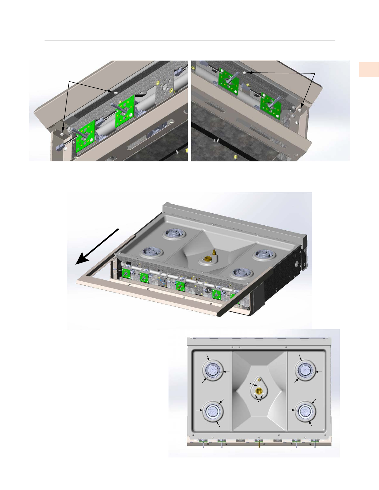
1. Remove the knobs, grates, burner caps and burner rings as shown below.
INSERT TOOL HERE
©2018 Hestan Commercial Corporation
3
EN
DISASSEMBLY
(continued)
4. Slide the bullnose trim assembly forward as shown and set aside.
3. Remove the screws shown below to detach the bullnose trim assembly.
REMOVE
2 SCREWS
LEFT SIDE RIGHT SIDE
REMOVE
2 SCREWS
SLIDE FORWARD
5. Remove all screws around each burner
base which hold the burner bowl in
place.
REMOVE ALL SCREWS
©2018 Hestan Commercial Corporation
4
EN
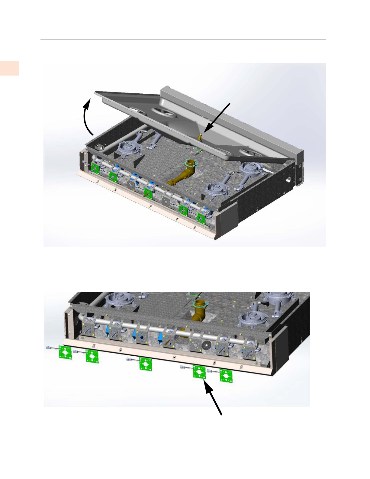
7. Remove each LED board from unit as shown below. You do not have to disconnect each wire
connector - they can be left hanging in place.
DISASSEMBLY
(continued)
6. Remove the burner bowl as shown below.
NOTE: CENTER BURNER IGNITER
WILL REMAIN ATTACHED TO BURNER
BOWL WHEN RAISED. DISCONNECT
THIS WIRE.
TILT UP BURNER BOWLABOUT
30 DEG. TO DETACH FROM REAR
ISLAND TRIM / RISER.
REMOVE LED BOARDS TO EXPOSE
VALVE ORIFICE ACCESS HOLES
©2018 Hestan Commercial Corporation
5
EN
ORIFICE LOCATIONS
8. Shown below is a typical burner layout. The dual-flow rear burners have 15500 BTU output, while
the dual-flow front burners are 23000 BTUs. The center single-flow burner (if equipped) has a 30000
BTU output (or 23000 on LP gas).
TYPICAL BURNER LAYOUT
(KRT365 SHOWN)
15.5k 15.5k
23k 23k
30k
The following pages describe how to replace the orifices in each burner type and each valve type. Do
one item at a time so as not to mix up orifices. All orifices must be fully seated and hand-tight to
reduce the chances of a gas leak. DO NOT USE any sealant, pipe dope, teflon tape, or anything else
on the orifice threads.
ABOUT HOSES: If you need to disconnect any hoses during this process, use caution to avoid
unnecessarily bending, twisting, or kinking any hoses. Hoses are stainless steel flex type which can
become brittle with age and can crack if handled roughly. Disconnect the fitting carefully where
necessary. You will perform a complete gas leakage test at the end of this procedure.

©2018 Hestan Commercial Corporation
6
EN
ORIFICE CHARTS
9. USE THIS CHART AS A GUIDE FOR REPLACING THE ORIFICES. SEE FOLLOWING PAGES FOR
REPLACEMENT INSTRUCTIONS FOR BURNERS AND VALVES.
NG LP NG LP NG LP NG LP NG LP
Front 23000 23000 046 055 073 078 065 073 080 087
Rear 15500 15500 052 058 073 078 065 073 080 087
Front 23000 23000 047 055 073 078 065 073 080 087
Rear 15500 15500 053 060 073 078 065 073 080 087
Front 23000 23000 049 056 074 079 065 073 080 087
Rear 15500 15500 054 062 074 079 065 073 080 087
H1
2000 - 5999 ft (600 - 1800m)
H2
6000 - 10000 ft (1800 - 3050m)
Sea Level - 1999 ft (600m)
BURNER
LOCATION
ALTITUDE
Dual Flow Burner
Main Orifice
023690-xxx
Dual Flow VALVE
Simmer Orifice
023701-xxx
Dual Flow Burner
Simmer Orifice
023698-xxx
Dual Flow VALVE
Low Orifice
023701-xxx
BURNER OUTPUT
(BTU/hr)

©2018 Hestan Commercial Corporation
7
EN
CHANGING BURNER ORIFICES
SIMMER ORIFICE
023698-XXX
MAIN ORIFICE
023690-XXX
.177 inch [4.5mm]
VENTURI /
AIR SHUTTER
THIS PORT TO
BE FULLY OPEN
DUAL-FLOW
BURNER BASE
ASSEMBLY NOTE: ALIGN VENTURI / SHUTTER WITH 2nd GROOVE.
DIMENSION SHOWN FOR REFERENCE ONLY.
LOCK
SCREW
10. The main BURNER orifice can be replaced without disconnecting the hose. The simmer orifice hose
must be disconnected to access the orifice inside. See the chart on pg. 6 to select the appropriate orifice
for your gas type / altitude. The part numbers and identification (color / stamp) for the orifice are given
in the tables above.
The detail view shows the appropriate venturi / air-shutter dimension. The dimension is shown for
reference only in case the lock screw was loosened, or the flame characteristics are not correct and need
adjustment. If adjustment is needed, loosen the lock screw and adjust the air shutter in or out in very
tiny increments, lock down the screw, replace all the components and check the flame again.

©2018 Hestan Commercial Corporation
8
EN
MAIN ORIFICE
(SEE P/N ABOVE)
AIR SHUTTER
SINGLE-FLOW
BURNER BASE
ASSEMBLY
X
LOCK
SCREW
ORIFICE
HOLDER
CHANGING BURNER ORIFICES
(continued)
11. The main BURNER orifice can be replaced without disconnecting the hose, however care must be
taken when handling to avoid bending or kinking the hose. Loosen the lock screw to extract the
orifice holder from the main body. See the chart on pg. 6 to select the appropriate orifice size for
your gas type / altitude. The part number and identification for the orifice is given in the table above.
When reinstalling the orifice holder in the body, be sure to set the correct air shutter distance
(Dimension X), then tighten the lock screw. If later on, the flame characteristics require adjustment,
loosen the lock screw and adjust the air shutter in or out in very tiny increments, lock down the
screw, replace all the components and check the flame again.

©2018 Hestan Commercial Corporation
9
EN
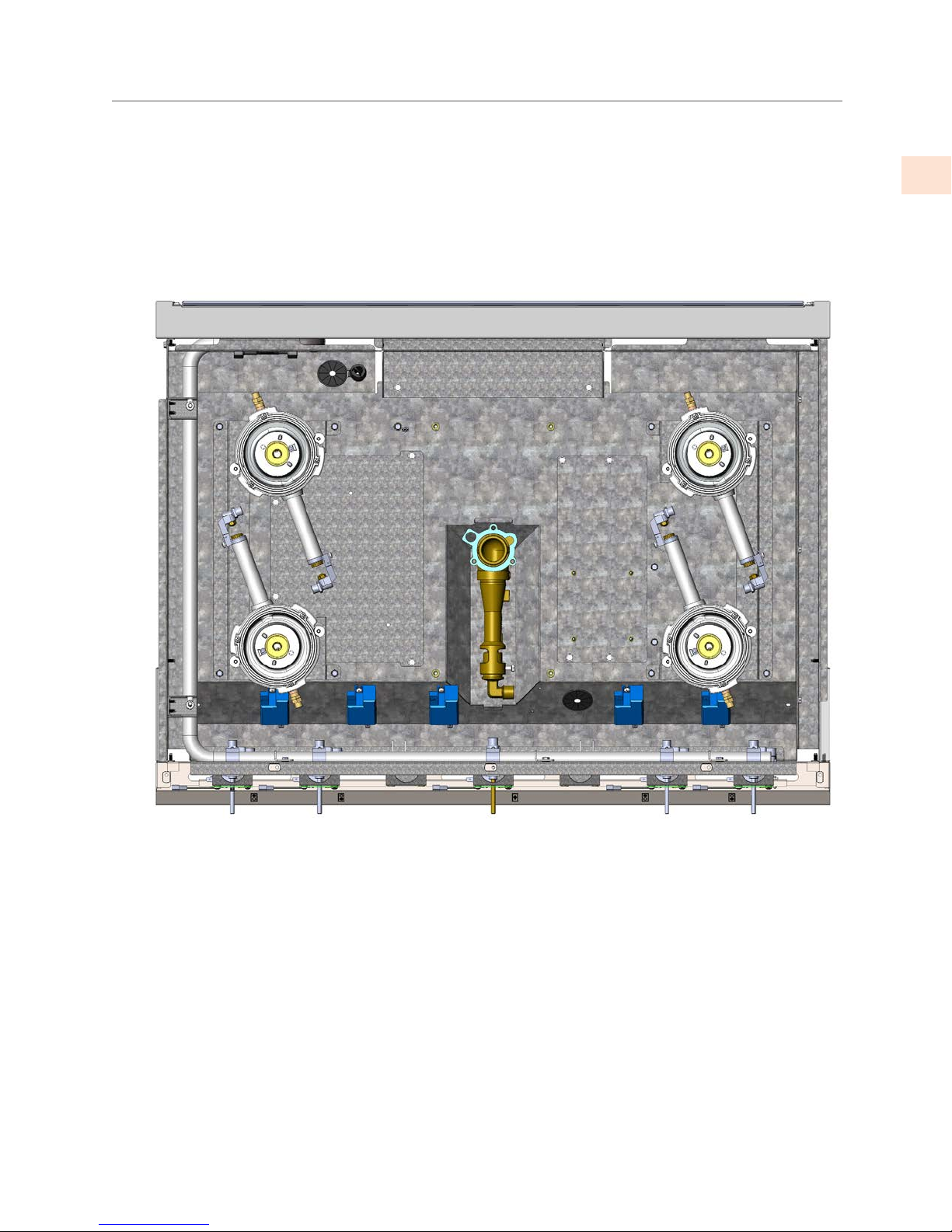
12. Remove the valve orifices via the access holes in the bracket as shown below.
ACCESSING VALVE ORIFICES
SINGLE-FLOW
VALVE DUAL-FLOW
VALVE
VALVE LOW
ORIFICE
VALVE
SIMMER
ORIFICE
VALVE LOW
ORIFICE

©2018 Hestan Commercial Corporation
10
EN
DUAL-FLOW
VALVE
NOTE: REMOVE AND REPLACE ONE ORIFICE
AT ATIME. MAKE SURE ORIFICE IS FULLY
TIGHTENED ON INSTALLATION.
VALVE LOW
ORIFICE
023701-XXX
VALVE SIMMER
ORIFICE
023701-XXX
CHANGING VALVE ORIFICES
13. Replace the VALVE orifices as shown below. See the chart on pg. 6 to select the appropriate orifice
size for your gas type / altitude. The part number and identification (color code) for the orifice is
given in the table below.
Table of contents
Other hestan Range manuals

hestan
hestan KRD485GDNGYW User manual

hestan
hestan KRD365-NG User manual

hestan
hestan KRG User manual

hestan
hestan KRD365LPYW User manual

hestan
hestan KRG485GD-LP User manual

hestan
hestan HFT Series User manual

hestan
hestan KRD304-LP User manual

hestan
hestan KRG365NGBU User manual

hestan
hestan KRD485GDNGWH User manual

hestan
hestan KRDS Series User manual


