Hestia H102 User manual
Wireless Monitoring System
v1.0
User Manual
Content
3.1 Features and Specifications
3.2 Overview
4.1 Powering and Battery Charging Monitor Unit
4.2 Powering Camera Unit
4.3 Mounting Camera Unit
4.4 Back Mount Mechanism
5.1 General Operation
5.1.1 Power ON/OFF
5.1.2 Icons Definition
5.1.3 Volume Adjustment
5.1.4 Brightness Adjustment
5.1.5 Switching Camera Number
5.1.6 Zoom
5.1.7 Video Off Mode
5.1.8 Intercom
5.1.9 Sound Level Indicator
1-2
3-4
5-6
7-10
11-19
5
6
7
9
10
8
11
11
12
12
13
12
13
13
13
13
14
15
5.3 Menu Mode - Video
5.2 Menu Mode
5.3.1 Color Saturation
5.3.2 Night Vision
5.3.3 Zoom Mode
15
15
15
2 Components List
3 Product Features and Overview
4 Getting Started
1 Safety Instructions and Warnings
5 Operation

5.4 Menu Mode - Audio
5.4.1 VOX Delay
5.4.2 VOX Sensitivity
5.4.3 Audio Alert
5.4.4 Sound Level LED
5.4.5 Auto Mute
5.4.6 Intercom Volume
5.5 Menu Mode - Camera
5.5.1 Camera Selection
5.5.2 Camera Pairing
5.5.3 Lullaby Playback
5.5.4 Auto Scan Mode
5.5.5 Split Screen Mode
5.6 Menu mode - Load Default
21-22
23
24
16
16
16
17
16
17
17
17
17
18
18
19
19
20
6
Troubleshooting and Tips
7 Warranty Information
8 FCC statement

Safety Instruction and Warnings
1
01
Strangulation Hazard - Keep the adapter cord out of the reach of
children. Never place the camera or cord within 3 feet (1 metre) of a
crib or playpen.
Cord Protection - Protect the adapter cord. Route cord so that
they are not walked on or pinched by items or against them.
Choking Hazard - This product contains small parts which may
cause choking. Not for children under 3 yrs.
Please read carefully this user manual before using Hestia H102
wireless monitoring system.
Wet and Moisture - Keep the monitoring system and all
accessories away from water such as a sink, bath tub, laundry tub,
swimming pool.
Heat and Fire - Keep all components away from heat source such
as fireplace, radiator, stove.
Ventilation - Provide proper ventilation for both monitor and
camera unit. Do NOT cover them with any material, such as a
blanket, cloth.
Cleaning - Disconnect all units before cleaning. Do NOT immerse
in water. Clean it only with a dry cloth.
Adapter and Battery - Use ONLY the AC adapters and battery
supplied with this product. Using other 3rd parties AC adapters or
battery may cause fatal damage to the product.

02
This product is intended for indoor use only.
This product is not a toy. Do NOT allow children to play with it.
When not using the product for long periods, remove the battery
and disconnect the A/C adapters from electrical outlet.
Please review product information before operation
Monitor: Product information is located at battery compartment
Camera: Product information is located at back side of camera
unit, after disassembled the camera stand
Do NOT attempt to open the monitor unit, camera unit, battery and
A/C adapter. No user-serviceable parts inside. Risk of electrical
shock, fire or death.
This product is not a substitute for responsible adult supervision.
Check your baby's activities at regular intervals.
Caution: Risk of explosion if battery is replaced by an incorrect
type. Dispose of used battery according to the instructions.
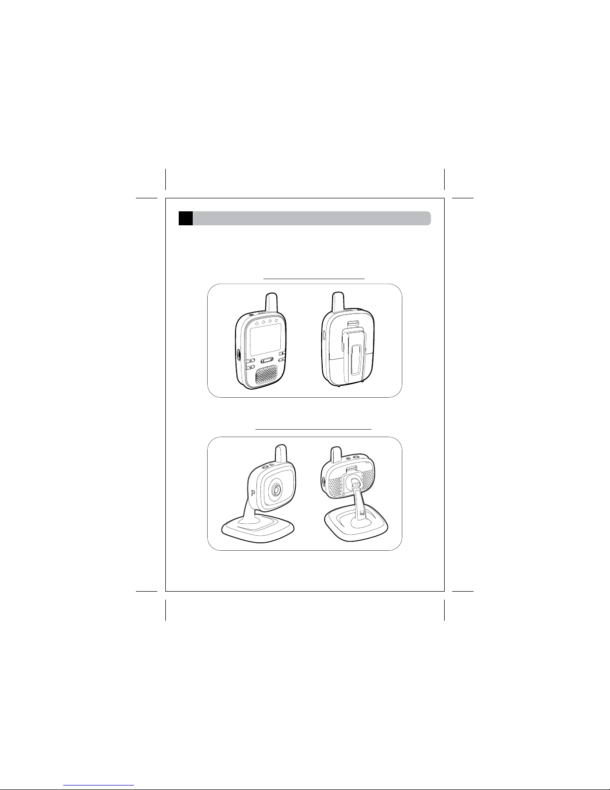
Component List
2
Monitor unit with flip stand
03
Thanks for purchasing Hestia H102 wireless monitoring system.
Please make sure you have the following components in the
packing.
Camera unit with camera stand
For combo kit, one more camera unit is bundled with H102
wireless monitor system.
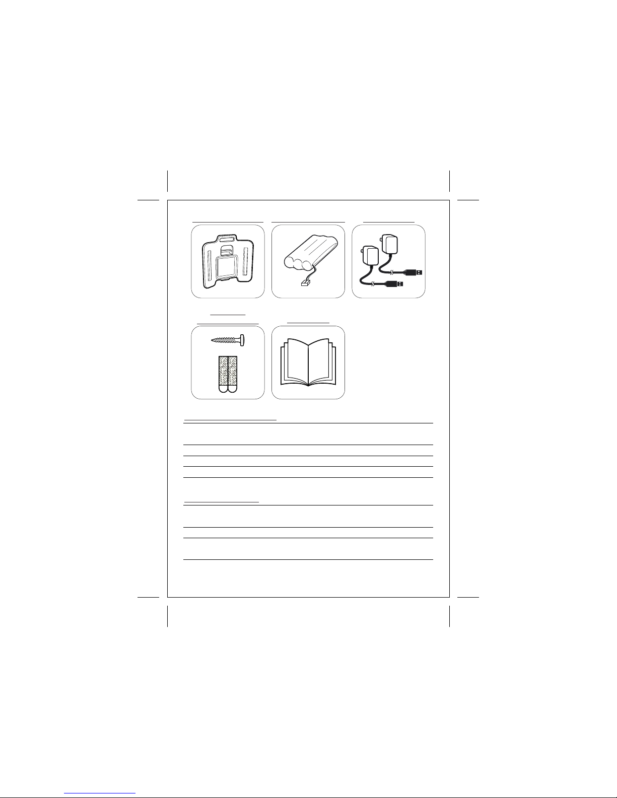
04
Multi-purpose Mount Rechargeable battery
Screw and
double-sided tape User Manual
AC adapters x2
5V 1A
Manufacturer Chou Sen Electronics
(Shenzhen) Co., Ltd. Kuantech Company Ltd.
Model number CS6D050100F series KSAS0050500100 series
Input 100-240V ~ 50/60Hz 1 00 -2 40 V ~ 50/6 0H z
Output
A/C Adapter Information
Manufacturer J&Y Technology Co.,
Ltd.
Shenzhen HighPower
Technology Co., Ltd.
Model number Ni-MHAAA850 3.6V HFR-AAA900x3(B)
Specification Ni-MH rechargeable
3.6V
Ni-MH rechargeable
3.6V
Battery Information
5V 1A
Product Features and Overview
3
3.1 Features and Specifications
Monitor unit
Indicator P ower (Blue)
Battery Charging (Red)
Control Power, Volume +/-, Brightness +/-, Menu </>,
Push to talk (PTT)
Audio 1W
Display 2.4" TFT color display at 320 x 240 resolution
Mounting Back mount compatible with flip stand
and multi-purpose accessories
Adapter 5 V 1 A , 100-240VAC @ 50/60Hz
Battery 3.6V NiMH AAA rechargeable battery
05
Ÿ Digital 2.4GHz (FHSS) Wireless Transmission.
Ÿ Extended transmission distance for greater than 300m in open area.
Ÿ Automatic night vision capabilities for operating in dim environment.
Ÿ Intercom (Push to talk) function allows dual way communication.
Ÿ Sound level indicator offers visible audio information during mute mode.
Ÿ 2x zoom function to provide high detail image.
Ÿ Video off mode (Audio only) for high efficiency power saving.
Ÿ Supports VOX (sound activation) and sensitivity setting available.
Ÿ Auto mute function to eliminate white noise during silence.
Ÿ 2 in 1 Split Screen and Auto Scan mode available for multiple cameras
monitoring.
Ÿ Remote control lullabies playback.
Ÿ Built-in Battery charger at monitor unit.
Ÿ Supports max. 4 camera units simultaneously.
Camera unit
LEDs Power (Blue)
Audio
1W
Lens F/1.8, EFL 2.95mm, FOV 61
CMOS 1/6.5" color CMOS
Sound Level Indicator(4 pcs)
LEDs Power (Blue)
Mounting B a c k mount compatible with camera stand
Indicator
Power(Blue)
Night Vision 8 x IR LEDs

3.2 Overview
Monitor Unit
Camera Unit
06
1
2
8
13
12
15
14
9
3
4
8
2
71
11
10 5
12 6
Power ON/OFF
Video off Button
Antenna
Power / Charging Indicator
Sound Level Indicator
TFT Display
Brightness + / -B utton
Menu / Button
Microphone
Speaker
Volume / Button
DC Jack
Strap Holder
Push to talk (PPT) Button
Flip Stand
Battery Door
1.
2.
3.
4.
5.
6.
7.
8.
9.
10.
11.
12.
13.
14.
15.
Light Sensor
Antenna
Power ON/OFF Button
Lens
Microphone
Pairing Switch
Speaker
Power Indicator
DC Jack
Tripod Socket
Camera Stand
Cable Mount
1.
2.
3.
4.
5.
6.
7.
8.
9.
10.
11.
12.
3
6
7
9
10
11
5
4
Getting Started
4
4.1 Powering and battery charging Monitor Unit
07
pic.1
pic.3
pic.2
Bla ck
Red
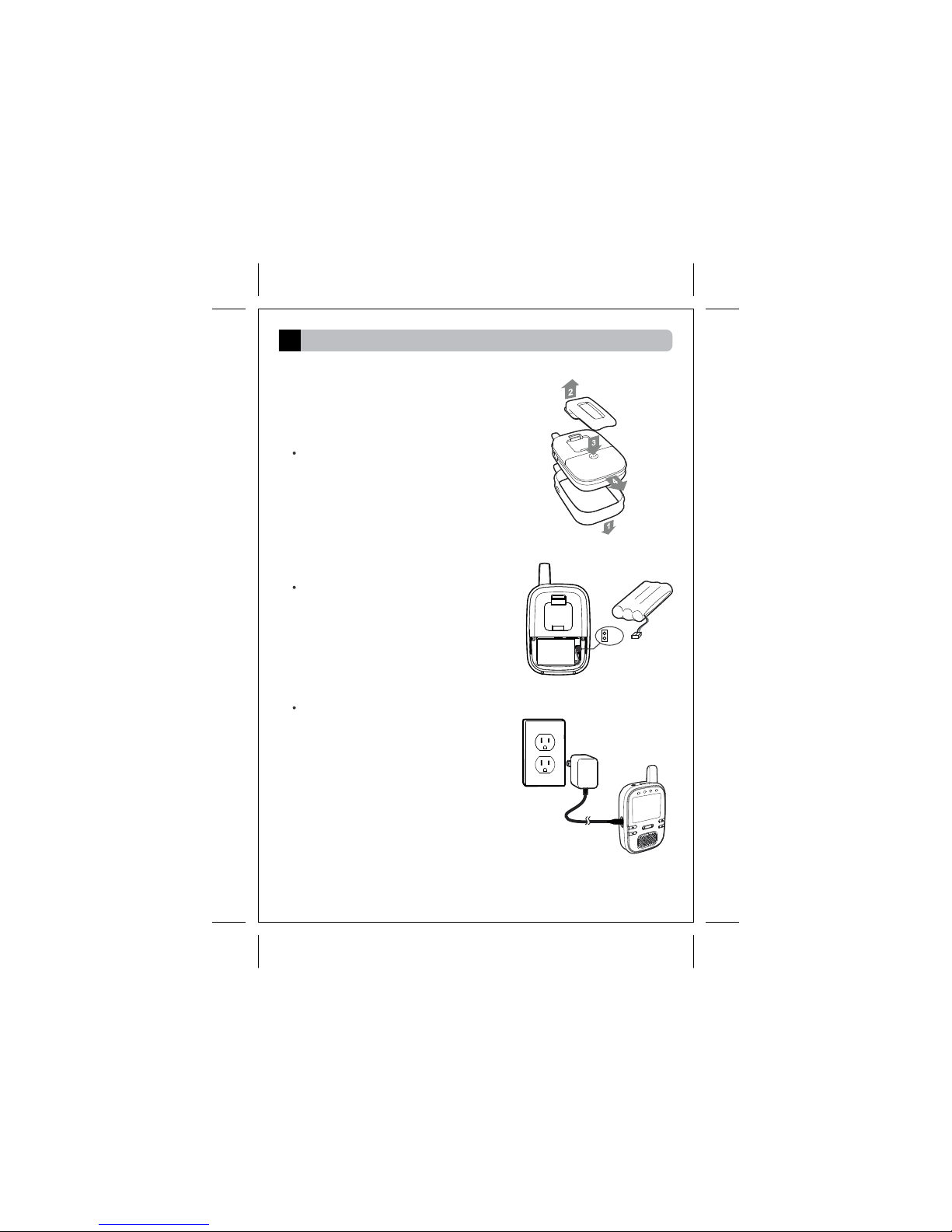
As shown in pic. 1, remove the silicon
sleeve and flip stand from monitor
unit. Then open the battery door.
Insert the rechargeable battery to
the battery bay and plug into the
battery socket as instructed in pic. 2.
Close the battery door, install the
silicon sleeve.
Plug the A/C adapter into the wall
electrical outlet. Then attach the cord
to the DC Jack as shown in pic. 3.
The battery charging process will be
started automatically (Red Indicator
on).
For first time usage, please keep
charging the battery for at least 8
hours until the red Indicator goes off.

4.2 Powering Camera Unit
08
pic.4
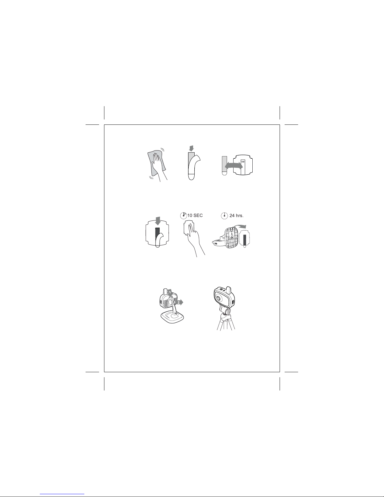
4.3 Mounting Camera unit
The camera unit was designed to
s u p p o r t d i f f e r ent mo u n t i n g
mechanism, from simply putting
on a table to mounting on a wall
by screw or double-sided tape.
1. Tighten the provided screw
the
provided screw onto the wall
surface by a screw driver, until
the screw only sticks out by
about 6mm as shown in pic. 5.
2. Remove the base plate from
camera stand, and hook the
camera stand onto the screw.
Mount the camera unit by screw
pic.5
6mm
Plug the A/C adapter into the
wa ll el ectrica l o ut let. Then
attach the cord to the DC Jack as
shown in pic. 4.
09
Mount the camera unit by double-sided tape
pic.6
Blac k Word
pic.7
1. Clean the mounting surface by alcohol.
2. Remove the cover label from the double-sided tape, and stick it onto
the recess area of camera base plate, as s hown in pic. 6
3. Remove the cover label from the other side of double-sided
tape, and stick the camera base plate onto the mounting surface.
Press the camera base plate onto the mounting surface for 10
seconds. Wait 24 hours then hook the camera stand onto base plate.
Mount the camera by tripod
1. Remove the camera stand as shown in pic. 7.
2. Fasten the tripod (not included) to the tripod mount at the bottom of
camera unit.
10
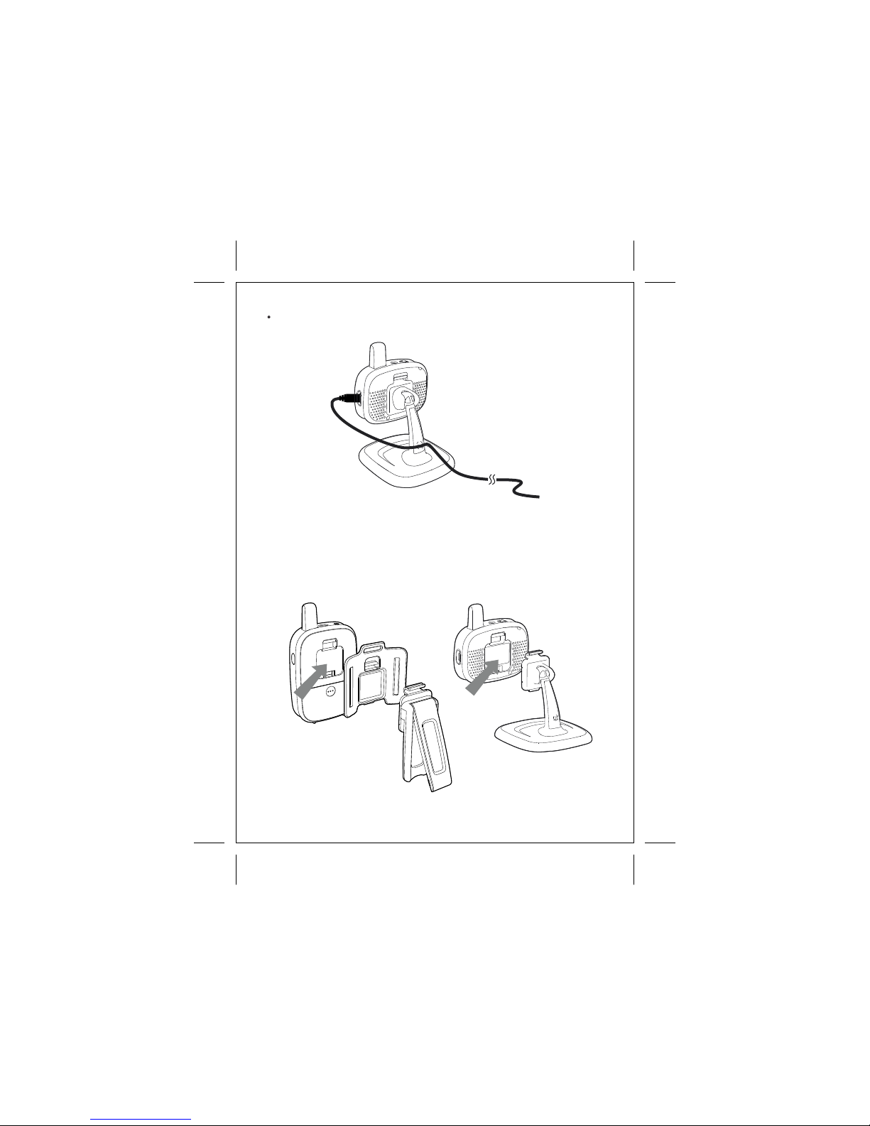
Power cord cable can be inserted to the cable mounted as shown in pic. 8.
Both monitor and camera unit carried an identical back mount
mechanism. Different accessories (flip stand, multi-purpose
mount, camera stand) can be installed to either monitor unit or
camera unit based on different needs.
4.4 Back Mount Mechanism
11
Operation
5
5.1 General Operation
User operation is divided into 2 different modes. General
operation is referring to user operations when the capturing
image being displayed on screen.
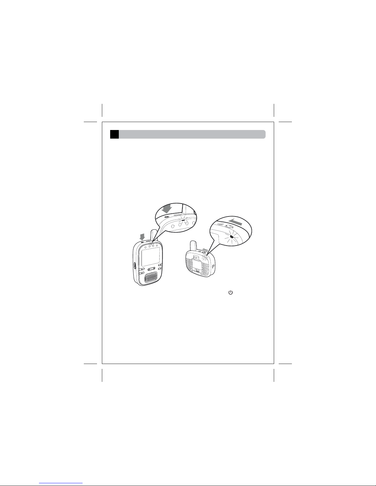
5.1.1 Power ON/OFF
To power on Monitor unit, press the power button and hold for
1 second. The Power LED will emit blue light to indicate the
system is on.
To power on Camera unit, slide the power switch to the 'ON'
position. The Power LED will emit blue light to indicate the
system is on.
12
Volume / Brightness
Level
Camera Number
Signal Reception
Battery Capacity
Volume / Brightness
Level
Brightness level control
Volume level control
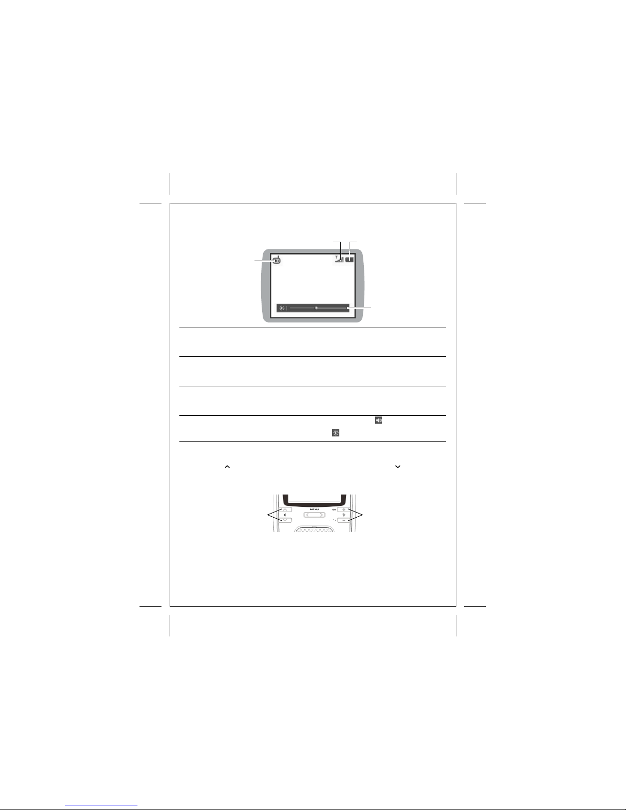
5.1.2 Icons Definition
Camera number
Indicates the current camera shown on screen.
The camera number will be displayed at numeric
form inside the icon.
Indicates the current signal reception strength
from camera unit. During no signal status, a
flashing icon will be shown.
Indicates the capacity of NiMH battery. During
battery charging, a color changing icon will be
shown.
Indicates the current volume
and brightness Level
5.1.3 Volume adjustment
5.1.4 Brightness adjustment
Signal Reception Battery Capacity
Press '+' button to increase the brightness level. Press '-' button to
decrease the brightness level. Once the brightness level is changed,
there will be a level bar shown on screen to display the current level.
Press ' ' button to increase the volume level. Press ' ' button to
decrease the volume level. Once the volume level is changed, there
will be a level bar shown on screen to display the current level.
13
5.1.5 Switching Camera number
Tips
5.1.7 Video Off mode
Video off mode is for saving power purpose by shutting down the
screen of monitor unit manually. The wireless transmission and audio
system will remain to operate during video off mode. To enable the
video off operation, press the power button once. Press any button
of monitor unit will exit video off mode immediately.
5.1.8 Intercom
Intercom (two-way talk) can be activated by press and hold PTT (Push
to talk) button. Upon activation, voice signal will be transmitted from
microphone of monitor unit to camera unit. While intercom is activated,
an icon will be displayed next to the camera icon, and sound level
indicator will be temporarily disabled. Release the PTT button will
deactive the intercom function.
Intercom volume level can be adjusted, as mentioned in section
5.4.6
Tips
5.1.9 Sound Level Indicator
Sound Level Indicator are the 4 LEDs located at top of the display
screen. It provides a visualized sound level captured from camera
unit. The higher the sound level captured, the more LEDs will be
lighted up.
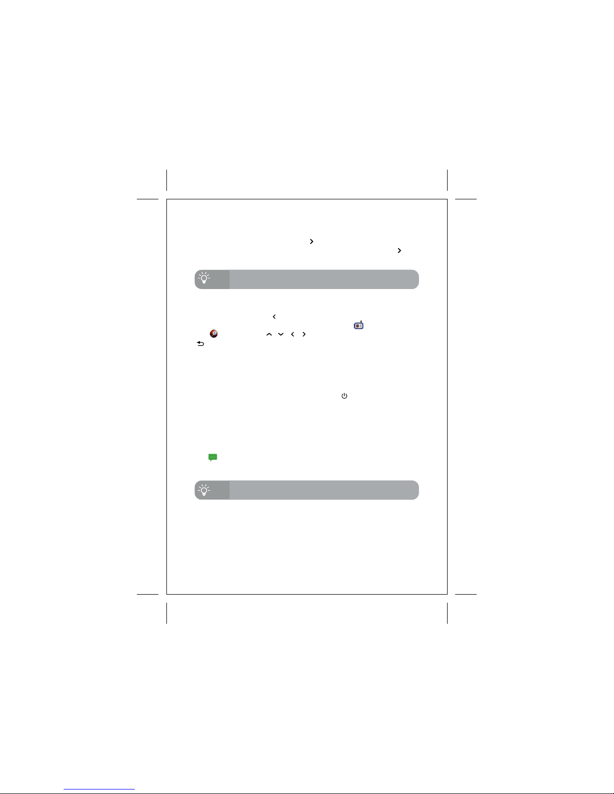
5.1.6 Zoom
, , ,
Hot-keys is available for activating zoom function at general operation.
Press and hold menu button for 2 seconds will activate the zoom
function. During zoom mode, the camera icon will be replaced by
ball icon. Press to move the zoom window. Press
button to exit zoom mode.
Switching camera function is also available at menu mode, as
mentioned in section 5.5.1
Hot-keys is available for switching different camera number at general
operation. Press and hold menu button, then press + button will
switch to next camera number. Press and hold the menu button,
then press - button will switch to previous camera number.

14
Title
Function / Options
Description
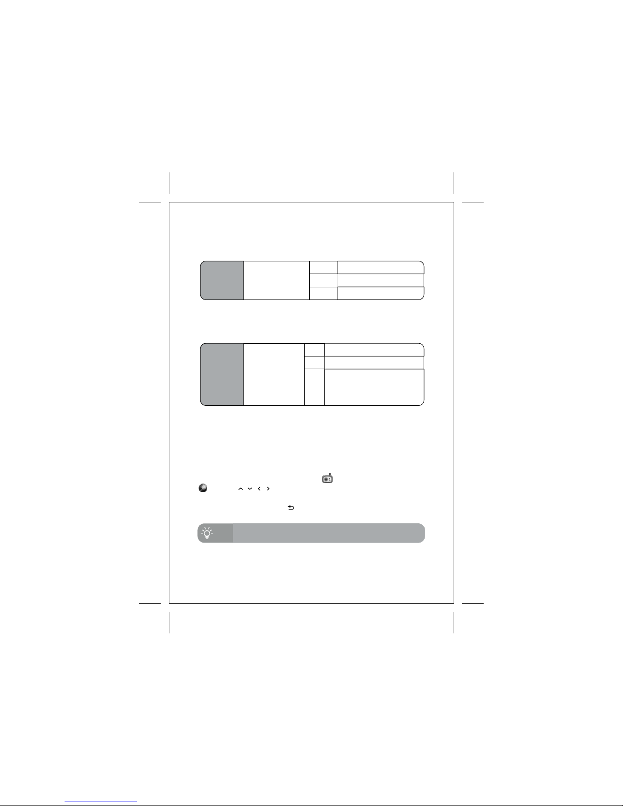
5.2 Menu Mode
4 main titles are available - Video, Audio,
Camera and Defaults.
At different title, different functions and their
current settings will be shown.
S h ow a b r i e f d e s cr i p t i o n o f s e l e c t ed
components.
Menu mode can be activated by pressing either menu button or
menu once. The below screen will be displayed during menu mode.
Title
Function / Options
Description
Video Settings Audio Settings
Camera Settings Load Defaults
To select different title, press or button until the cursor reaches Title
column and highlighted. Press menu or menu button to select
different title.
To select different function, press or button until the cursor reaches
desired function column and highlighted. To change the option, press menu
or menu to select different available options. Selected setting will be
effective immediately. In some functions, it required to go to next page for
more settings, as below screen. Upon selected, there will be a '…'
displayed behind the function name, press 'OK' button to go to next page
for further settings.
To exit menu mode, press / button.
15
5.3 Menu Mode - Video
Saturation
Adjust the color
saturation of
displayed images
Vivid
Normal
Cool
High saturated image
Normal saturation
Low saturated image
5.3.1 Saturation
Night Vision Select different
Night vision mode
ON
OFF
Auto
Set ON the Night Vision mode
Set OFF the Night Vision mode
Use build-in light sensor to
detect light level and trigger
ON/OFF the night vision mode
automatically
5.3.2 Night Vision
5.3.3 Zoom mode
To enter zoom mode, select '<ENTER>' option and press 'OK' button. It
will exit menu mode and show the capturing image with zoom mode
activated.
During zoom mode, the camera icon will be replaced by ball icon
.Press button to move the capturing area.
, , ,
To leave zoom mode, press button.
Zoom function is also available at primary screen of split
screen mode.
Tips

16
5.4 Menu Mode - Audio
VOX Delay
Duration of silent
before entering
VOX mode
30
seconds
60
seconds
5.4.1 VOX Delay
VOX is a power saving feature to turn off video and audio system of
monitor unit, when the environment of camera side is silent. The
system will be resumed automatically when camera unit detect noise.
There are two user settings available for VOX function. VOX Delay is
referred to the duration of silence before entering VOX mode.
VOX set OFF
OFF
VOX set ON and enter VOX mode
after 30 seconds silence
3
minutes
VOX set ON and enter VOX mode
after 60 seconds silence
VOX set ON and enter VOX mode
after 3 minutes silence
5.4.2 VOX Sensitivity
VOX
Sensitivity
Adjust the
sensitivity
of camera
microphone
at VOX mode
High
Medium
Require less sound level to trigger
VOX mode. For quiet environment.
Low
Require standard sound level to
trigger VOX mode.
Require high sound level to trigger
VOX mode. For noisy environment.
5.4.3 Audio Alert
The function of Audio Alert requires to go to new menu page for setting
purpose. Press 'OK' at Audio Alert column will go to the new page.
Low Battery
Enable audio alert when battery is at low capacity
Disable audio alert when battery is at low capacity
Out of Range
OFF
ON
OFF
ON
Enable audio alert when no signal reception from
camera unit
Disable audio alert when no signal reception from
camera unit
VOX Sensitivity is referring to the sound level detected by camera unit
to be regarded as silence.
17
5.4.4 Sound Level Indicator
Sound Level indicator is the 4 indicators located at top of display
screen, showing the sound level captured from camera unit. Set ON to
activate this function, set OFF to disable the indicators.
5.4.5 Auto Mute
Auto Mute function acts as a white noise eliminator, which shut down
the audio system when no sound is captured from camera unit for 10
seconds. When Auto Mute is activated, and noise is detected from
camera unit, the audio system of monitor unit will be resumed. Set ON
to activate Auto Mute function. Set OFF to disable Auto Mute function,
and audio system will operate all the time.
5.4.6 Intercom Volume
Intercom Volume is to adjust the speaker volume of camera unit. 5
levels are available. Press menu to increase the volume level, press
menu to decrease the volume level.
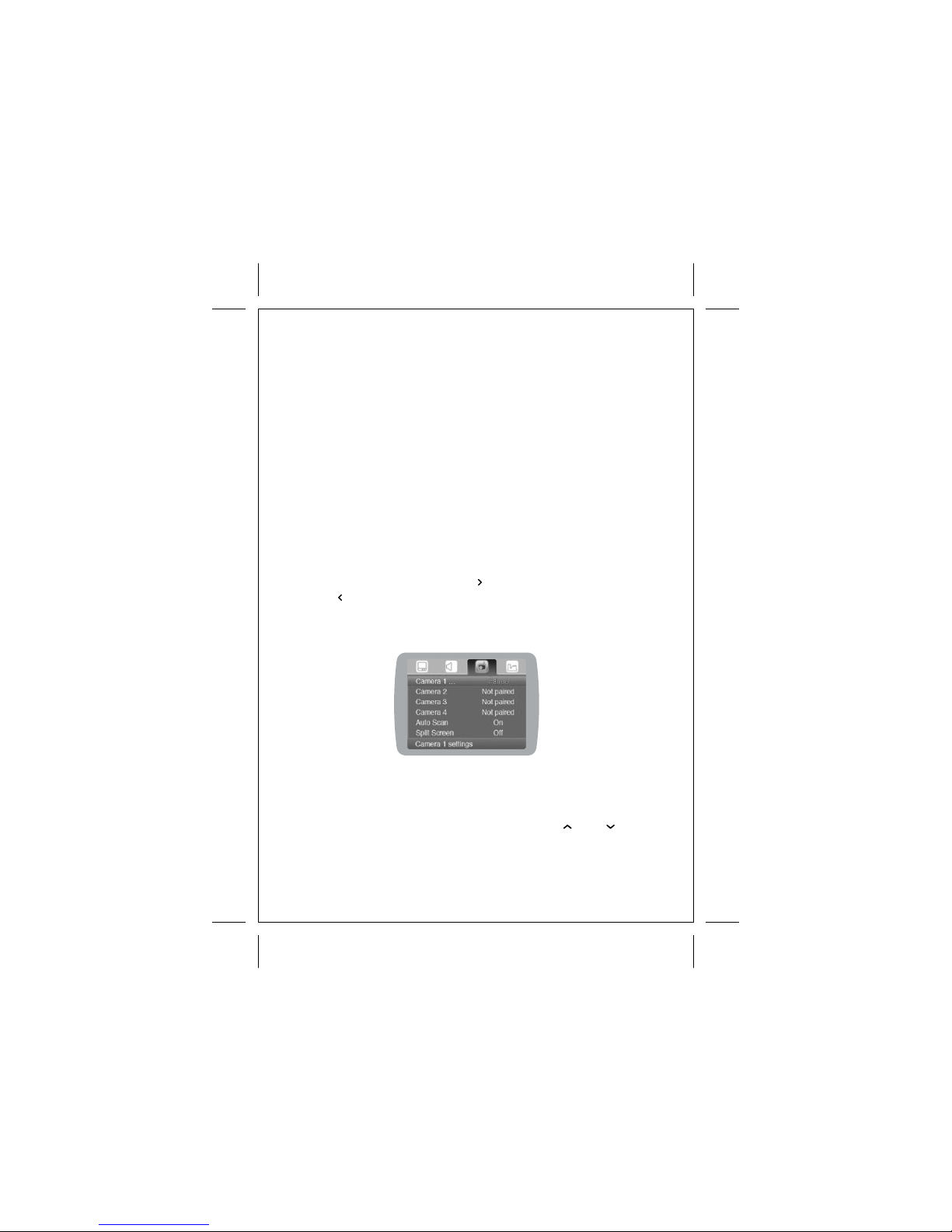
5.5 Menu Mode - Camera
The monitor unit is capable to pair with 4 camera units, as shown below :
5.5.1 Camera Selection
The camera number labelled as 'Paired', indicates a camera unit is
currently registered. The camera number labelled as 'Not paired'
indicates no camera unit is registered. Press or to select
different camera. Press 'OK' button will go to next page for setting
purpose.
Table of contents
Other Hestia Baby Monitor manuals


