Heusinkveld Sim Handbrake User manual

1
Sim Handbrake
product manual
version 1.0

2
Congratulations on acquiring a Heusinkveld
Sim Handbrake! We hope you will enjoy this
top-of-the-line racing simulator product for
many years to come.

3
Packing list
The box contains the following:
• Handbrake
• Adapter plate
Accessory box, which contains:
• USB cable
• Hex key tool
• Elastomer springs
• Mounting materials
• Manual
Digital download
The current version number of this manual is listed
on the cover of this document. The latest version of
the manual can be downloaded at Heusinkveld.com/
support
Contact
If you have any questions which are not covered
in this manual, feel free to send us an email at
suppor[email protected].
Table of contents
This manual has the following main sections:
• Introduction
• Initial setup
• Mechanical adjustments
• Smartcontrol adjustments
• Maintenance
This is the manual for the Heusinkveld
Sim Handbrake. We advise you to read
it thoroughly in order to get the most
enjoyment out of your handbrake.
Introduction

4
Initial setup
In this section we’ll explain how to mount
the handbrake to your rig and make fine
adjustments to the setup.
Mounting materials
A selection of bolts, nuts and T-nuts is included
with your handbrake. These will in many cases be
sufficient to create a solid mount between your
simulator, the handbrake and the optional adapter
plate.
Please note that there is a great variety of simulator
platforms available and we cannot foresee every
possible mounting scenario. We can therefore not
rule out that you may need to source some mounting
materials yourself.
Overall position of the handbrake
Before starting the installation, determine the overall
position of the handbrake which works best on your
simulator. Take the following into account:
• The base can be mounted in a horizontal or
vertical position.
• The lever can be mounted in a horizontal or
vertical position (relative to the base).
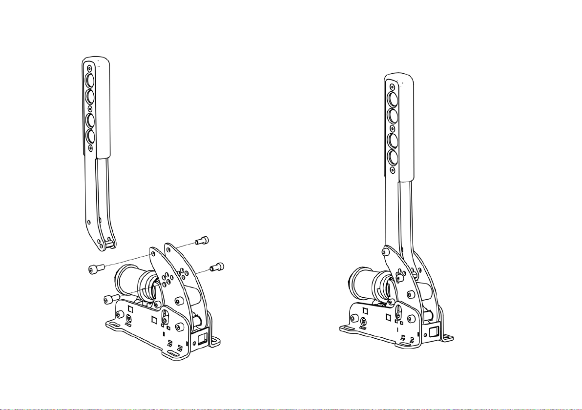
Changing the orientation of the lever
By default the lever is in a horizontal position. The
lever can be reassembled to a vertical position
relative to the base of the handbrake.

5

6
Mounting the handbrake to your simulator
If you have determined the general position of the
handbrake, you can decide on how to mount the
handbrake to the simulator. There are 2 options for
mounting the handbrake to your simulator:
1) Using the 4 holes on each corner of the base to
mount the handbrake directly to your simulator.
2) Using the adapter plate as a mounting platform
between the handbrake and your simulator.
The adapter plate can be mounted with 2 bolts and
t-nuts to an aluminium profile. The 4 holes on each
corner of the handbrake match the pre-tapped corner
holes of the adapter plate. No nuts are needed here.

7
Yaw adjustment on the adapter plate
The adapter plate has a 22,5 degrees yaw adjustment.
Adjust the yaw of the handbrake by choosing different holes to bolt the adapter plate to your simulator.

8
Fine-tuning the position of the lever
There is also an option to fine-tune the angle of the
lever. In the vertical position you have 26 degrees
of freedom. In the horizontal position you have 19,5
degrees of freedom (the lowest position can’t be used
when the lever is horizontal).
In order to fine tune the position of the lever, adjust the
position of the lever mounting bolt closest to the base.

9
Connecting the electronics
We’ve provided a USB-cable with the handbrake.
The controller board of the handbrake is integrated
inside the base. One side of the USB-cable can be
plugged into the handbrake. The other side should be
connected directly to your pc.
Please make sure there is always a bit of slack in the
cable. This prevents damage to the plug, socket and
electronics. Specifically if you use a motion simulator,
secure the USB cable to the (moving) frame of your
simulator before you connect it to your handbrake.
Plug and play
Your handbrake is now ready for racing. It is pre-
calibrated with a force of approximately 15 kg and it
will work after assigning it in your favorite simulator
software. Please note that iRacing requires an
additional one-time in-game calibration: calibrate the
handbrake to an output of 4095.

10
start as soon as you compress the metal coil spring,
or only after the metal coil spring has been fully
compressed.
The following adjustments are available:
• Resistance of the main elastomers (overall
resistance).
• Travel on the metal coil spring.
• Preload on the metal coil spring.
Adjusting the overall resistance
Your handbrake has been supplied with 3 elastomers.
One is already installed in the spring stack, the
other 2 are in the accessory box. By changing the
elastomer you can change the overall resistance of
the handbrake.
Mechanical
adjustments
The Sim Handbrake offers plenty of
mechanical adjustments which change the
mechanical feel of the handbrake.
Principle of operation
Your Sim Handbrake is force based. The harder you
pull, the higher the signal output to the simulator
software will be.
The handbrake has a spring stack with a 2-stage
system. Initially a metal coil spring is compressed.
This coil spring simulates the pad-to-disc gap and/or
the slack on the handbrake cable. The main loading
of the brake disc is simulated by compressing the
elastomers.
By adjusting the handbrake deadzone in SmartControl
you have the option to let the brake signal output

11
28 mm soft rubber (softest option)
28 mm hard rubber (default)
19 mm hard rubber (hardest option)

12
The top stack has the lowest resistance. The bottom
stack has the highest resistance. By default your
handbrake is set up with a medium resistance.
A small wrench is supplied with your handbrake to
remove the end-cap of the stack. The required parts
to build any of the above stacks are included with
your handbrake.
Please note that changing the elastomer does
not change the amount of force required to reach
maximum output on the handbrake. The required
amount of force can be changed through the
SmartControl software.

13
Removing the metal coil spring
If you don’t want to to use the metal coil spring, you
have the option to remove it completely.
Adjusting the preload on the spring stack
You can change the preload on the spring stack using
the knurled knob. Always make sure the end-cap sits
against the knurled knob after adjusting.
By increasing the preload, you need a higher initial
force to get movement in the lever. As a side effect
the spring stack (mainly the metal coil spring) will
compress a bit, resulting in a slightly lower travel.
Adjusting the travel on the metal coil spring
Your Sim Handbrake is fitted with a metal coil spring.
This metal coil spring simulates typical handbrake
system slack. This slack may exist in a system where
a brake pad is moved by hydraulics and needs to grip
on a disc, or from slack in a cable based system.
The amount of travel in this metal coil spring can be
varied by changing the length of the spacers inside
the metal coil spring. At minimum the 10mm spacer
should be present inside the spring. In order to
shorten the travel, you can add 1-3 additional small
spacers.

14
Settings applied in SmartControl will have effect
in any simulator software, without having to
make additional adjustments, re-assign controls
or recalibrate (including iRacing) in the simulator
software itself.
Calibration
SmartControl also includes a calibration wizard.
Because your handbrake has been pre-calibrated
during assembly, calibration is not required
before first use. Recalibration in SmartControl is
only required when you have made mechanical
adjustments to the spring stack.
Boom deadzone adjustment
You can set a bottom deadzone for the handbrake
in SmartControl. If you increase the deadzone, the
handbrake lever requires a bit of force/movement
Smartcontrol
Adjustments
Your Sim Handbrake comes with a
powerful configuration tool allowing to set
up your handbrake in ways not previously
possible: SmartControl.
Download SmartControl
The software can be downloaded from our website
heusinkveld.com. Click on Support (top bar). Scroll
to Sim Handbrake. Click on Download SmartControl.
Save the file and run from a folder of your choice.
Overview
With SmartControl you can configure (non-linear)
handbrake output curves, set pedal deadzones and
the brake pedal force. All settings can be saved into
profiles, which can be loaded again in a few mouse
clicks.

15
Handbrake output mapping
A key feature of SmartControl is the ability to set
a custom signal output map for your handbrake.
Traditionally race simulator controller output has had
a one-on-one sensitivity in relation to the handbrake
input. SmartControl allows you to map non-linear
output curves using 5 zones (six input parameters).
The handbrake has a Curve Type pull-down menu
with pre-defined output curves. Here you can also
select the option to make a custom curve and then
set the desired pedal output percentage at the 0%,
20%, 40%, 60%, 80% and 100% marks of the pedal
input. You have complete freedom to set your own
shapes.
Please note that some simulator software offers in-
game options affecting the linearity of certain pedal
outputs. In order for SmartControl to work effectively,
always make sure that all in-game settings are set
linear.
We will illustrate this functionality with a few use
cases on the next pages:
before it registers output. The effect of your deadzone
setting can be checked in realtime in the green
vertical signal output bar.
Handbrake force seing
SmartControl allows you to set a maximum force on
the handbrake. This setting is in kilograms (kg) and
represents the actual force pulled on the handbrake
lever. The maximum brake force is 22kg. When you
pull the maximum force on the handbrake, the
handbrake will give 100% brake output signal to the
simulator software.
Depending on which elastomers are installed in the
rubber stack, you may reach the end-stop of the
handbrake before reaching the maximum handbrake
force. We strongly recommend setting a maximum
handbrake force which can be achieved without
having to pull the lever into the end-stop.
How you set the maximum handbrake force further
depends on your personal preference. Even in similar
real race cars, the required handbrake force varies a
lot as this is a function of the specific components
installed in that car.

16
Use case 2: Handbrake curve on a high grip surface.
Rear wheels tend to lock up later on a high grip surface
such as tarmac (for example at 80% handbrake output).
By setting a concave output curve you can more easily
reach full rear wheel lock, which may help you to better
navigate hairpins on tarmac.
Use case 1: Handbrake curve on a low grip surface.
Rear wheels tend to lock up earlier on low a low grip
surface such as gravel (for example at 50% handbrake
output). By setting a convex output curve you can
increase the useful range of the handbrake. You’ll now
effectively have a broader range for fine modulation
before it reaches 50% output and the wheels are fully
locked.

17
Use case 3: Immediate lock for driing
In drifting competitions instant lock of the rear
wheels may be required. By setting a very aggressive
output curve, instant lock can be achieved at even
the slightest pull at the handbrake lever.

18
This ensures that your SmartControl settings always
function correctly in iRacing. You will only need
to calibrate in iRacing once. Re-calibration after
changing SmartControl settings is not required.
iRacing offers the optional setting ‘custom controls
for this car’. If you use this setting, always make sure
to follow the instructions 1 and 2 per car in order
for your SmartControl adjustments to function
correctly in iRacing.
Save and Load profiles
SmartControl allows you to store an unlimited
amount of profiles. In order to save a profile, click on
File and then Save Profile. In order to load a profile,
click on File and then Load Profile.
Using SmartControl with iRacing
The Sim Handbrake sensor output value always
ranges from 0-4095, regardless of your settings in
SmartControl. Most simulator software can instantly
use these output values, because Windows works
with a default range of 0-4095 for 12bit USB devices
as well.
A notable exception is iRacing, because iRacing uses
an in-game method to calibrate the handbrake. In
order for the Sim Handbrake to function correctly in
iRacing, you must do the following:
When using the handbrake calibration wizard in
iRacing, you will see a RAW value. When asked to
pull the handbrake, make sure you always pull it to a
value of 4095.

19
Shared profiles with other SmartControl
compatible products
If you have other Heusinkveld products which work
with SmartControl, you can create shared profiles for
multiple devices (for example a profile which includes
settings for a handbrake + pedal set).
When loading a profile you have the option to load
specific elements of a shared profile (for example
only load the profile settings of the handbrake and
not for the pedals).
Good to know
All profiles are saved relative to your personal
calibration values. This means that you can exchange
profiles with fellow Sim Handbrake owners and apply
them without re-calibrating.
Profile changes are applied directly onto the Sim
Handbrake controller board. If your simulator
software is Alt-TAB friendly, you can apply a different
profile or test specific adjustments in the middle of a
training session.

20
Recommended lubricant
If you do feel the need to lubricate parts of your
handbrake, the recommended lubricant is PTFE Dry
Spray. Under normal circumstances this should not
be necessary.
Support
If you need any help, please send us an email at
suppor[email protected].
Maintenance
Your Sim Handbrake has been designed to
have a minimum of wear, tear and noise.
Please take note of the following in order
to keep your product in good shape for
many years.
Preventive maintenance
The Sim Handbrake has been designed to not require
any preventive maintenance. All pivot points contain
self-lubricating bearings and the elastomers have
minimal friction relative to other parts of the spring
stack.
Elastomers
After very prolonged use (tens of thousands of duty
cycles) the elastomers may leave a small amount of
dust-like residue. This can safely be wiped away with
a dry cloth. The performance of the elastomers will
not be affected: These have been tested to retain
their as-new characteristics even after one million
duty cycles in an overload situation.
Other Heusinkveld Music Pedal manuals
Popular Music Pedal manuals by other brands

Dunlop
Dunlop AKIRA TAKASAKI CRY BABY FUZZ WAH manual

Sony
Sony DME-3000 Product guide

Radial Engineering
Radial Engineering Bones Holywood owner's manual

TC Electronic
TC Electronic DITTO X2 LOOPER Service note

Becos
Becos CIQ-1 COMPIQ MINI ONE PRO manual

TC Electronic
TC Electronic Vintage DISTORTION user manual