Hewalex ZPS 18e-01 ECO User manual
min. 20 cm
Hydraulic brake
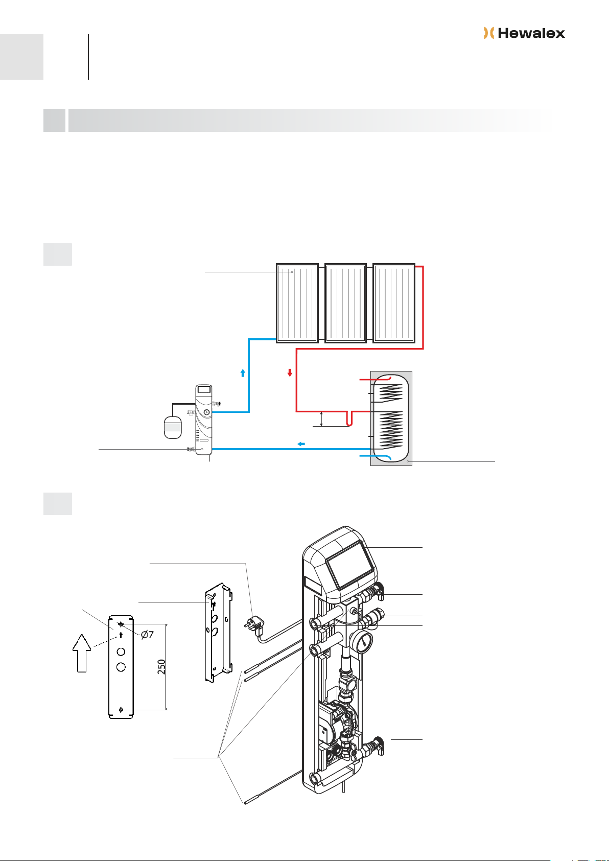
The ZPS pump and control unit is designed to work with solar collectors in systems with required flow of the heat transfer fluid up to 18 l/min,
depending on the surface of the mounted solar collectors.
The ZPS pump and control unit is compacted in a foamed polypropylene cover and it contains accessories necessary for correct functioning of the
solar installation: solar circulation pump, air separator, discharge valves, check valve, shut-off valve, manometer, electronic flow meter, G-422
controller with four temperature sensors and power cable.
T2
T1
ZPS 18e-01 ECO
ZPS 18e-01 ECO
Safety valve 6bar + EPDM gasket
Discharage valve + EPDM gasket
Discharge valve + EPDM gasket
Assembly support
T4
* Power cable 230 V and cables for temperature sensors
have the possibility to exit into the left or right side
Temperature sensor NTC10kW*
Power cable 230V
Distance between the holes
T3
Plug KS 3/4 + EPDM gasket
1
1
Assembly instructions for the pump and control
unit ZPS 18e-01 ECO
USE AND CONSTRUCTION OF THE PUMP AND CONTROL UNIT ZPS 18E-01
Diagrams and assembly drawings
water heater
11.01.2023
solar collectors
Fig. 1.
Fig. 2.
EN HEWALEX Sp. z o.o. Sp. k.
+48 32 214 17 10
www.hewalex.pl

Attach the support of the ZPS unit to the wall using 2 anchor screws (fig. 2).
Hang the ZPS pump and control unit on the assembly support previously installed.
The pump and control unit should be installed with the lower discharge valve at the bottom level of the solar coil exit in the heater. This
connection allows to empty in correct way the solar fluid from entire system if necessary. Both right-hand and left-hand mounting is allowed.
Do not use additional shut-off valves between the solar coil, pump unit and piping of the installation. Any elements, other than supplied by the
manufacturer, can be the cause of problems and the occurrence of leaks. Use the distance bracket (fig. 3) for the installation of the pump and
control unit on the wall where the pipes are previously installed. This bracket not constitutes an accessories delivered normally with the
ZPS18e-01 ECO.
Connect the hydraulic connections of the ZPS pump and control unit with the other devices of the solar system according to the schematic
diagram of the system (fig. 1) and the drawing 4.
Place the temperature sensors in the right places in the system according to the schematic diagram (fig. 1). For proper temperature read-out
and operation of the installation, slide in temperature sensors all the way into the sleeves.
For proper operation of the system should be properly insulate and secure the connection of the temperature sensor T1. You should solder
wires and hermetically secure the shrink tube. If the installation pipe does not have an intergrated cable, extend the wire. Heat shrink shrinks
by the heat, because the application of it to cables must be evenly heated air at 70°C - 80°C. It is not allowed to inaccurate weld heat shrink and
leaving blisters the air in the sealed casing. Moisture, rust contacts causes a false temperature reading and abnormal operation of the
controller.
The system should be filled with a heat transfer fluid, which is a water solution of propylene glycol, with a crystallization temperature –25°C with
an addition of an inhibitors protecting the system against the corrosion.
Attention!!! The fluid with the crystallization temperature stated should not be diluted with water
Unit pipes: connect the supply pipe to the lower discharge valve and overflow pipe to the upper discharge valve. Fill the unit tank with the heat
transfer fluid, open both discharge valves and start up the rotary pump.
After pumping the heat transfer fluid for about 30 seconds, close the ball valve under the circulation pump inside the ZPS pump and control unit
(open valve causes the liquid to flow through the inner element of the ZPS unit).
Consecutive steps:
a.
b.
Distance bracket*
height 75 mm
*Please prepare the orders separately - this bracket not constitutes an accessories
delivered normally with the ZPS18e-01 unit
solar coil outlet
collector feeding
discharge valve
safety valve 6 bar
expansion tank
1
2
3
4
5
Consecutive steps:
2 ASSEMBLY OF THE ZPS UNIT
a.
b.
c.
d.
e.
f.
3 FILLING AND STARTING THE SYSTEM
System filling with heating medium, with the use of a rotary pump unit
2
Fig. 3. Fig. 4.
Attention!!! Never install the ZPS unit in areas of open flame, high temperature and the storage of flammable materials.
11.01.2023
The controller is an independent control block designed to control circulation pumps and other devices, which are a part of the solar collector
system. The G422 controller has 4 temperature sensors, which depending on the selection of one of various possible controller programs, should be
placed in appropriate temperature measurement locations indicated on the diagram of the respective installation scheme (see: G422 independent
control block operation manual).
Do not switch off the rotary pump until full de-aeration of the system – it means till air bubbles stop appearing in the overflow pipe. Subsequently,
fully open the drain valve, to which a forcing hose is connected and observe whether air bubbles come out the overflow hose.
When air bubbles stop appearing in the overflow pipe, close the upper discharge valve and continue pumping of the heat transfer fluid to the
system, to reach required system overpressure of p = 2.5 bar, which is measured by the manometer. When the required overpressure is reached,
close the lower discharge valve, switch off the rotary pump and open the ball valve under the circulation pump.
Insert the controller plug into the ~230V mains socket and switch on the solar collector pump in the manual mode. Do the following steps in order
to switch on the pump in a manual mode:
źSwitch on the controller with the button - CAUTION!! this will calibrate the temperature sensors.
ź Enter into MENU pressing the button
ź Using the arrow buttons or choose the option „Manual control” and confirm by pressing the button .
źSwitch off the pump P manually changing the option „Off” to „On”.
Remaining air should be removed automatically by opening the manual valve in the upper part of the air separator..
In case the pressure measured by the manometer is below 1.5 bar, fill in the system to reach required system overpressure of p = 2.5 bar.
Set the required flow rate of the heat transfer fluid – to do this, choose the option “pump parameters”.
Entering the Maximal option will cause start up of the pump on and will display the additional option “Current”. While in the Maximal option, input
the proper value calculated for the number of solar collectors (count 1.5 l/min per each flat plate collector or 1.0 l/min per each tube collector).
Return to the normal working mode of the controller by triple pressing the button .
c.
d.
e.
T1
01 230V
N LN L
GND
T2
GND
T3
GND
T4
GND
T5
GND
T6
GND
+12V
GND
FLOW1
PRES
+A
- B
GND
PWM
FLOW2
UPS
+ -
03
L N
02
S3 S2 S1
∼230V ∼230V
3
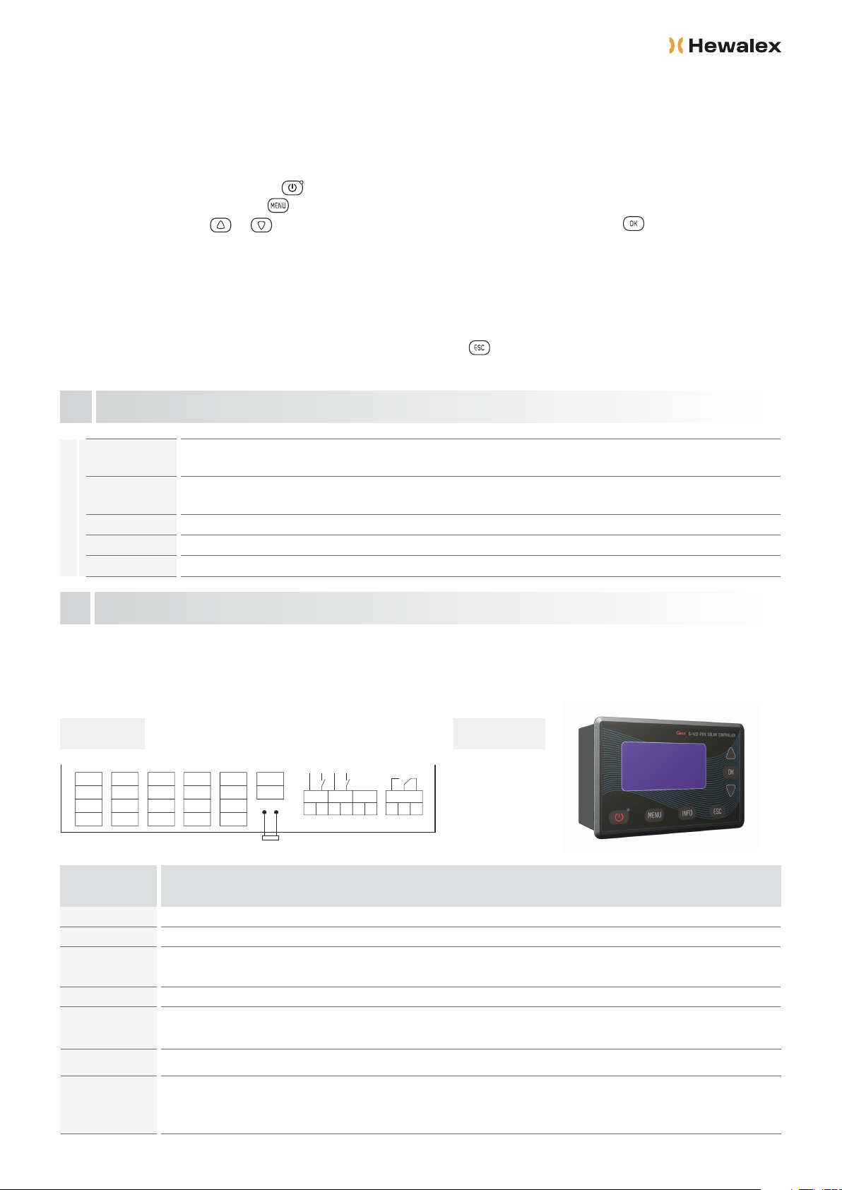
5 G422 ELECTRONIC CONTROLLER
Back view Front view
4 SIGNALLING OF THE FUNCTIONING OF THE PUMP
pump does not work, power failure on the 3-wire cable (check the pump connection – 3-wire cable 230V, check the controller)
no signal
pump does not work, PWM power failure on 2-wire cable, 230V power on 3-wire cable (check the pump connection – 2-wire cable
PWM, check the controller, check the setting PUMP TYPE->PUMP ST7 PWM2 in the controller)
flashing green light
pump works properly
solid green light
pump failure
red light
pump failure
green + red light
Input / Output Description
230V~
O1
O2
O3
O4
Connection to 230V~/50Hz mains
Main pump output – Maximum current intensity: 2A
Relay output - potential-free output (changeover contact) – Maximum current intensity: 4A
– S1-S2 – NC (normally closed), – S2-S3 – NO (normally open)
Relay output – potential output – Maximum current intensity 4A
T1, T2, T3, T4,
5-8
Temperature sensors' input – NTC10kΩ
Output voltage of 230V ~ bridged inside the controller. This output can be bridged on the outside with the output
of a changeover contact O2 to get a switched power supply to control for example a three-way valve
FS-300A control unit and pressure sensor (NO) input
5.................+12V............................red wire
6.................GND............................ black wire / PRESSURE SENSOR
7.................+FRQ...........................white wire
8................. PRESSURE SENSOR
f.
g.
h.
i.
j.
k.
diode
11.01.2023

4
PWM control input to control ST7PWM2 pump
11...............PWM - 12...............PWM +
Communication input RS485 to connect a computer or other device
9.................+A 10...............-B
9 - 10
11 - 12
Fig. 5. Schematic and electric diagram of the installation no. 1
Controller is equipped with an LCD screen and 7 buttons. After correct electric connection, switch on the controller by pressing the button .
In normal operation of the controller the screen displays:
Current program number and diagram of the installation,
Current date and time,
Current temperatures in respective measurement locations (a lack of the sensor is indicated by displaying “- - -“ message, and damage of the sensor
by displaying “Err” message)
During pump operation (symbol of the pump is flashing) alternating message are displayed: temporary power of solar collectors, flow of the heat fluid,
power absorption by the pump of the solar collectors
Pressing the button swill cause entry into the general controller menu.
ź Using directional buttons and select the desired option and confirm by pressing the button .
ź
ź
ź
ź
Description of the G422 controller
ATTENTION!!! Dashed lines refer to optional sensors than can be installed but are not required for correct operation of the
controller (schematic and electric diagram of the installation no. 1).
Description of control parameters for first version of the program
Alarms indicated by the controller
Solar collector type
Difference between temperatures T1,T2 – pump ON
Parameter
Maximum temperature T2 to switch
off the collectors pump
Speed regulation of collectors pump
Protection against overheat of the collectors
Maximum temperature T2 to switch
off the protection against the overheat
Protection against freezing of the collectors
4 – 15 °C
10 – 85 °C
YES / NO
YES / NO
60 – 85 °C
YES / NO
flat / tube
Description Range
Temperature sensor error
The controller checks whether temperature sensors have been connected. If a temperature sensor gets damaged, a cable gets broken, a sensor gets disconnected, the
controller will raise sensor alarm. During an alarm all the outputs are disconnected. Moreover, when the controller displays the main screen, the alarm might be signaled
by sound. In the alarm mode it is possible to browse the menu, configure parameters or manually control external devices. Information on which sensor raises alarm is
available on the main screen. Next to the sensor marking, "Err” will be displayed instead of temperature. If the controller raises sensor alarm it should be checked
whether the system has been assembled correctly, the sensor have been correctly connected and whether the temperature system is not damaged.
Lack of required flow
The controller checks heat carrier flow (option of cooperation with an electronic FS-300A flow meter switched on - the flow / rotameter option)
Measurement: Electr. FS-300A. Lack of flow is controlled in two steps.
ź1st step – (when there is no flow for 20 seconds) the controller generates a sound and displays the following message: LACK OF REQUIRED FLOW. CHECK AND
ADJUST. Once you accept the message with the key, the message will disappear and the sound will no longer be emitted.
ź 2nd step – (when there is no flow for 5 minutes) the controller switches solar collector pump off and displays the following message: NO FLOW, PUMP DAMAGE, AIR-
LOCKED INSTALLATION, BLOCKED FLOW. Once the user accepts this message with the key, the solar collector pump will be switched on again. If there still is no
flow, the alarm will go on in cycles.
Lack of required pressure
The controller is equipped with a pressure control of the heat carrier. The pressure drop is indicated by a sound and the following message: LACK OF REQUIRED
PRESSURE. By removing the cause of the pressure lack and pressing the key the alarm will be switched off.
ATTENTION!!! All options are described in details in the separate manual of the controller.
Input / Output Description
Selection of a type of the solar collector
Difference between temperatures (T1-T2) to switch on the solar collectors pump P.
Maximum permissible temperature of the heater above which the solar
collectors pump will be switched off.
Optional variable speed control of the solar collector pump.
Optional protection against overheat of the solar collectors.
Maximum permissible temperature of the heater above which the solar collectors
pump will be switched off for preheating option.
Optional protection against freezing of the solar collectors.
11.01.2023
Other Hewalex Water Pump manuals

Popular Water Pump manuals by other brands

KSB
KSB Amacan P 700 - 470 Installation & operating manual

Hayward
Hayward 6060 owner's manual

EHEIM
EHEIM compactON 2100 operating instructions

Larius
Larius Pegaso Operating and maintenance instruction

Xylem
Xylem Bell & Gossett VSC Series instruction manual

Neptun
Neptun NBP 18 Original operating instructions

Graco
Graco Merkur Instructions - parts

Grundfos
Grundfos KPC Series Installation and operating instructions

Prio
Prio Prio Jet X845 user guide

pumpa
pumpa BLUE LINE PSP Series Translation of the original instruction manual

Barracuda PUMPS
Barracuda PUMPS 6913867 Installation and operating instructions

GORMAN-RUPP PUMPS
GORMAN-RUPP PUMPS RP4D60 Installation, operation, and maintenance manual with parts list


