Prio Prio Jet X845 User manual
Prio®Jet
User’s Guide
Model X845
External Booster
Pump Box
with Auto Flush for
50-100GPD
Reverse Osmosis
Filtration Systems
Model X855
External Booster
Pump Box
with Auto Flush for
Direct Flow
(Tankless)
Reverse Osmosis
Filtration Systems

2
Before operating this unit, please read the instructions carefully. You may
want to save this guide for your future reference.
Safety Warning
Plug the unit into an electrical outlet only aer you nished the installation.
Check if the voltage indicated on the unit corresponds to the local mains
voltage before you connect the appliance.
Do not use the unit if it is damaged in any way. Take it to an authorized
service center for repair.
Do not open the unit. There are no serviceable parts inside.
When unplugging the unit from the mains, do not pull on the power cord.
Avoid touching the plug with wet hands.
Do not block air vents of the unit or place any items on it. Do not place
the unit near the sources of heat, radiators, etc. Do not place it in a tightly
closed space where it may overheat.
Keep the unit out of reach of pets or other animals.
In case of leakage malfunction or water presence around the unit shut
o the electrical power to the circuit rst, then pull the plug out of the
electrical outlet.
Remove the plug from the electrical outlet during your vacations or other
extended periods of time when the appliance is not in use.
Unplug the unit from the electrical outlet while servicing your water lter
system, and changing the membrane or lters.
Do not use the appliance if operating requirements such as water
temperature/water pressure/electrical supply, etc. are not met. Follow
other applicable regulations such as operating requirements for your
R.O. system. Note that the appliance contains the booster pump that
increases the line water pressure prior to the R.O. unit. Check if that
pressure is acceptable for your device.
Do not use the appliance with water that is microbiologically unsafe or of
unknown quality without adequate disinfection before or aer the system.
This appliance was not designed to be used with power cord extenders,
power lters, external transformers, outlet splitters, etc.
Never store or operate the appliance in direct sunlight.
This appliance is not intended for use by persons (including children) with
reduced physical, sensory or mental capabilities, or lack of experience
and knowledge, unless they have been given supervision or instruction
concerning use of the appliance by a person responsible for their safety.
Children should be supervised to ensure that they do not play with the unit.
At the end of its life, the appliance should be disposed of in an appropriate
manner.
Disposal
Old appliances still contain many recyclable materials. Therefore, please
take used unit to your retailer or recycling center so that it can be recycled.

3
Description
Congratulations on your purchase of the Prio® Jet booster pump box! Please familiarize
yourself with the general concept behind the product and main modes of operation.
Booster pump box models X845 and X855 were designed for 50-500 GPD rated Reverse
Osmosis water ltration systems for use in areas with low water pressure, or for users that
want maximum performance and the best quality ltered water from their R.O. systems.
Both models include the microcontroller and LED indicators for the hassle-free, fully
automatic operation and easy reading. They may be purchased separately to upgrade existing
compatible systems or be included in the high-end R.O. water ltration sets.
Model X845 is designed for 50-100 GPD rated R.O. units usually equipped with the water
collection container such as water pressure tank. Model X855 is designed for 150-500 GPD
rated R.O. machines, both direct ow (“tankless”) or with water tank.
Key Features:
Automatic ush valve: for peak performance and healthier membrane. 18 seconds of
powerful ush at the end of each water ltration cycle prevent the scale and debris build-
up on the membrane outer surface.
Powerful booster pump increases pressure to radically improve the performance
and eectiveness of the R.O. unit in all three key areas: increases ltered water ow
(production rate), increases rejection rate (improves water purication quality), increases
recovery rate (decreases amount of waste water).
Prolongs the membrane and pre-lter(s) service life due to increased recovery rate.
Fully automatic operation, no service necessary: plug and forget.
LED indicators: easily understand what the state of your R.O. unit is. Ever wondered
whether your tank is full or empty? No more guess!
Split, exible installation possible where needed: install the pump box up to 50 feet away
from the R.O. unit itself. Useful for the situations like lack of space or lack of electrical
outlet under the sink, or moving the unit to more appropriate place.
Idling protection: if you forget to close the ltered water faucet for a long time the pump
will shut down automatically for you.
Full separation of electrical components from the membrane and lters of the main R.O.
unit makes the regular servicing of your R.O. machine both easy and safe: no need to
worry about electrical valves and wires while changing your water lters or membrane.
Quick ttings for easy tube connections.

4
How It Works:
Aer the install use your R.O. unit as you normally would.
If your tank is not full the pump box will turn on automatically
and quickly ll it up with ltered water. Then it will ush the
membrane and shut o automatically. If you open the faucet
and take some ltered water from the tank the pump will
turn on automatically to rell the tank again.
For direct ow systems, just open the ltered water
faucet. The pump will turn on automatically and will
produce ltered water in real time until you close the
faucet. At the end of each water production cycle the
membrane will be ushed for 18 seconds, and then the
system will shut o automatically.
LED Indicators:
No Source: there is no water in the inlet line or it’s pressure is less than 7.25 psi (0.05
MPa). Make sure the inlet tube is connected and not kinked, and the water inlet valve is
open.
Working: the pump is working and connected R.O.machine is producing the ltered water
for you. Either tank is not full yet or ltered water faucet is open. No action is required.
Ready: ltered water faucet is closed and tank (if installed) is full. The pump is o. No
action is required.
Flush: 18 s membrane ush is going. No action is required.
Reset: idling protection was triggered. The pump is o. To restore normal operation
power cycle the unit.
Pressure Switches:
The unit is equipped with low and high pressure switches. The low pressure switch shuts o
the pump when there is no inlet water or its pressure is too low. The high pressure switch
shuts o the pump when the ltered water faucet is turned o and tank is full (if installed) and
high back pressure of the ltered water line is built.
Pump:
The unit is equipped with the low voltage booster pump powered by the included transformer
for safe operation.
Precaution:
Please do not use the model X855 with R.O. units equipped with low-production membranes
of ow rating less than 150 GPD. Also, your membrane should be “true” thin lm composite
R.O. membrane, not nano-membrane. The latter is usually identied by word ‘Nano’ or ‘LP’ or
‘ULP’ in the membrane model description. ULP/Nano membranes may be damaged overtime
by powerful pump of X855. Consult your service provider for proper type of R.O. membrane.
Upgrade your membrane if necessary.
Model X845 can be used with both R.O. and ULP/Nano membranes of 50-100 GPD rating.
Neither model is suitable for ultra-ltration (UF) systems.

5
Direct Flow R.O. Systems Benets:
Model X855 makes it possible to build high-end direct ow R.O. machines that oer best in
class performance and water quality.
Freshness of water ltered in real time. No more stale water from a tank.
Virtually unlimited ltered water production. While conventional systems with tanks are limited
by the tank and require prolonged timeouts to rell the tank, a direct ow system is limited by
the membrane ltration rate only. It is also easily scalable by upgrading the membrane.
Instant and sustained ltered water ow. It doesn’t depend on how full the tank is. This is
particularly important for commercial applications too. No more waits for tank rell either.
Space-saving, compact installation since tank is not needed.
Better water purication quality due to improved contaminant rejection rate.
Typically, up to three times less water is wasted per gallon of ltered water due to high
recovery rate as compared to classical tank systems. Saves you money and Planet Earth’s
water resources!
Lower cost of ownership due to prolonged service life of pre-lters and membrane, which
is in turn a result of higher eciency rate: less water is treated overall by pre-lters and
the membrane for each gallon of permeate produced. This saves the capacity of pre-lters
and ensures either less frequent change necessity or better purication.
Less number of components leads to better reliability.
Specication
Operating Requirements:
Minimum inlet water pressure: 7.25 psi (0.05 MPa)
Maximum inlet water pressure: 61 psi (0.42 MPa) / 80 psi (0.55 MPa) when used together
with select Prio® R.O. units
Minimum water temperature: 41 oF (5 oC)
Optimal water temperature: 59–77 oF (15–25 oC)
Maximum water temperature: 95 oF (35 oC) / up to 105 oF (40.5 oC) short-term
Ambient air temperature: 41–105 oF (5–40.5 oC). Indoor use only.
Water source: tap water supply, chlorinated or non-chlorinated, bacteriologically safe
Supply water pH range: 4.0-11.0
Supply water turbidity: < 1 NTU
Supply water components: Hardness (CaCO3) <180 mg/L (<10.5 gpg), Iron <0.1 mg/L,
Manganese <0.05 mg/L, Hydrogen Sulde 0.00 mg/L
Maximum supply water TDS: 1000 ppm
Electrical input: AC 100-240V 50/60 Hz
Maximum length of the line between the unit and the membrane (“split installation”): 50
(15 m) (purchase of extra tubing may be required)
Tubing: ¼”
Weight and Size:
Size (WDH), body only, excluding protrusions: 8.74 x 4.80 x 12.44” (222 x 122 x 316 mm)
Weight, without water and tubing:
8.2 lbs (3.7 kg) for X845;
8.6 lbs (3.9 kg) for X855

6
Performance Guidelines:
Performance of the appliance such as pressure boost or ow rate of the connected R.O. unit is
highly dependent on local conditions (inlet water pressure, temperature and TDS, R.O. membrane
type and ow rating, R.O. unit type and its design specics) and R.O. system use pattern.
Typical pressure boost (
∆
P, extra pressure built upon the inlet pressure) is up to 50 psi
(0.34 MPa) for 50-100 GPD R.O. membrane for X845, and up to 100 psi (0.69 MPa) for
150-500 GPD membrane for X855. For example, the higher the GPD rate of the membrane
attached or the higher the water temperature the lower is an actual pressure boost for
a given setup but the higher the output ow rate in working mode. Typically, in working
mode outlet water pressure reaches 80-110 psi for X845 and 110-160 psi for X855
depending on local conditions and membrane used.
Drain water ow restrictor: 300 cc (ml/min) nominal, up to 450 cc in working mode, open
ow in ush mode.
Auto-ush duration: 18±10% s
Idling protection: 120 minutes (the unit will shut-o the pump and goes into ‘reset required’
mode if working mode continuous duration reaches 2 hours without interruption)
Warranty:
1 year limited warranty
Package Contents:
(1) The auto-ush booster pump box unit
(20 / 6 m) Water tubing ¼”
(1) ¼” x ¼” x ¼” union tee quick tting
(1) ¼” x ¼” union check valve
User’s guide
Installation
Notes:
1. Install your R.O. machine rst. Usually, steps include: inlet valve installation, drain saddle
installation, ltered water faucet installation, tank and tank valve installation, etc. See your
R.O. machine manual for the detailed instructions. Do not open inlet valve until you nish the
unit setup. If you used your R.O. machine before close the inlet valve and drain the water tank
(by opening the ltered water faucet).
2. If your R.O. machine includes ow restrictor, 4-way shut o valve, manual ush valve
remove them on the R.O. unit itself. Built-in components of the pump box will be used instead.
See the following charts for proper connection scheme.
3. Use of air gap faucet is not recommended in R.O. systems with powerful auto ush feature
due to high ow of waste water during the ush. If you have air gap faucet you may simply not
use its waste line and insert waste water tubing directly into the drain saddle (bypassing the
air gap). You may want to use a check valve (optional) on the drain line then to obtain same
protection from a drain water backset as air gap provides.
4. During installation you will need to cut the supplied ¼” tubing into segments as needed.
Use your utility knife for that or similar tool. See the following charts to determine the
7
connection scheme and length of hoses necessary. You may need to purchase extra tubing
for far-reaching split or other corner case installations.
5. It is recommended to connect the unit between the nal pre-lter and the membrane if
your R.O. machine design permits such connection. It protects the pump and helps avoiding
the unneeded pressure on pre-lter(s). Otherwise connect the unit prior to your rst pre-lter
(5 micron PP sediment in-line lter or equivalent is still recommended prior to the unit; point-
of-entry sediment lter works just ne for this purpose).
6. Do not connect the unit to the electrical supply until the Setup is completed.
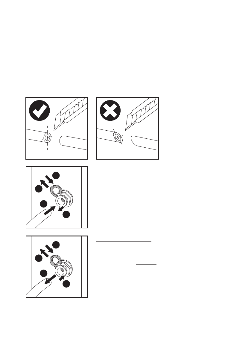
IMPORTANT: Cut tubing at 90 degrees to ensure a watertight seal:
To Connect the Tubing to a Fitting:
1. Remove the lock if present (not present in self-locking
ttings).
2. Push. Insert the tube rmly until full stop.
3. Pull the collet back slightly.
4. Replace the lock (if present).
To Disconnect the Tubing:
1. Remove the lock if present (not present in self-locking
ttings).
2. Push the collet and hold.
3. Pull the tubing out.
4. Replace the lock (if present).
1
4
3
2
1
4
2
3
No skewed cut!

8
Unit Placement Guide:
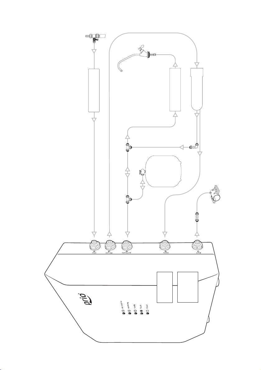
Hose Connections:
Important: if your R.O. machine includes 4-way shut o valve (control valve), ow restrictor,
manual ush valve remove them on the R.O. system itself. The unit’s internal components
will be used to provide the same or enhanced functionality. The unit is not compatible with
R.O. systems with built-in (non-removable/non-bypassable) control valve or ow restrictor.
1. Insert water supply tubing from nal pre-lter into the “inlet” tting of the unit.
2. Insert the supply tubing from the “RO unit” tting of the unit into the supply inlet of the
membrane housing.
3. Insert the ltered water tubing from the ltered water outlet of the membrane housing
into the “permeate” tting of the unit. Use included extra union tee tting if needed.
4. Insert the waste tubing from the waste water outlet of the membrane into the “waste”
tting of the unit.
5. Insert the waste tubing from the “drain” tting of the unit into the drain saddle (optionally
through the union check valve or through the air gap faucet on the way) or to a waste
water collection container.
See the following charts for details.
9
inlet
valve
filtered
water
faucet
membrane supply inlet
from final pre-filter
post-filter
check
valve
tank
drain saddle
permeate
(center outlet)
waste (side outlet)
union tee
fitting
pre-filter(s)
X845
X855
with tank
tank
valve
union tee
fitting
General R.O. System with Tank Connections
from final pre-filter outlet
to supply inlet of the membrane
from filtered water outlet of the membrane
from waste water outlet
of the membrane
to drain or
waste water
collection container
check valve
(optional)
membrane

10
inlet
valve
filtered
water
faucet
from final pre-filter
pre-filter(s)
membrane supply inlet
high-production
membrane
post-filter
check
valve
drain saddle
union tee
fitting
X855
direct flow
General Direct Flow R.O. System Connections
from final pre-filter outlet
to supply inlet of the membrane
from filtered water outlet of the membrane
from waste water outlet
of the membrane
to drain or
waste water
collection container permeate
(center outlet)
waste (side outlet)
check valve
(optional)
11
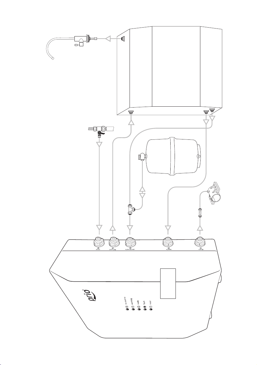
X845
Prio® Expert MO600 R.O. System Connections
drain saddle
R.O. unit
inlet
MO600
tank
inlet valve
waste water outlet
permeate outlet to the tank
union tee fitting
from waste water outlet
of the membrane
to drain or
waste water
collection container
check valve
filtered
water
faucet
from inlet valve
to R.O. unit inlet
from filtered water outlet of the R.O. unit

12
X855
Prio® Expert MOD600 Direct Flow R.O. System Connections
waste water outlet
permeate outlet
R.O. unit
inlet
inlet
valve
drain saddle
MOD600
filtered
water
faucet
from inlet valve
to R.O. unit inlet
from filtered water outlet of the R.O. unit
from waste water outlet of the R.O. unit
to drain or
waste water
collection container
check valve
(optional)

13
OD360
pre-filter
post-filter
pre-filter
inlet
post-filter
inlet
filtered
water
faucet
inlet
valve
drain saddle
check
valve
membrane
union tee fitting
pre-filter
outlet
waste water
outlet of the
membrane (side)
permeate
outlet of the
membrane
(center)
membrane
inlet
X855
Prio® Expert OD360 Direct Flow R.O. System Connections
from final pre-filter outlet
to supply inlet of the membrane
from filtered water
outlet of the membrane
from waste water outlet
of the membrane
to drain or
waste water
collection container
check valve

14
Initial Washing:
Aer installation it is recommended to perform the initial washing of the unit and connected
R.O. system.
For this, for R.O. systems with tank:
close the tank valve;
open the inlet valve;
open the ltered water faucet;
plug the unit’s power cord into the electrical outlet;
wait for water to arrive at the faucet (it may take a while, water ow usually is not high,
water foam and air may be going out of the system);
wait 1-2 minutes for more or less steady (yet usually low) water ow from the faucet and
close the faucet;
wait for auto ush to complete (18 s);
repeat steps “open faucet – wait 1-2 minutes – close the faucet – wait for auto ush to
complete” at least 5 times;
aer you nished with previous step close the faucet and open the tank valve;
wait for the tank to ll to full (until “ready” LED indicator lights up) then drain the tank
completely by opening the faucet;
you may repeat the tank full rell – tank drain once again;
aer you close your faucet the tank will rell again, and your system is ready for use.
For direct ow R.O. system:
open the inlet valve;
open the ltered water faucet;
plug the unit’s power cord into the electrical outlet;
wait for water to arrive at the faucet (it may take a while, water foam and air may be going
out of the system);
wait 2 minutes for more or less steady water ow from the faucet and close the faucet;
wait for auto ush to complete (18 s);
repeat steps “open faucet – wait 2 minutes – close the faucet – wait for auto ush to
complete” 5-10 times;
aer you nished with previous step close the faucet, and your system is ready for use.
Please note that aer initial installation of the unit and/or R.O. machine or changing the
lters or membrane, air contained in the new dry system or lter may come out sometimes
producing foamy, white ltered water. Water may look white due to tiny air bubbles in it. If you
leave the water to stand for few minutes all bubbles will surface and eliminate. Such aerated
water is clean and safe. Gradually over the coming days all air inside your system will nd
its way out. To make this process faster you may repeat the initial washing procedure until
you’re pleased with the result. Also note that if for some reason the water supply contains a
lot of dispersed air, your R.O. machine may start producing aerated water again. The unit’s
internal pipes and components never take air from outside as they are completely air and
water sealed and leak-free.

15
Regular Use
Aer the installation use your R.O. unit as you normally would.
If your tank is not full the unit will turn on automatically and ll it up with ltered water. Then
it will ush the membrane and shut o automatically. If you open the faucet and take some
ltered water from the tank the pump will turn on automatically to rell the tank again.
For direct ow systems, just open the ltered water faucet. The pump will turn on
automatically and will produce the ltered water ow in real time until you close the faucet.
At the end of each water production cycle the membrane will be ushed, and then the system
will shut o automatically.
Please note that R.O. membranes (especially dry ones) need up to 50 hours of active operation
before they reach peak performance in terms of water ow, recovery and rejection rates.
For your safety and peace of mind please unplug the unit from the electrical outlet and close
the inlet valve before servicing your R.O. system such as changing the lters or membrane,
or during vacations.

Prio, Prio logo are the trademarks of DWT Deutsche Wassertechnologien GmbH, Germany.
As used herein, ® denotes registered trademark status in Germany only.
Copyright © DWT Deutsche Wassertechnologien GmbH, Germany, 2014, 2018
This manual suits for next models
1
Table of contents
Popular Water Pump manuals by other brands


GORMAN-RUPP PUMPS
GORMAN-RUPP PUMPS 112D60-B Installation, operation, and maintenance manual with parts list

WOERNER
WOERNER GMF Translation of the original operation manual

Flotec
Flotec SCM 4 PLUS Series Use and maintenance manual

Pentair
Pentair CRISTAL-FLO II Installation and user guide

LEYBOLD
LEYBOLD EcoDry - M Series operating instructions

Gardena
Gardena 8200 Operator's manual


