Hewlett Packard Enterprise ProLiant DL360 Gen10 Plus User manual

HPE ProLiant DL360 Gen10 Plus Server User GuideHPE ProLiant DL360 Gen10 Plus Server User Guide
Part Number: 30-3C49FD5E-001
Published: May 2021
Edition: 1

HPEHPE ProLiant DL360 Gen10 Plus Server User Guide ProLiant DL360 Gen10 Plus Server User Guide
AbstractAbstract
This document is for the person who installs, administers, and troubleshoots servers and storage systems. Hewlett Packard Enterprise
assumes you are qualified in the servicing of computer equipment and trained in recognizing hazards in products with hazardous energy
levels.
Part Number: 30-3C49FD5E-001
Published: May 2021
Edition: 1
© Copyright 2021 Hewlett Packard Enterprise Development LP
NoticesNotices
The information contained herein is subject to change without notice. The only warranties for Hewlett Packard Enterprise products and
services are set forth in the express warranty statements accompanying such products and services. Nothing herein should be construed as
constituting an additional warranty. Hewlett Packard Enterprise shall not be liable for technical or editorial errors or omissions contained
herein.
Confidential computer software. Valid license from Hewlett Packard Enterprise required for possession, use, or copying. Consistent with FAR
12.211 and 12.212, Commercial Computer Software, Computer Software Documentation, and Technical Data for Commercial Items are
licensed to the U.S. Government under vendor's standard commercial license.
Links to third-party websites take you outside the Hewlett Packard Enterprise website. Hewlett Packard Enterprise has no control over and is
not responsible for information outside the Hewlett Packard Enterprise website.
AcknowledgmentsAcknowledgments
Intel , Itanium , Optane , Pentium , Xeon , Intel Inside , and the Intel Inside logo are trademarks of Intel Corporation in the U.S. and
other countries.
Microsoft , Windows , and Windows Server are either registered trademarks or trademarks of Microsoft Corporation in the United States
and/or other countries.
Linux is the registered trademark of Linus Torvalds in the U.S. and other countries.
VMware ESXi and VMware vSphere are registered trademarks or trademarks of VMware, Inc. in the United States and/or other
jurisdictions.
Red Hat Enterprise Linux are registered trademarks of Red Hat, Inc. in the United States and other countries.
microSD is a trademark or a registered trademark of SD-3D in the United States, other countries of both.
All third-party marks are property of their respective owners.
® ® ™ ® ® ®
® ® ®
®
™ ®
® ®
®

Table of contentsTable of contents
1 Component identification
1.1 Front panel components
1.2 Front panel LEDs and buttons
1.2.1 UID button functionality
1.2.2 Front panel LED power fault codes
1.2.3 Systems Insight Display LEDs
1.2.4 Systems Insight Display combined LED descriptions
1.3 Rear panel components
1.4 Rear panel LEDs
1.5 System board components
1.5.1 Heatsink and socket components
1.5.2 System maintenance switch descriptions
1.5.3 DIMM slot locations
1.5.4 DIMM label identification
1.5.5 Intel Optane persistent memory 200 series for HPE label identification
1.6 Drive numbering
1.7 HPE Basic Drive LED definitions
1.8 Hot-plug fans
1.9 DSC-25 2-port SFP28 card ports and LEDs
1.10 HPE NS204i-p NVMe OS Boot Device components
1.11 HPE NS204i-p NVMe OS Boot Device LED definitions
2 Operations
2.1 Power up the server
2.2 Power down the server
2.3 Extend the server from the rack
2.4 Remove the server from the rack
2.5 Remove the access panel
2.6 Install the access panel
2.7 Remove the hot-plug fan
2.8 Remove the primary PCI riser cage
2.9 Install the primary PCI riser cage
2.10 Remove the secondary PCI riser cage
2.11 Install the secondary PCI riser cage
2.12 Remove the 8SFF drive backplane
2.13 Removing the hard drive blank
2.14 Removing a hot-plug SAS/SATA/NVMe drive
2.15 Release the cable management arm
2.16 Accessing the Systems Insight Display
3 Setup
3.1 Optional services
3.2 Optimum environment
3.2.1 Space and airflow requirements

3.2.2 Temperature requirements
3.2.3 Power requirements
3.2.4 Electrical grounding requirements
3.2.5 Connecting a DC power cable to a DC power source
3.3 Server warnings and cautions
3.4 Rack warnings
3.5 Identifying the contents of the server shipping carton
3.6 Installing hardware options
3.7 Installing the server into the rack
3.8 Operating system
3.8.1 Installing the operating system with Intelligent Provisioning
3.9 Selecting boot options in UEFI Boot Mode
3.10 Selecting boot options
3.11 Registering the server
4 Hardware options installation
4.1 Hewlett Packard Enterprise product QuickSpecs
4.2 Introduction
4.3 Installing a redundant hot-plug power supply
4.4 Energy pack options
4.4.1 HPE Smart Storage Battery
4.4.2 HPE Smart Storage Hybrid Capacitor
4.4.3 Minimum firmware versions
4.4.4 Installing an energy pack
4.5 Memory options
4.5.1 Memory population information
4.5.2 DIMM-processor compatibility
4.5.3 HPE SmartMemory speed information
4.5.4 Installing a DIMM blank
4.5.5 Installing a DIMM
4.5.6 Intel Optane persistent memory 200 series for HPE
4.5.6.1 Persistent memory module-processor compatibility
4.5.6.2 Persistent memory module population information
4.5.6.3 System requirements for persistent memory module support
4.5.6.4 Installing persistent memory modules
4.5.6.5 Configuring the server for Intel Optane persistent memory 200 series for HPE
4.6 Installing a high-performance fan
4.7 Installing an 8SFF display port/USB/optical blank option
4.8 Installing the 4LFF display port/USB option
4.9 Drive options
4.9.1 Installing a hot-plug SAS, SATA or NVMe drive
4.9.2 Installing the 4LFF optical drive option
4.9.3 Installing an 8SFF optical drive
4.9.4 Installing a 2SFF SAS/SATA/NVMe drive cage
4.10 Primary PCI riser cage options

4.10.1 Installing an expansion board in slot 1
4.10.2 Installing an expansion board in slot 2
4.10.3 Installing an optional primary PCI riser board
4.10.4 Installing the NVMe M.2 riser option
4.10.5 Installing an accelerator or GPU in the primary riser cage
4.11 Secondary PCI riser options
4.11.1 Installing a secondary full-height PCI riser cage option
4.11.2 Installing a secondary low-profile PCIe slot riser cage option
4.11.3 Installing an expansion board in the secondary riser cage
4.11.4 Installing an accelerator or GPU in the secondary riser cage
4.12 Storage controller options
4.12.1 Installing a type-a Smart Array storage controller option
4.12.2 Installing a type-p storage controller option
4.13 Processor and heatsink options
4.13.1 Installing a processor heatsink assembly
4.13.2 Installing a high performance heatsink
4.14 Installing the Systems Insight Display power module
4.15 Installing an OCP 3.0 adapter card
4.16 Installing the serial cable option
4.17 Installing the Chassis Intrusion Detection switch option
4.18 Installing the Pensando DSP DSC-25 SFP28 card
4.19 Installing the HPE NS204i-p Gen10 Plus Boot Device option
4.20 HPE Trusted Platform Module 2.0 Gen10 option
4.20.1 Overview
4.20.2 HPE Trusted Platform Module 2.0 guidelines
4.20.3 Installing and enabling the HPE TPM 2.0 Gen10 option
4.20.3.1 Installing the Trusted Platform Module board
4.20.3.1.1 Preparing the server for installation
4.20.3.1.2 Installing the TPM board and cover
4.20.3.1.3 Preparing the server for operation
4.20.3.2 Enabling the Trusted Platform Module
4.20.3.2.1 Enabling the Trusted Platform Module as TPM 2.0
4.20.3.2.2 Enabling the Trusted Platform Module as TPM 1.2
4.20.3.3 Retaining the BitLocker recovery key/password
5 Cabling
5.1 Cabling guidelines
5.2 Front I/O cabling
5.3 Storage cabling
5.3.1 SFF cables
5.3.1.1 8SFF x1 Tri-Mode U.3 backplane + 2SFF NVMe backplane to type-p Tri-Mode controller
5.3.1.2 8SFF x4 + 2SFF backplanes to type-p controller
5.3.1.3 8SFF x4 + 2SFF backplanes to type-a and type-p controllers
5.3.1.4 2SFF x4 backplane to primary NVMe riser
5.3.1.5 8SFF x1 Tri-Mode U.3 backplane to type-p controller on slot 2

5.3.1.6 8SFF SAS/SATA backplane to system board and 2-port type-a controller
5.3.1.7 8SFF x4 backplane to 2-port type-p controller
5.3.1.8 8SFF x4 backplane direct attach
5.3.1.9 8SFF SAS/SATA backplane to embedded SATA
5.3.2 LFF cables
5.3.2.1 4LFF backplane to controllers
6 Software and configuration utilities
6.1 Server mode
6.2 Product QuickSpecs
6.3 Active Health System Viewer
6.3.1 Active Health System
6.3.1.1 Active Health System data collection
6.3.1.2 Active Health System Log
6.4 HPE iLO 5
6.4.1 iLO Federation
6.4.2 iLO Service Port
6.4.3 iLO RESTful API
6.4.4 RESTful Interface Tool
6.4.5 iLO Amplifier Pack
6.5 Integrated Management Log
6.6 Intelligent Provisioning
6.7 Management security
6.8 Scripting Toolkit for Windows and Linux
6.9 HPE Message Passing Interface
6.10 HPE Performance Cluster Manager
6.11 UEFI System Utilities
6.11.1 Selecting the boot mode
6.11.2 Secure Boot
6.11.3 Launching the Embedded UEFI Shell
6.12 HPE Smart Storage Administrator
6.12.1 Smart Storage Administrator
6.13 HPE InfoSight for servers
6.14 USB support
6.14.1 External USB functionality
6.15 Redundant ROM support
6.15.1 Safety and security benefits
6.16 Keeping the system current
6.16.1 Updating firmware or system ROM
6.16.1.1 Service Pack for ProLiant
6.16.1.1.1 Smart Update Manager
6.16.1.1.2 Integrated Smart Update Tools
6.16.1.2 Updating firmware from the System Utilities
6.16.1.3 Updating the firmware from the UEFI Embedded Shell
6.16.1.4 Online Flash components

6.16.2 Drivers
6.16.3 Software and firmware
6.16.4 Operating system version support
6.16.5 HPE Pointnext Portfolio
6.16.6 Proactive notifications
7 Troubleshooting
7.1 NMI functionality
7.2 Troubleshooting resources
8 Removing and replacing the system battery
9 Specifications
9.1 Environmental specifications
9.2 Server specifications
9.3 Power supply specifications
9.3.1 HPE 500 W Flex Slot Platinum Hot-plug Low Halogen Power Supply
9.3.2 HPE 800 W Flex Slot Platinum Hot-plug Low Halogen Power Supply
9.3.3 HPE 800 W Flex Slot Titanium Hot-plug Low Halogen Power Supply
9.3.4 HPE 800 W Flex Slot Universal Hot-plug Low Halogen Power Supply
9.3.5 HPE 800 W Flex Slot -48 VDC Hot-plug Low Halogen Power Supply
9.3.6 HPE 1600 W Flex Slot Platinum Hot-plug Low Halogen Power Supply
9.4 Hot-plug power supply calculations
10 Websites
11 Support and other resources
11.1 Accessing Hewlett Packard Enterprise Support
11.2 Accessing updates
11.3 Remote support
11.4 Warranty information
11.5 Regulatory information
11.6 Documentation feedback

Component identificationComponent identification
Component identification 8
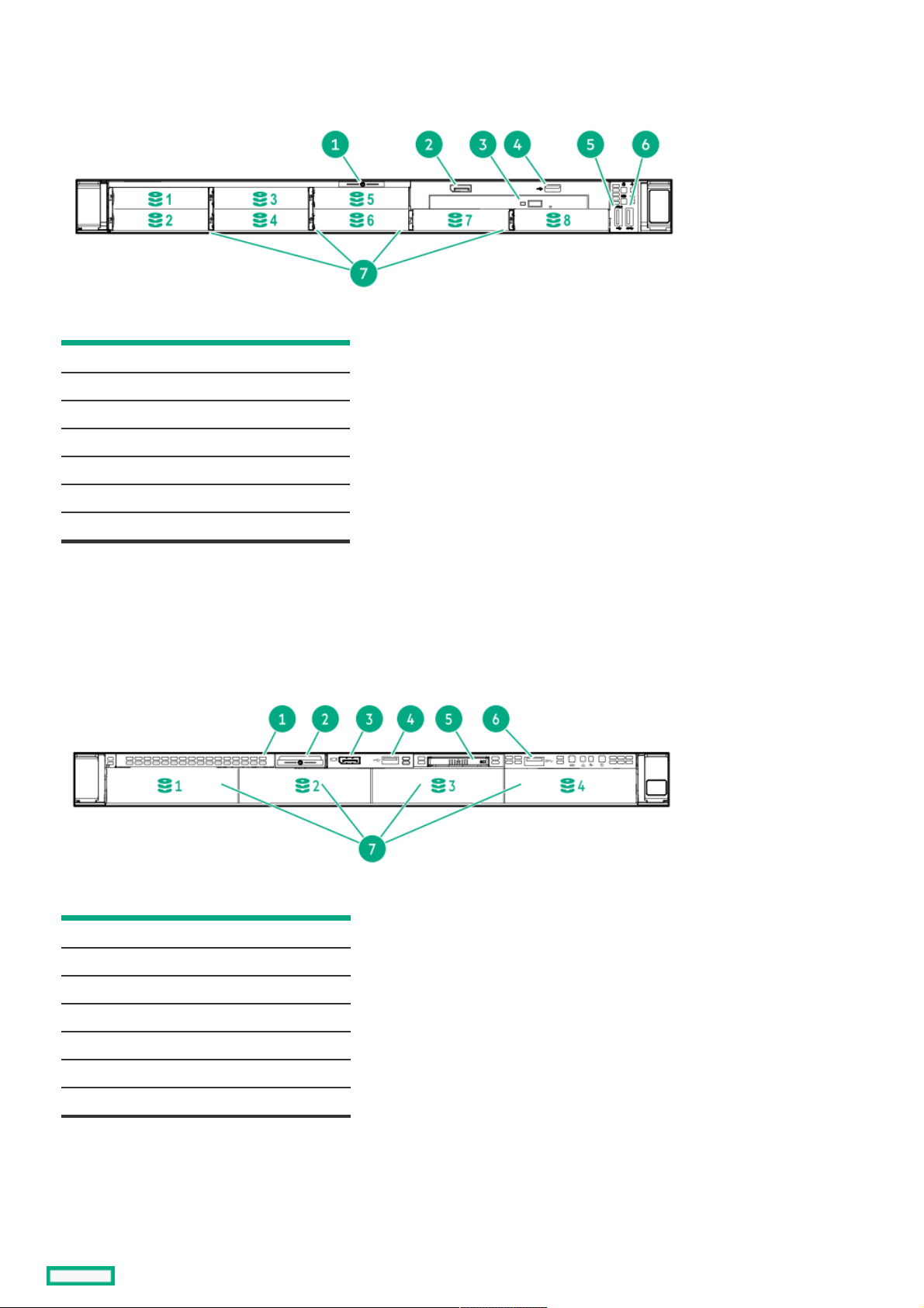
Front panel componentsFront panel components
8SFF8SFF
ItemItem DescriptionDescription
1 Serial number/iLO information pull tab
2 Display port (optional)
3 Optical drive (optional)
4 USB 2.0 port (optional)
5 iLO Service Port
6 USB 3.0 port
7 Drive bays
Optional 2SFF drive bays
The operating system does not recognize this port as a USB port.
4LFF4LFF
ItemItem DescriptionDescription
1 Optical drive blank (optional)
2 Serial number/iLO information pull tab
3 Display port (optional)
4 USB 2.0 port (optional)
5 Systems Insight Display (optional)
6 USB 3.0 port
7 Drive bays
1
1
1
2
1
2
Front panel components 9
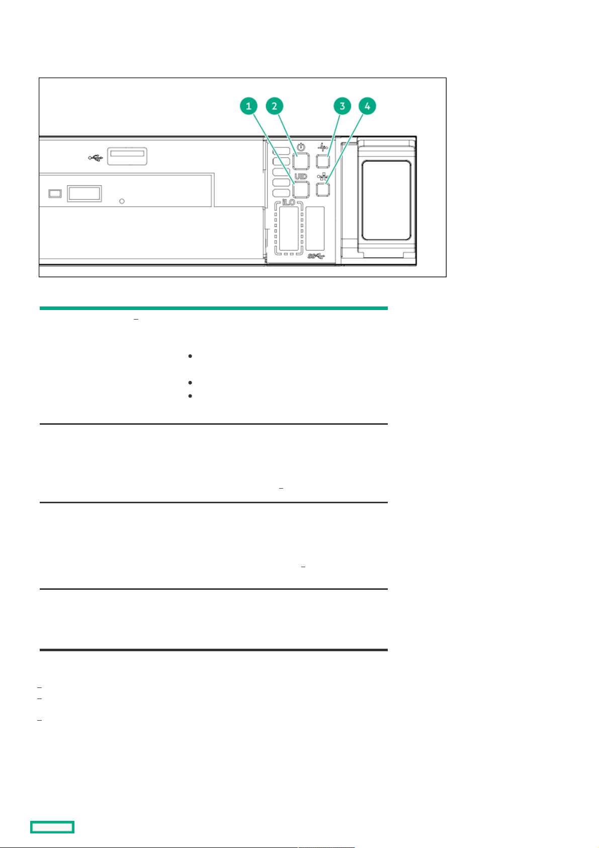
Front panel LEDs and buttonsFront panel LEDs and buttons
8 SFF8 SFF
ItemItem DescriptionDescription StatusStatus
1 UID button/LED Solid blue = Activated
Flashing blue:
1 Hz = Remote management or firmware
upgrade in progress
4 Hz = iLO manual reboot sequence initiated
8 Hz = iLO manual reboot sequence in progress
Off = Deactivated
2 Power On/Standby button
and system power LED
Solid green = System on
Flashing green = Performing power on sequence
Solid amber = System in standby
Off = No power present
3 Health LED Solid green = Normal
Flashing green = iLO is rebooting.
Flashing amber = System degraded
Flashing red = System critical
4 NIC status LED Solid green = Link to network
Flashing green = Network active
Off = No network activity
When all four LEDs described in this table flash simultaneously, a power fault has occurred.
Facility power is not present, power cord is not attached, no power supplies are installed, power supply failure has occurred, or the
power button cable is disconnected.
If the health LED indicates a degraded or critical state, review the system IML or use iLO to review the system health status.
4LFF4LFF
1
1
2
1
3
1
1
2
3
Front panel LEDs and buttons 10
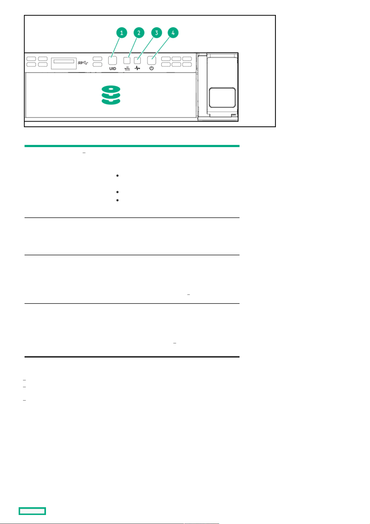
ItemItem DescriptionDescription StatusStatus
1 UID button/LED Solid blue = Activated.
Flashing blue:
1 Hz = Remote management or firmware
upgrade in progress.
4 Hz = iLO manual reboot sequence initiated.
8 Hz = iLO manual reboot sequence in progress.
Off = Deactivated.
2 NIC status LED Solid green = Link to network.
Flashing green = Network active.
Off = No network activity.
3 Health LED Solid green = Normal.
Flashing green = iLO is rebooting.
Flashing amber = System degraded.
Flashing red = System critical.
4 Power On/Standby button
and system power LED
Solid green = System on.
Flashing green = Performing power on sequence.
Solid amber = System in standby.
Off = No power present.
When all four LEDs described in this table flash simultaneously, a power fault has occurred.
To identify components in a degraded or critical state, see the Systems Insight Display LEDs, check iLO/BIOS logs, and reference the
server troubleshooting guide.
Facility power is not present, power cord is not attached, no power supplies are installed, power supply failure has occurred, or the
power button cable is disconnected.
1
1
1
2
1
3
1
2
3
Front panel LEDs and buttons 11

UID button functionalityUID button functionality
The UID button can be used to display the Server Health Summary when the server will not power on. For more information, see the
latest HPE iLO 5 User Guide on the Hewlett Packard Enterprise websiteHewlett Packard Enterprise website .
UID button functionality 12
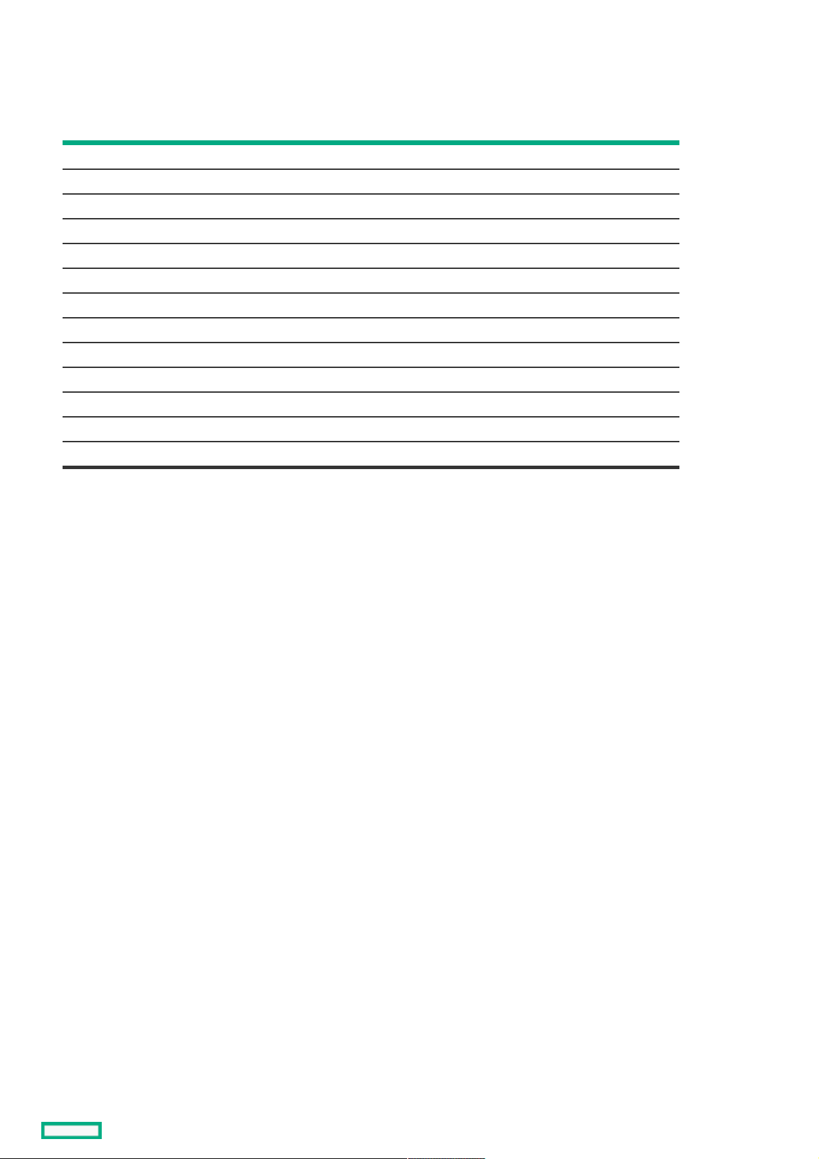
Front panel LED power fault codesFront panel LED power fault codes
The following table provides a list of power fault codes, and the subsystems that are affected. Not all power faults are used by all
servers.
SubsystemSubsystem LED behaviorLED behavior
System board 1 flash
Processor 2 flashes
Memory 3 flashes
Riser board PCIe slots 4 flashes
OCP adapter 5 flashes
Storage controller 6 flashes
System board PCIe slots 7 flashes
Power backplane 8 flashes
Storage backplane 9 flashes
Power supply 10 flashes
PCIe expansion cards installed in riser board 11 flashes
Chassis 12 flashes
GPU card 13 flashes
Front panel LED power fault codes 13
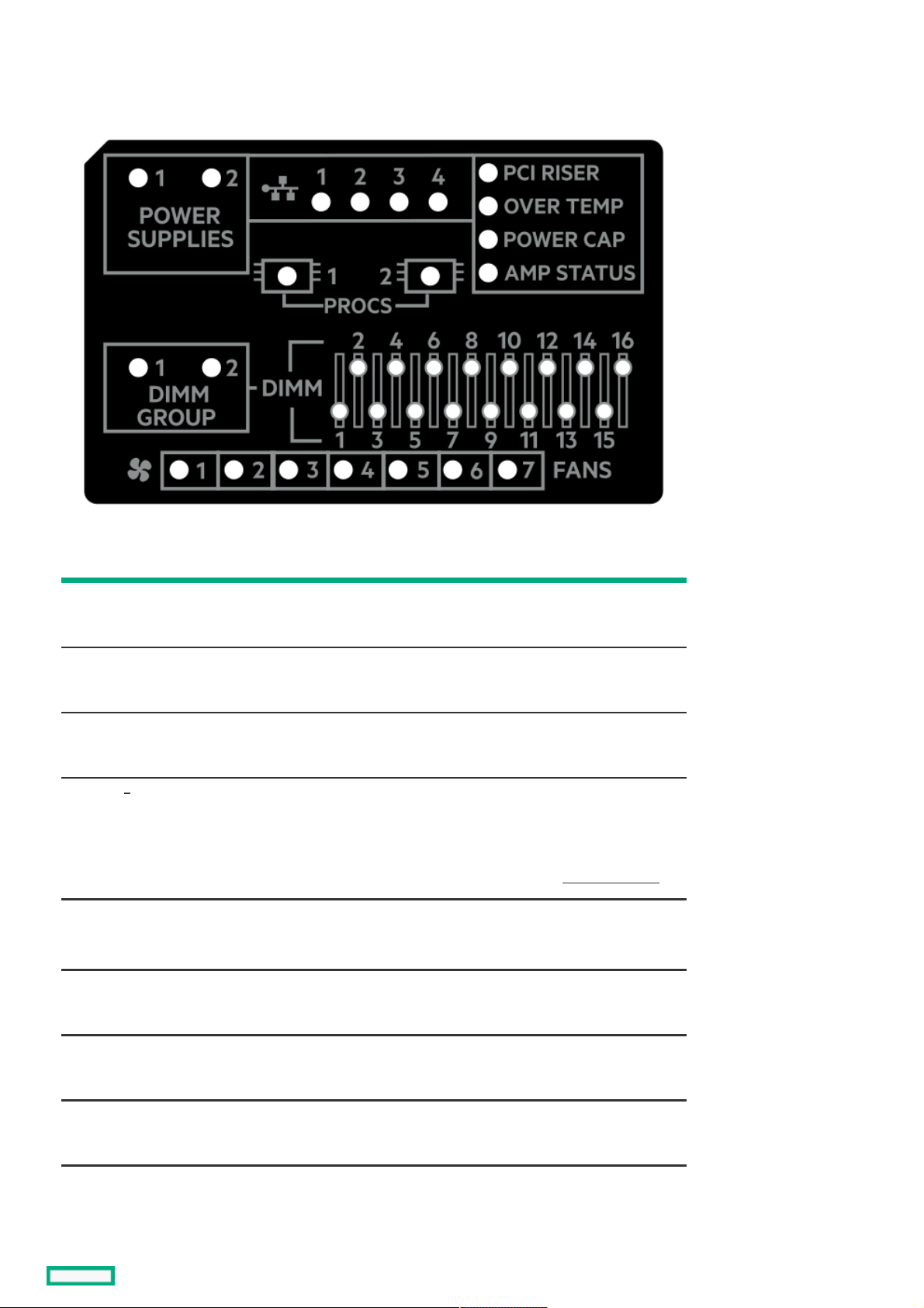
Systems Insight Display LEDsSystems Insight Display LEDs
The Systems Insight Display LEDs represent the system board layout. The display enables diagnosis with the access panel installed.
DescriptionDescription StatusStatus
Processor LEDs Off = Normal
Amber = Failed processor
DIMM LEDs Off = Normal
Amber = Failed DIMM or configuration issue
Fan LEDs Off = Normal
Amber = Failed fan or missing fan
NIC LEDs Off = No link to network
Solid green = Network link
Flashing green = Network link with activity
If power is off, the front panel LED is not active. For status, see Rear panel LEDs.
Power supply LEDs Off = Normal
Solid amber = Power subsystem degraded, power supply failure, or input power lost.
PCI riser LED Off = Normal
Amber = Incorrectly installed PCI riser cage
Over temp LED Off = Normal
Amber = High system temperature detected
Power cap LED Off = System is in standby, or no cap is set.
Solid green = Power cap applied
1
Systems Insight Display LEDs 14

Amp Status LED Off = AMP modes disabled
Solid green = AMP mode enabled
Solid amber = Failover
Flashing amber = Invalid configuration
DescriptionDescription StatusStatus
Embedded NIC ports are not equipped on the server. NIC LEDs on the Systems Insight Display will flash based on the network
adapter port activity. In the case of a dual-port adapters, only NIC LED 1 and 2 will illuminate to correspond with the activity of the
respective network ports.
When the health LED on the front panel illuminates either amber or red, the server is experiencing a health event. For more information
on the combination of these LEDs, see Systems Insight Display combined LED descriptions ).
1
Systems Insight Display LEDs 15
Systems Insight Display combined LED descriptionsSystems Insight Display combined LED descriptions
The combined illumination of the following LEDs indicates a system condition:
Systems Insight Display LEDs
System power LED
Health LED
Systems Insight DisplaySystems Insight Display
LED and colorLED and color
HealthHealth
LEDLED
SystemSystem
power LEDpower LED
StatusStatus
Processor (amber) Red Amber One or more of the following
conditions might exist:
Processor in socket X has failed.
Processor X is not installed in
the socket.
Processor X is unsupported.
ROM detects a failed processor
during POST.
Processor (amber) Amber Green Processor in socket X is in a pre-
failure condition.
DIMM (amber) Red Green One or more DIMMs have failed.
DIMM (amber) Amber Green DIMM in slot X is in a pre-failure
condition.
Over temp (amber) Amber Green The Health Driver has detected a
cautionary temperature level.
Over temp (amber) Red Amber The server has detected a hardware
critical temperature level.
PCI riser (amber) Red Green The PCI riser cage is not seated
properly.
Fan (amber) Amber Green One fan has failed or has been
removed.
Fan (amber) Red Green Two or more fans have failed or
been removed.
Power supply (amber) Red Amber One or more of the following
conditions might exist:
Only one power supply is
installed and that power supply
is in standby.
Power supply fault.
System board fault.
Power supply (amber) Amber Green One or more of the following
conditions might exist:
Redundant power supply is
installed and only one power
supply is functional.
AC power cord is not plugged
into redundant power supply.
Redundant power supply fault.
Power supply mismatch at
POST or power supply
mismatch through hot-plug
addition.
Power cap (off) — Amber Standby.
Systems Insight Display combined LED descriptions 16

Power cap (green) — Flashing
green
Waiting for power.
Power cap (green) — Green Power is available.
Power cap (flashing
amber)
— Amber Power is not available.
Systems Insight DisplaySystems Insight Display
LED and colorLED and color
HealthHealth
LEDLED
SystemSystem
power LEDpower LED
StatusStatus
IMPORTANT: IMPORTANT: If more than one DIMM slot LED is illuminated, further troubleshooting is required. Test each bank of
DIMMs by removing all other DIMMs. Isolate the failed DIMM by replacing each DIMM in a bank with a known working
DIMM.
Systems Insight Display combined LED descriptions 17
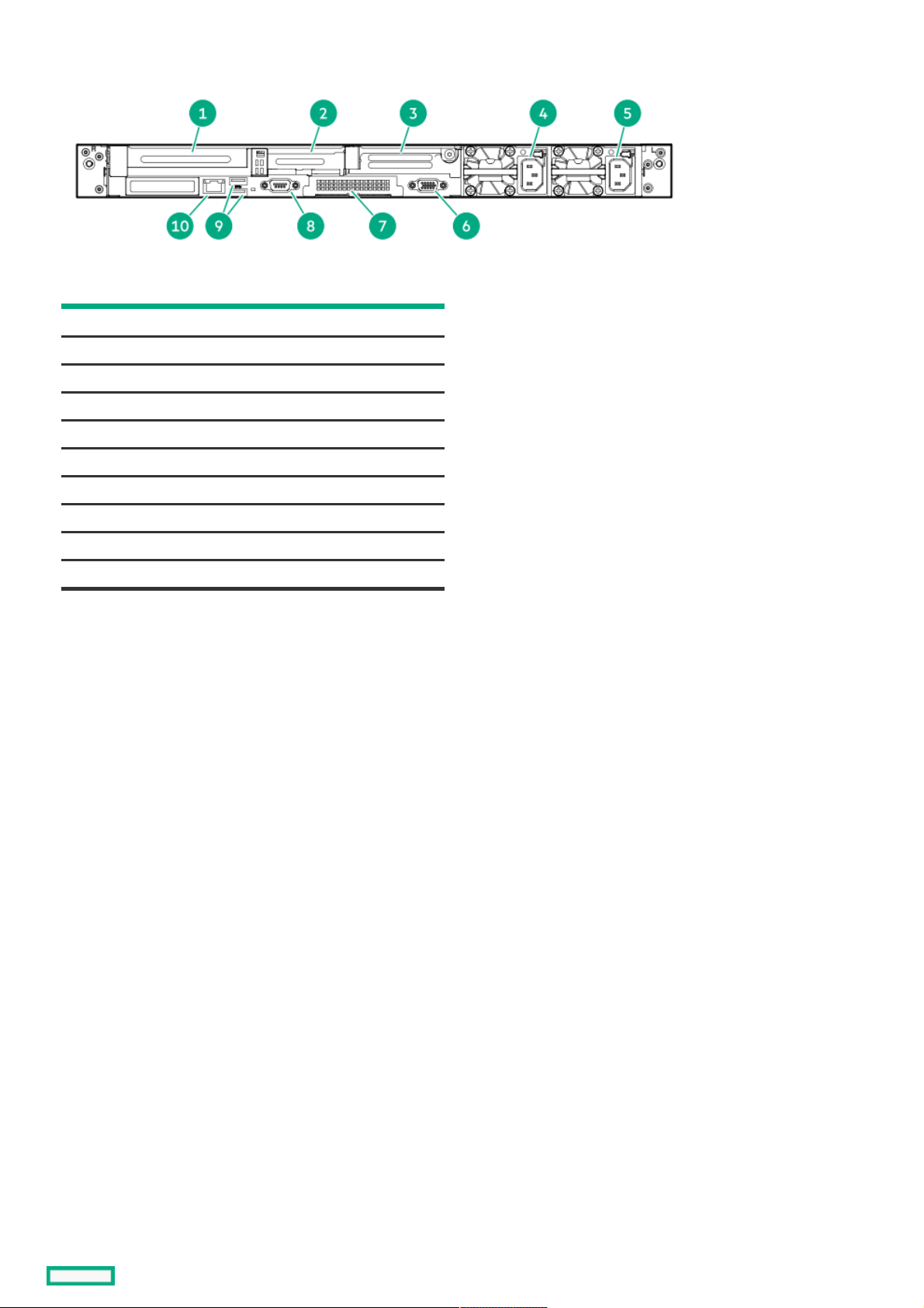
Rear panel componentsRear panel components
ItemItem DescriptionDescription
1 Slot 1 PCIe4
2 Slot 2 PCIe4
3 Slot 3 PCIe4 (optional - requires second processor)
4 Power supply 2 (PS2)
5 Power supply 1 (PS1)
6 Video (VGA) port
7 OCP 3.0 adapter (if equipped)
8 Serial port (optional)
9 USB 3.0 ports
10 iLO Management Port
Rear panel components 18
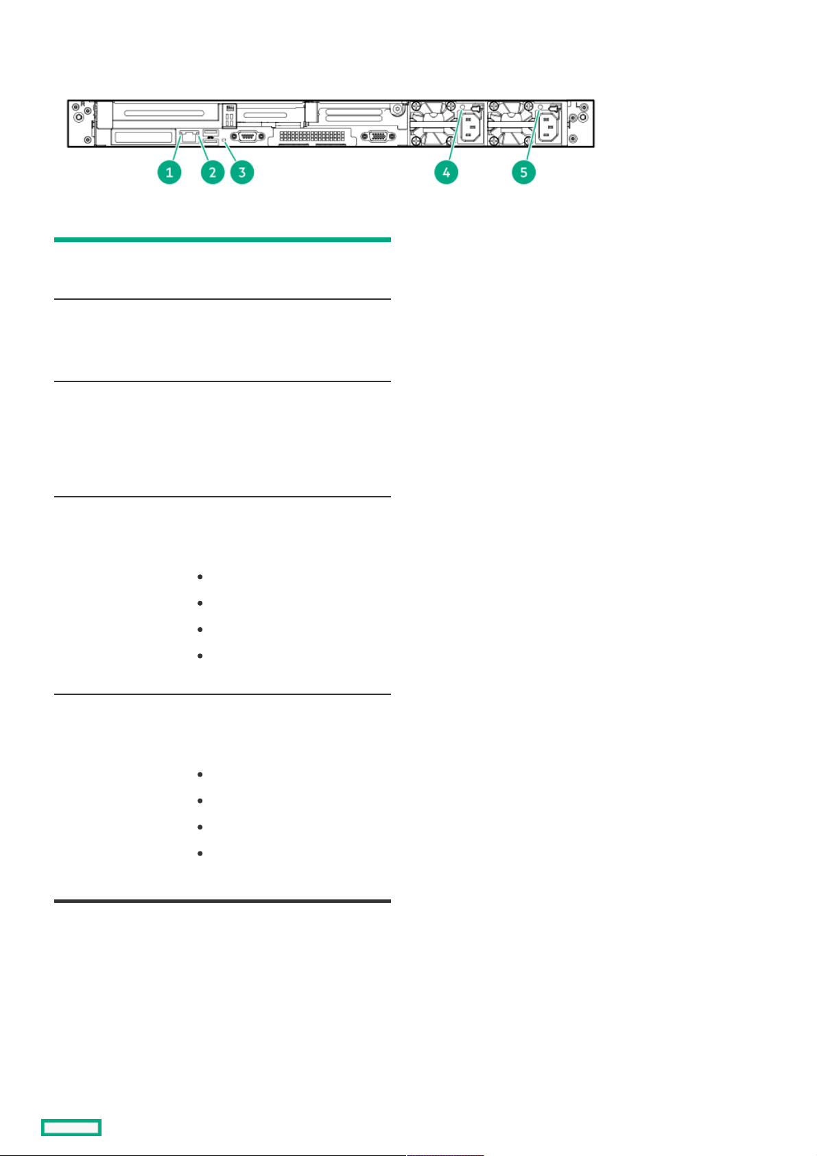
Rear panel LEDsRear panel LEDs
ItemItem DescriptionDescription StatusStatus
1 iLO 5/standard
NIC link LED
Solid green = Link exists.
Off = No link exists.
2 iLO 5/standard
NIC activity LED
Solid green = Activity exists.
Flashing green = Activity exists.
Off = No activity exists.
3 UID LED Solid blue = Identification is
activated.
Flashing blue = System is being
managed remotely.
Off = Identification is deactivated.
4 Power supply 2
LED
Solid green = Normal
Off = One or more of the following
conditions exists:
AC power unavailable
Power supply failed
Power supply in standby mode
Power supply exceeded current
limit.
5 Power supply 1
LED
Solid green = Normal
Off = One or more of the following
conditions exists:
AC power unavailable
Power supply failed
Power supply in standby mode
Power supply exceeded current
limit.
Rear panel LEDs 19
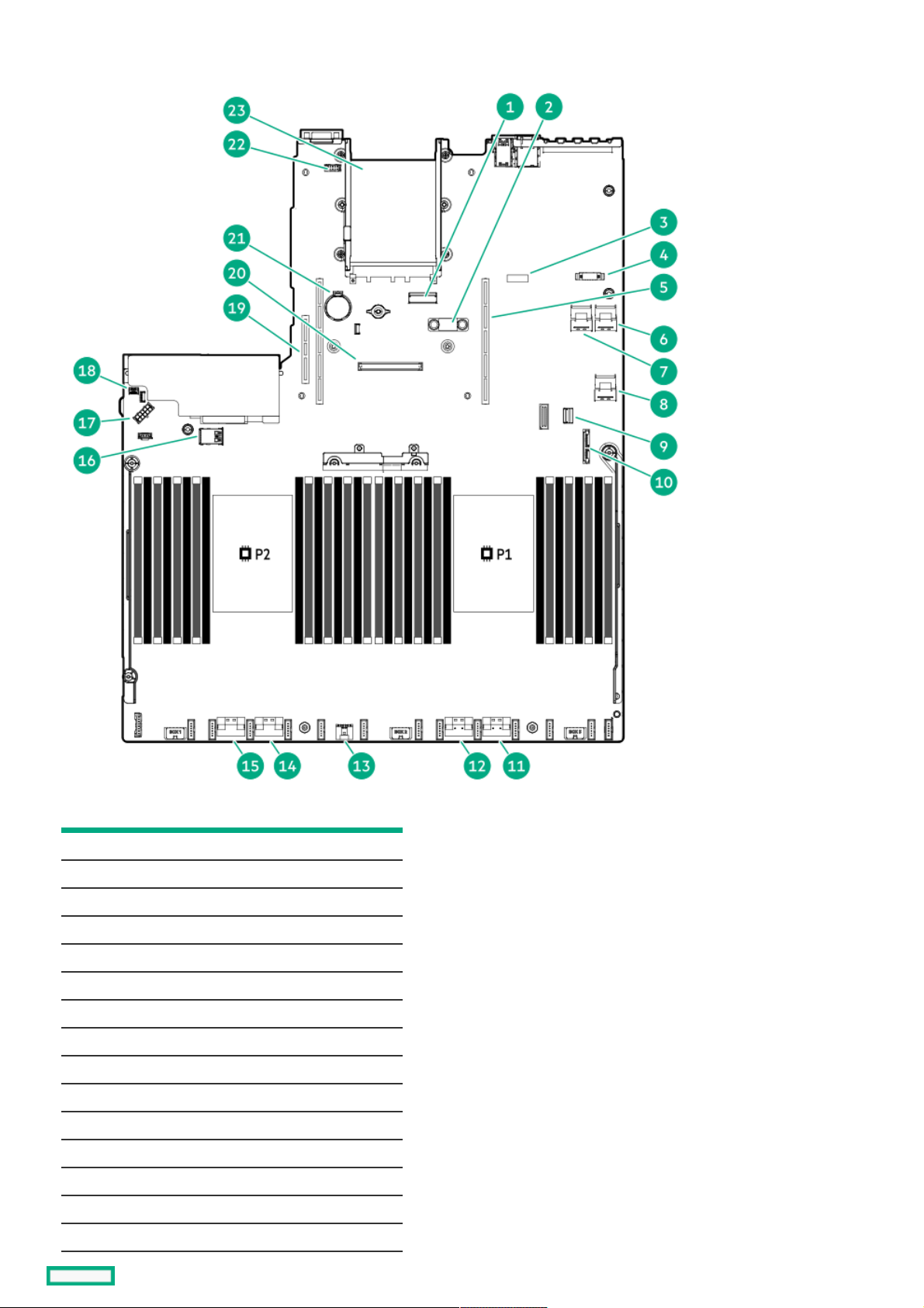
System board componentsSystem board components
ItemItem DescriptionDescription
1 x8 Slimline connector
2 TPM connector
3 System maintenance switch
4 Front display port/USB 2.0 connector
5 Primary (processor 1) PCIe riser connector
6 x4 SATA port 2
7 x4 SATA port 1
8 x2 SATA port 3
9 Front power/USB 3.0 connector
10 SATA optical port 4
11 x8 NVMe port 2A
12 x8 NVMe port 1A
13 Energy pack connector
14 x8 NVMe port 2B
15 x8 NVMe port 1B
System board components 20
Table of contents
Other Hewlett Packard Enterprise Network Storage Server manuals

Hewlett Packard Enterprise
Hewlett Packard Enterprise D2500sb Gen10 Manual

Hewlett Packard Enterprise
Hewlett Packard Enterprise HPE ProLiant DL385 Gen10 Plus User manual

Hewlett Packard Enterprise
Hewlett Packard Enterprise HPE ProLiant DL345 Gen10 Plus User manual

Hewlett Packard Enterprise
Hewlett Packard Enterprise 3PAR StoreServ 8 0A Series Assembly instructions


