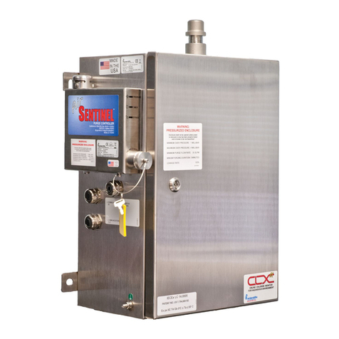
HF Scientific CLX-Ex User manual

OWNER’S MANUAL
CLX-Ex Online Residual
Chlorine Monitor
For Use in Explosive Environments
And Extended Reagent Life
Model 28031
HF scientific
3170 Metro Parkway
Ft. Myers, FL 33916
Phone: 239-337-2116
Toll Free: 888-203-7248
Fax: 239-332-7643
Website: www.hfscientific.com
Catalog No 28815B
Rev 1.5 (10/11)


Catalog #28815B (10/11)
REV 1.5
DECLARATION OF CONFORMITY
0359 II 2G Ex px IIC T4 Gb 0°C ≤ Ta ≤ 55°C
To the following standards:
Explosive Atmospheres –Part 0: Equipment –General Requirements, EN60079-0: 2009
Explosive Atmospheres –Part 2: Equipment Protection by Pressurized Enclosure “p”, EN60079-2: 2007
Emissions & Immunity –Tested and passed EN61326:1997 + A1:1998 + A2:2001 + A3:2003
Manufacturer’s Name: HF scientific inc.
Manufacturer’s Address: 3170 Metro Parkway, Fort Myers, Florida 33916-7597
Importer’s Name:
Importer’s Address:
Type of Equipment: Chlorine Process Monitor
Model No: CLX-Ex
I, the undersigned, hereby declare that the equipment specified above conforms to the above
Directive and Standard
Place: Fort Myers, Florida USA
(Signature)
Date: 1 June 2011 Rowan T. Connelly, General Manager


Table of Contents
Section Page
Specifications....................................................................................................1
1.0 Overview ...........................................................................................................2
1.1 Unpacking and Inspection of the Instrument and Accessories .............2
1.2 The Display ...........................................................................................3
1.3 The Touch Pad ......................................................................................3
1.4 Orientation ............................................................................................4
2.0 Safety.................................................................................................................5
2.1 Symbols Used In CLX-Ex .....................................................................5
2.2 Use in Explosive Environments Safety..................................................5
3.0 Theory of Operation ........................................................................................6
3.1 The Measurement...................................................................................6
3.2 The Purge Control X-Purge Controller..................................................7
3.3 Optional Remote Standby .....................................................................8
3.4 The Reagents .........................................................................................8
3.5 The Reagent Cooler ..............................................................................8
4.0 Installation and Commissioning ....................................................................9
4.1 Mounting & Site Selection.....................................................................9
4.2 Plumbing ............................................................................................10
4.3 Air Supply ..........................................................................................10
4.4 Electrical Connections ........................................................................11
4.4.1 RS-485 ...................................................................................11
4.4.2 Relays .....................................................................................11
4.4.3 4-20 mA ..................................................................................11
4.4.4 (Optional) Remote Standby Connections ................................12
4.4.5 RS-485/4-20 mA cable Ferrite.................................................12
4.5 Installing Reagents ..............................................................................12
5.0 Purge Control X-Purge Controller Operation ...........................................13
5.1 Start Up ...............................................................................................13
5.2 Indicator Lamp.....................................................................................13
5.3 Maintenance By-Pass Operation..........................................................14
6.0 Operation .......................................................................................................15
6.1 Routine Measurement .........................................................................15
6.2 Routine Measurement with Optional Remote Standby .......................15
6.3 Security Access Feature.......................................................................16
6.4 The White LED....................................................................................17
7.0 Instrument Calibration ................................................................................18
7.1 Slope (gain) Calibration Procedure .....................................................18
7.2 Zero (offset) Calibration Procedure ....................................................19
7.3 Restore Factory Settings ......................................................................19

Table of Contents (continued)
Section Page
8.0 Instrument Configuration (CONFIG mode) ...............................................20
8.1 Setting the 4-20 mA.............................................................................20
8.2 Configuring the Error Level.................................................................21
8.3 Configuring the RS-485 Port ..............................................................21
8.4 Configuring the Alarms .......................................................................21
8.4.1 Alarm1 .....................................................................................22
8.4.2 Alarm 2 ....................................................................................22
8.5 Enabling the Security Access...............................................................22
8.6 Extended Settings.................................................................................22
8.7 Units of Measurement..........................................................................23
8.8 Averaging and Filtering .......................................................................23
8.9 LCD Backlight Brightness...................................................................23
8.10 RS- 485 Parameters..............................................................................24
8.11 Cycle Time ..........................................................................................24
8.12 Water Conservation ............................................................................24
8.13 4 mA Adjustment.................................................................................25
8.14 20 mA Adjustment...............................................................................25
9.0 Additional Features and Options ................................................................26
9.1 RS-485 Output .....................................................................................26
9.1.1 Simple Communication ...........................................................26
9.1.2 Modbus Communication..........................................................26
9.2 Remote Panel Meter.............................................................................26
9.3 Desiccant Cartridge..............................................................................26
10.0 Troubleshooting .............................................................................................27
10.1 CLX-Ex Fault Detection ......................................................................27
10.2 Setting Flow Rate.................................................................................28
10.3 Clearing Faults .....................................................................................28
10.4 Reagent Clogs .....................................................................................28
10.5 Diagnostic Chart .................................................................................29
10.6 Technical and Customer Assistance ...................................................29
11.0 Routine Maintenance.....................................................................................30
11.1 Maintenance Schedule ........................................................................30
11.2 Replacing or Installing the Reagents ...................................................31
11.3 Indicator Reagent Preparation .............................................................31
11.4 Check Valve Flushing Kit ...................................................................34
11.5 Instrument Storage ..............................................................................34
11.6 Cleaning the CLX-Ex .........................................................................34
12.0 Accessories and Replacement Parts List .....................................................35
13.0 ATEX Certificate .........................................................................................36
14.0 Warranty .......................................................................................................39

CLX-Ex (10/11) Page 1
REV 1.5
Specifications
Measurement Range
0.00 –10.00 mg/L (PPM)
Accuracy
±5% of reading or ±0.03 mg/L (PPM) whichever is greater for range of
0-6.0 mg/L(PPM) ±10% of reading from 6.01-10.00 mg/L (PPM)
Resolution
0.01 mg/L (PPM)
Cycle Time
Adjustable; 110 seconds to 10 minutes (600 seconds)
Note: the system defaults to 2.5 minutes
Display
Multi-Line Liquid Crystal Backlit Display
Alarms
Standard: Two Programmable, 120-240VAC 2A Form C Relay
Remote Standby Option: One NO relay contact 120-240VAC 2A
Analog Output
Powered 4-20 mA, 600 drive, isolated
Communications Port
Bi-directional RS-485 with Modbus
Water Pressure
Integral pressure regulator 0.34 bar (5.0 PSI) to 10.3 bar (150 PSI.)
Flow Rate to Waste
200 –400 ml/min.
Operating Temperature
0°C –55°C (32°F –131°F)
Wetted Materials
PVC, Borosilicate Glass, Reslyn (FFKM), Viton®(FKM),
Polypropylene, 316 Stainless Steel, Acetal, Noryl®, Silicone
Sample Temperature Range
0°C –55°C (32°F –131°F)
Power Supply
240 VAC (130 to 240VAC), 47-63 Hz, 250VA
Insulation Rating
Double Insulated, Pollution Degree 2, Overvoltage Category II
Environmental Conditions
Not recommended for outdoor use.
Altitude up to 2000 meters
Up to 95 % RH (non-condensing)
ATEX Rating
0359 II 2G Ex px IIC T4 Gb 0°C ≤ Ta ≤ 55°C
Compressed Air
Water and oil free, -40oF (-40oC) Dew Point, Particles <5u, ISA Grade
Hydrocarbon Free. Full time clean dry air at 5.5 - 7 bar (80-101.5 PSI)
@20oC (68oF) Max
Regulatory Compliance
And Certifications
CE Approved, ETL listed to UL 61010-12004 &ETL certified to CSA
22.2 No. 61010.1 2nd edition dated July 2004
EN61326: 1997 + A1: 1998 + A2: 2001 + A3: 2003
Shipping Weight
38 kg (83lbs.) Reagents are Shipped Separately
Shipping Dimensions
558mm X 662 mm X 400mm (22” X 24 ½”X15 ¾”)

CLX-Ex (10/11) Page 2
REV 1.5
1.0 Overview
The CLX-Ex Online Chlorine Monitor allows for the reading of chlorine levels of process
water on-line. The CLX-Ex has been designed to meet the design criteria specified by
Standard Methods for the Examination of Water and Wastewater (21th Edition) Method
4500-Cl G. DPD Colorimetric Method. The CLX-Ex uses a 515nm LED as the
measurement light source.
This instrument has been designed to operate in explosive atmospheres and meets the ATEX
rating as stated in the specifications. The instrument does this with the use of an approved
purge/pressurization controller called Purge Control X-Purge. Please refer to the companion
manual Cat. No. 28815A for all information on:
Operation of the Purge Control X-purge.
Electrical power connections.
Purge Air Connection.
In addition this instrument has vortex cooling. This instrument will automatically control a
connected compressed air line to lower the temperature of one of the reagents, allowing the
reagent an operating life of up to 3 months.
Every effort has been made to ensure the accuracy of this manual. Due to the continuous
development and improvement of all instrumentation, there may be slight differences
between this manual and the instrument received. Therefore, no legal claims can be made
against any discrepancies herein.
1.1 Unpacking and Inspection of the Instrument and Accessories
The table below indicates the items in the shipment.
Item
Quantity
CLX -Ex Monitor
1
Instruction Manual
1
Tubing/Cuvette Kit: 8 black pump tubes, 2 different Cap Assemblies,
1 replacement cuvette
1
Check Valve Flushing Kit
1
Remove the instrument from the shipping crate. Carefully inspect all items to ensure that no
visible damage has occurred during shipment. If the items received do not match the order,
please immediately contact the local distributor or the HF scientific Customer Service
Department.

CLX-Ex (10/11) Page 3
REV 1.5
1.2 The Display
Figure 1 illustrates all the items that can appear on the display. The upper row of the
display (1) is used for reporting the chlorine levels and to provide user guidance in the
customer setting routine. The lower row of the display (2) is used to communicate error
messages (message queue) and provide user guidance. The display has two icons (3) that are
used to indicate the use of access code and offset mode. In addition, mode arrows (4) are
used to indicate the current instrument operating mode; AUTO (normal operation), CAL
(calibration) and CONFIG (configuration).
Figure 1: Display used in the instrument.
1.3 The Touch Pad
Figure 2 illustrates the touch pad. The touch pad has six buttons: PRIME, SERVICE,
MODE/EXIT,, and
The MODE/EXIT button is used to cycle between the three operational modes of the
instrument: CAL, CONFIG, and AUTO (Measurement) mode. The button enters the
option or mode that is highlighted or chosen. The and buttons are used to change
settings.
The PRIME and SERVICE buttons are dedicated controls. The PRIME will start 75
reagent pump pulses to prime the tubing after a change or addition of reagent bottles. The
SERVICE button will drain the instrument and hold all operations until either the
SERVICE button is pushed again or the power is reset. This button should be used while
changing the tubing, the measurement cuvette or reagent bottles.
Figure 2: The CLX-Ex touch pad.

CLX-Ex (10/11) Page 4
REV 1.5
VORTEX ASSEMBLY
PURGE
CONTROL
INLET WATER STRAINER
BUFFER REAGENT
BOTTLE
PUMP SOLENOID
OPTICAL BLOCK ASSY
MAIN CONTROL
CHASSIS
TEMPERATURE CONTROL
(UNDER FINGER GUARD)
WIRING COVER
REPLACEMENT
REAGENT CONTAINER
GROUND LUG
WATER REGULATOR
DRAIN AIR INLET & WATER INLET
WATER INLET
AIR INLET
POWER INLET
I/O SIGNALS
VENT ASSEMBLY
1.4 Orientation
From the diagram below the major components can be located. Note that two reagents are
required the buffer and the indicator. The reagents are discussed in the Routine Maintenance
section 10.0.
Figure 3: The CLX-Ex with Cover Open

CLX-Ex (10/11) Page 5
REV 1.5
2.0 Safety
This manual contains basic instructions that must be followed during the commissioning,
operation, care and maintenance of the instrument. The safety protection provided by this
equipment may be impaired if it is commissioned and/or used in a manner not described in
this manual. Consequently, all responsible personnel must read this manual prior to
working with this instrument.
In certain instances “Notes”, or helpful hints, have been highlighted to give further
clarification to the instructions. Refer to the Table of Contents to easily find specific topics
and to learn about unfamiliar terms.
2.1 Symbols Used In CLX-Ex
Standard IEC symbols are used on the high voltage cover.
ISO 3864, No. B.3.6 Caution, risk of electric shock.
This symbol indicates that hazardous voltages. This symbol is used in
this manual to bring attention to a potential electrical hazard
ISO 3864, No.B3.1 Caution refer to accompanying documents.
This symbol is reminding you to read the sections in the manual referring
to the electrical connections, and potential hazards.
This symbol is used to bring attention to a special feature or to provide
additional information.
2.2 Use in Explosive Environments Safety
In the interests of safety the operator must ensure the atmosphere where the instrument is
located is safe from gases, vapors, dust or other flammable conditions whenever the
instrument is opened for service or maintenance. At all other times the door must be kept
closed with purge air connected the purge system operating with the GREEN lamp lit
indicating safe operation.

CLX-Ex (10/11) Page 6
REV 1.5
3.0 Theory of Operation
3.1 The Measurement
The CLX-Ex has two solenoid valves, one for sample water (FLOW) and one for draining
of the cuvette (PURGE). A third solenoid, along with four check valves forms a reagent
pump. Sample water flow is controlled by the FLOW solenoid valve. The PURGE solenoid
valve is used to empty the cuvette in the measurement chamber.
The measurement chamber consists of a sample inlet, a purge drain, and an overflow. The
reagent is added from the check valves integrated into the lower portion. A green LED
provides the 515 nm source lamp, a red LED is used for sample level and flow
measurement. A single detector is located 180 º from the green LED. A replaceable glass
cuvette separates the LEDs from the detector and maintains the measurement path length.
Sample water flows in the inlet at the bottom, through the measurement cuvette and out
through an overflow drain. This flow is used to both fill the cuvette and flush the system.
The reagents are dispensed from two replaceable bottles. One bottle has a buffer to control
the pH; the second has an indicator that contains the DPD, which produces color when
chlorine is present in the sample. The degree of color is dependant on the amount of
chlorine in the sample water.
The measurement chamber is open to view operations. A white LED backlights the chamber
for a clearer view. The white LED will flash to attract attention in the case of a warning or
failure. Most warnings and failures are also displayed on the screen. To prevent interference,
the white LED is turned off during measurements.
During normal operation the CLX-Ex will run through a timed cycle. A simplified cycle
will consist of the following sequences:
Flushing –continuous sample flow
Purging –PURGE valve opens
Zeroing –no flow with cuvette full
Adding Reagents –one pulse of the reagent pump
Mixing with sample –sample flow pulses in
Reading resulting sample –no flow with cuvette full
Purging –PURGE valve opens to remove reacted sample
The cycle above is simplified and does not describe all the actions and testing that occurs.
The CPU continuously diagnoses the entire system for correct operation and sample water
flow. If an error occurs, a message is posted to the message queue on the LCD screen.
The reagent is added by a single pulse of the reagent solenoid. When the reagents require
replacement, the PRIME button is pushed to bring new reagents into the system. During
PRIME the reagent solenoid is pulsed several times to draw fluid from the two reagent
bottles and fill the tubes with new reagent. A complete PRIME takes less than a minute.
The SERVICE button empties the cuvette, stops the flow of sample water, and clears any
errors. This provides a convenient way to replace reagents and the measurement cuvette. If
more extensive servicing is performed, all power to the CLX-Ex should be removed. If the
CLX-Ex is to be turned off, it is recommended that the instrument be placed in SERVICE
mode before removing power. This ensures that the cuvette is emptied and the flow is off.

CLX-Ex (10/11) Page 7
REV 1.5
3.2 The Purge Control X-Purge Controller
The Purge Control X-Purge controller governs the power to the instrument. For normal
instrument operation air needs to passes through fitting on the base of the main enclosure
and constantly purge any vapors that could build-up. A SOLID GREEN lamp indicates a
safe operating condition. Only when this condition is reached will power be applied to the
measurement portion of the instrument.
Start-up
At start-up with the enclosure door open the Purge Control will display a RED lamp on the
visual indicator indicates that the system is not pressurized and no power is sent to the
instrument.
Closing the door with the air pressure applied, will cause the Purge Control to display a
FLASHING GREEN light. During this time the enclosure will undergo an automatic
dilution purge period of 5 minutes where at least 5 volumes of free space inside the
enclosure will be exchanged with clean purge air. No power is applied to the rest of the
instrument during this time.
After the enclosure air has gone through this purge period the Purge Control will display a
SOLID GREEN lamp. At this time the instrument is deemed safe and power is applied to
rest of the instrument.
WARNING: Do not apply power to the Purge Control X-Purge controller unless the
area has been properly tested and is known not to contain explosive materials.
By-Pass Key
WARNING: Use of the by-pass key disables the safety features and safe operation of
this instrument. It is imperative that this operation be performed only after the area
has been tested and known to be safe.
Assuming the area has been tested and is known not to contain explosive materials; a by-
pass service key is provided and can be used. In this operating mode power will be retained
to the rest of the instrument even though the door is open. It is imitative that this mode is
only used after area is known to be safe. This operation disables the safe operation of this
instrument.
Upon turning the key, the indicator will display a FLASHING RED lamp. This is an
indication of the maintenance mode. Power is retained to the instrument. The key cannot be
removed in this mode of operation.
After maintenance has been performed the door should be closed and latched. Air pressure
will once again pressurize the enclosure. The maintenance key can now be turned and
removed and the key cover replaced. The purge controller will display a SOLID GREEN
lamp indicating a safe operation and power is kept applied to the instrument.

CLX-Ex (10/11) Page 8
REV 1.5
Warning: no direct air connection should be made to the Purge Control X-Purge
Controller.
3.3 Optional Remote Standby
This factory installed option will allow for remotely placing the instrument into a standby
mode. This can be done to lower reagent usage while not performing ballasting or de-
ballasting operations. The last operation of each cycle is a flush and hold. Whenever the
instrument not being used (standby), it is stored such that the optics is clean & dry.
Dry contact are provided as feedback as to the operation of the instrument (operating or
standby). For more information on this option refer to sections 4.3.5 (Optional) Remote
Standby Connections and 6.2 Routine Measurement with Optional Remote Standby.
All connections that carry power not generated inside the CLX-Ex, with the exception
of the mains, must be connected through Intrinsic Safety Barriers.
3.4 The Reagents
The indicator reagent reacts with any oxidant, generally chlorine, to create a pink color
which the instrument measures and compares with a sample of water without reagents.
The buffer reagent is required to control the sample pH to bring the sample to neutral.
The reagents are provided already hydrated and require little operator preparation.
The indicator reagents are packaged a plastic box. Each 125 mL indicator will require the
addition and mixing of the DPD powder contained in the small brown bottle. This activates
the indicator reagent. The indicator reagents should be changed out on a 90 day basis even if
they are not fully used.
The 500 ml buffer does not require any preparation and is good for one year.
After one year all the reagents will have been consumed and replacement reagent set will be
required. This can be ordered through agent Catalog No.09991. This set will include a new
plastic box with four sets of Indicator reagents plus one 500 mL bottle of Buffer.
3.5 The Reagent Cooler
A reagent cooler is provided for the 125 ml indicator reagent.
For proper operation power must be applied by the Purge Control X-Purge controller to the
cooling chamber temperature controller. Clean dry compressed air must also be provided at
pressures between 5.5 and 7 bar (80 to 101.5 PSI).
The cooling chamber temperature controller governs the solenoid which controls air flow to
the vortex cooling unit. The air flow is turned on or off as required to maintain the
indicating reagent temperature at 20-25˚C. This extends the life of the reagent up to 90 days.
To provide this extended reagent life, power to the cooling power supply and air pressure
must be supplied full time.

CLX-Ex (10/11) Page 9
REV 1.5
4.0 Installation and Commissioning
Prior to use for the first time, one of the reagents (the indicator) will have to be mixed. Refer
to section 11.2 Replacing or Installing the Reagents.
4.1 Mounting & Site Selection
The instrument is designed for wall mounting. Choose a location that is easily accessible for
operation and service and ensure that the Purge Control lamp is about eye level.
Consideration must be made for the plumbing and electrical conduit connections. The
overall mounting dimensions of the instrument are shown in Figure 4.
15.280 [388.10]
15.623 [396.81]
27.355 [694.81]
18.660 [473.95]
.750 [19.05]
8.324 [211.42]
9.433 [239.60]
1.997 [50.72]
2.875 [73.02]
4.333 [110.06]
8.290 [210.57]
2.000 [50.80]
2.750 [69.85]
2.650 [67.31]
2.500 [63.50]
POWER IN
SIGNAL I/O
DRAIN FOR 12 MM O.D. SS TUBING
WATER INLET FOR
6 MM O.D. SS TUBING
AIR INLET FOR 6 MM O.D. SS TUBING
Figure 4: Overall Mounting Dimensions of the Instrument

CLX-Ex (10/11) Page 10
REV 1.5
Be sure that the instrument be mounted as close as possible to the sampling point to ensure a
quick response time (within 2-3 meters (6-10 ft) of the sampling point).
4.2 Plumbing
The instrument is designed to require very little head pressure to operate, but will need
around 0.34 bar (5 PSI). The maximum pressure for proper operation should not exceed
10.3 bar (150 PSI). The maximum allowable fluid temperature is 55°C (131°F).
The fluid waste from drain connection of this instrument contains reagents with large
quantities of sample water. HF scientific recommends that operators check with local
authorities concerning proper disposal of waste diluted fluids. This waste fluid must
NEVER be reintroduced into the incoming water stream.
All plumbing connections are intended to be made through stainless steel connections.
The water sample inlet requires 6 mm OD stainless steel tubing. The fitting is a compression
fitting so the installer need only place the supplied the nut and feral over tubing and tighten.
The water drain requires 12 mm OD stainless steel tubing. This fitting is also a compression
fitting so the installer need only place the supplied the nut and feral over tubing and tighten.
Properly installed and sealed connections are required to ensure the water tightness and
ratings of the instrument.
4.3 Air Supply
This instrument requires water and oil free air, -40oF (-40oC) Dew Point, Particles <5u, ISA
Grade Hydrocarbon free. The air needs to be provided at between 5.5 and 7 bar (80-101.5
PSI) with a volume of 4 cubic foot/min as measured at 80 PSI. This air supply must be
provided continuously from a known safe area. Min flow is 25 SCFH.
The air connection requires 6 mm stainless steel tubing. A compression type fitting is
supplied on the base of the main enclosure that simply requires the installer to slip the
supplied nut and feral over the tubing and then tighten the nut.
Warning: No direct air connection should be made to the Purge Control X-Purge
Controller.

CLX-Ex (10/11) Page 11
REV 1.5
4.4 Electrical Connections
All electrical connections must pass through the three compression grommets on the left
side of the instrument. Cabling must be selected to ensure that these connections are tight.
The grommets can accept cabling from 9 to 17 mm diameter. One grommet is supplied for
system power and two are supplied for low voltage I/O connections. These grommets must
be tightened to maintain cabinet air pressure.
The electrical power for the protective gas supply (blower, compressor, etc.) should be
either taken from a separate power source or taken from the supply side of the electrical
isolator for the pressurized enclosure.
Most of the low voltage electrical communication connections to the instrument are made at
the termination area which is located on the left side of the instrument. Remove the access
cover by loosening the captive screw. The connections are labeled and are self-descriptive.
Please follow all government recommendations for installation of electrical connections to
and between the instrument and other peripheral devices.
All terminals are designed to accept wires in the range of 14-28 AWG. All wires should be
stripped to a length of 6 mm (¼”).
Note: For line power connections refer to the companion manual Catalog No. 28815A
4.4.1 RS-485
The RS-485 half-duplex (2-wire) digital interface operates with differential levels
that are not susceptible to electrical interferences. This is why cable lengths up to
3000 ft can be implemented. The last device on each bus may require terminating
with a 120 ohm resistor to eliminate signal reflection on the line. Do not run RS-485
cables in the same conduit as power. Set-up of the RS-485 is covered in 8.3
Configuring the RS–485 Port
To prevent damage to the instrument, ensure that
power is disconnected prior to making connections.
For ease of connecting, remove the plug-in terminal
block. Connections are labeled beside this
termination on the PC board. The recommended
cable is 22 AWG shielded twisted pair. The grey
terminal block is removable to assist in making
connections.
4.4.2 Relays
Two C-Form relay alarm connections labeled
Alarm 1 & Alarm 2 are provided for user
connections these are labeled as NO (Normally
Open), C (Common) and NC (Normally Closed).
Please note that these are fail-safe so the “normal”
condition is power to the CLX-Ex on and no alarm
condition. The relays are rated 240VAC 2A.
Operation of these alarms is covered in section 8.4
Configuring the Alarms.

CLX-Ex (10/11) Page 12
REV 1.5
The Remote Standby option reduces the Relay connections to a single relay contact
labeled NO (Normally Open) and C (Common).
4.4.3 4-20 mA
The 4-20 mA output is driven by a 15 VDC power source and can drive recorder
loads up to 600 ohms. Transformer isolation is provided on the CLX-Ex. Do not run
4-20 mA cables in the same conduit as power. Operation of this output is covered in
section 8.1 Setting the 4-20 mA.
To prevent damage to the instrument, and for general safety ensure that power is
disconnected to the CLX-Ex prior to making any connections. Polarities of the
connections are labeled beside this termination on the PC board.
The recommended cable is 22 AWG shielded twisted pair. To prevent ground loops,
connect the shield at either the CLX-Ex or at its destination, but not both. The grey
terminal block is removable to assist in making connections.
The 4-20mA is factory calibrated. An adjustment is available on the 4-20mA in
sections 8.12 and 8.13. In addition to making adjustments, these menus output
continuous 4 mA or 20 mA and can be used as a signal test. Remember that the
configuration mode will timeout after 15 minutes.
4.4.4 (Optional) Remote Standby Connections
This option the instrument operates on user control software, where an external
control initiates each cycle. This control line is called the RSI short for Remote
Standby Input.
The CLX-Ex will indicate the current status on another line called RSO or Remote
Standby Output. These are a relay contact that is open when busy and open during
when in standby mode.
The connections are labeled RSI and RSO. The RSI has + and –polarity connection
associate with it and expects a 24V dive signal.
The RSO is simply relay contact connections and is not polarized.
Be sure to install Intrinsic Safety Barriers on both RSI and RSO control lines back at
the PLC or control device located in a safe area.
4.4.5 RS-485/4-20 mA cable Ferrite
To meet IEC requirements for RF radiated immunity a clamp-on type ferrite is
supplied in the accessory kit. It should be placed on the RS-485 or 4-20 mA cable
outside, as close as possible to the CLX-Ex. If both outputs will be used, an
additional ferrite will be needed and can be ordered from HF scientific Catalog
number 24560T.
4.5 Installing Reagents
The CLX-Ex will require that two reagents be installed prior to operation. These are a buffer
and an indicator. For reagent preparation refer to section 11.2 Replacing and Installing the
Reagents.

CLX-Ex (10/11) Page 13
REV 1.5
5.0 Purge Control X-Purge Controller Operation
The Purge Control X-Purge controller is mounted on the side of the main enclosure. This
controller will ensure proper safe operation of the CLX-Ex. If of all the required conditions
are met, the controller will act as a power governor. It does this by monitoring the
pressurization of the main enclosure with clean dry air. Should this air supply pressure fail
the indicator lamp on the Purge Control X-Purge unit will turn RED and power to the rest of
the instrument is disconnected.
WARNING: Do not apply power to the Purge Control X-Purge controller unless the
area has been properly tested and is known not to contain explosive materials.
5.1 Start Up
When power is applied to the CLX-Ex for the first time, ensure that the air supply is
connected as stated in section 4.3 and the cabinet is closed and locked. Once power is
applied, the Purge Control X-Purge will go through a purge period of 5 minutes where at
least five volumes of the enclosure are pushed through the CLX-Ex and out the vent at the
top of the instrument. During the purge period the indicator lamp mounted on top of the
Purge Control X-Purge will flash GREEN indicating the purge is in process and no power is
applied to the rest of the CLX-Ex.
At the complete of the purge, indicator lamp will go solid GREEN and power will be
applied to the rest of the system. As long as the proper air supply conditions are met the
CLX-Ex will continue to operate.
5.2 Indicator Lamp
The indicator lamp is a very quick way to determine to operation of the controller and thus
the safety condition of the CLX-Ex.
Lamp Color
Meaning
Power to rest of CLX-Ex
Solid GREEN
Safe Operation
Power ON
Flashing Green
Instrument purging
Power OFF
Solid RED
Unsafe Operation
Power OFF
Flashing Red
By-Pass Key Operating
Power ON
NO Lamp
No power applied to CLX-Ex
No power applied everything off.
Using the table above, you can quickly determine the operating condition of the instrument.
Under normal operation a solid GREEN lamp should appear.

CLX-Ex (10/11) Page 14
REV 1.5
5.3 Maintenance By-Pass Operation
WARNING: Use of the by-pass key disables the safety features and safe operation of
this instrument. It is imperative that this operation be performed only after the area
has been tested and known to be safe.
To perform some maintenance operations on the CLX-Ex it is necessary to have the entire
instrument powered up while the enclosure door is open. Under these conditions normally
the Purge Control X-Purge controller would determine that the enclosure is not pressurized
and power will be removed to the measurement section of the CLX-Ex. To allow for this
situation, a special maintenance by-pass key is supplied.
Located on the right side of the Purge Control X-Purge controller is a hex cap. Removing
this cap reveals the key slot. Insert the key and turn it clockwise to engage the bypass
operation. The indicator lamp will flash Red to indicate the by-pass mode. Assuming the
area around the CLX-Ex has been tested and known to be safe, the enclosure door can now
be safely opened and power will remain on to the entire system. The key cannot be removed
while operating in the maintenance by-pass mode.
WARNING: Do not operate the CLX-Ex for long periods of time in the by-pass mode.
This is intended only for maintenance operations.
WARNING: Do not operate the CLX-Ex in the by-pass mode unattended.
To return the instrument to normal, safe operation, close the enclosure door. Ensure that the
air supply is connected turn the key counter-clockwise and remove. Replace the hex cover.
If the pressure in the cabinet has built up to a normal acceptable level the lamp will show
solid GREEN and the system will continue to run.
Other manuals for CLX-Ex
1
This manual suits for next models
1
Table of contents
Other HF Scientific Measuring Instrument manuals
