GeoSIG AC-73-DH Installation and operating instructions

GeoSIG Ltd, Wiesenstrasse 39, 8952 Schlieren, Switzerland
Phone: + 41 44 810 2150, Fax: + 41 44 810 2350
User Manual & Installation Guide
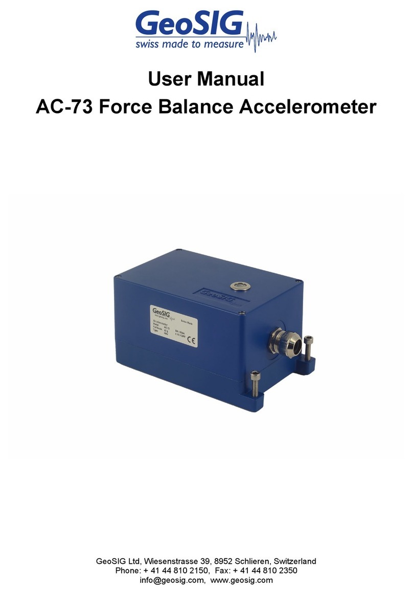
AC-73-DH Force Balance Accelerometer

User Manual & Installation Guide AC-73-DH Force Balance Accelerometer
2 / 20 13.04.2021 / V3.9
GS_AC-73-DH_UserManual+InstallationInstructions_V03.docx
Document Revision
Rev
Description
Prepared by
Checked by
Approved by
Date
3
Changes from SI_31592
CUE
KEC
TAB
2021-04-09
2
text corrections/improvements
SER
TAB
JOG
2015-03-31
1
Pinout correction of iSensor
MAE
SER
TAB
2013-11-12
0
First issue
SER
MAE
TAB
2013-11-05
File name:
GS_AC-73-DH_UserManual_V03.docx
Project:
AC-73-DH
Title:
User Manual & Installation Guide
CUSTOMER
Disclaimer
GeoSIG Ltd reserves the right to change the information contained in this document without notice. While the information contained
herein is assumed to be accurate, GeoSIG Ltd assumes no responsibility for any errors or omissions.
Copyright Notice
No part of this document may be reproduced without the prior written consent of GeoSIG Ltd. Software described in this document is
furnished under a license and may only be used or copied in accordance with the terms of such a license.
Trademark
All brand and product names mentioned are trademarks or registered trademarks of their respective holders.
All rights reserved.
GeoSIG Ltd
Switzerland

User Manual & Installation Guide AC-73-DH Force Balance Accelerometer
13.04.2021 / V3.93 / 20
GS_AC-73-DH_UserManual+InstallationInstructions_V03.docx
Table of Contents
Warnings and Safety...........................................................................................................4
1. Introduction......................................................................................................................5
2. Pre-installation.................................................................................................................5
2.1. Preparation check list..............................................................................................................................7
2.2. Borehole and Casing...............................................................................................................................7
2.3. Materials and tools for installation...........................................................................................................8
2.3.1. Construction Materials.....................................................................................................................9
2.4. Unpacking and handling of the sensor....................................................................................................9
3. Installation .....................................................................................................................10
3.1. Grouting.................................................................................................................................................10
4. Reference......................................................................................................................11
4.1. Specifications........................................................................................................................................11
4.2. Description ............................................................................................................................................12
4.3. Sensor physical dimensions..................................................................................................................13
4.4. Sensor interface....................................................................................................................................14
4.5. Connection............................................................................................................................................14
4.6. iSensor interface ...................................................................................................................................15
4.6.1. Preparation ....................................................................................................................................15
4.6.2. Installation of the Software ............................................................................................................16
4.6.3. Simple User Interface ....................................................................................................................16
4.6.4. Compass Calibration .....................................................................................................................18
4.6.5. Expert Mode...................................................................................................................................18
5. Maintenance..................................................................................................................20
5.1. Testing...................................................................................................................................................20
5.1.1. Test input.......................................................................................................................................20
5.1.2. Power.............................................................................................................................................20
5.1.3. Offset .............................................................................................................................................20
5.1.4. Gain ...............................................................................................................................................20
5.1.5. Noise..............................................................................................................................................20
5.2. Calibration.............................................................................................................................................20

User Manual & Installation Guide AC-73-DH Force Balance Accelerometer
4 / 20 13.04.2021 / V3.9
GS_AC-73-DH_UserManual+InstallationInstructions_V03.docx
List of Figures
Figure 1. Typical Installation Layout (not to scale) ............................................................................................ 6
Figure 2. Typical Installation of Casing (not to scale)........................................................................................ 8
Figure 3. Sensor view........................................................................................................................................ 9
Figure 4. Block diagram................................................................................................................................... 12
Figure 5. Sensor housing dimensions ............................................................................................................. 13
Figure 6. Overview of cabling.......................................................................................................................... 15
Figure 7. Detailed cabling................................................................................................................................ 16
Figure 8. CSV file opened in the Microsoft Excel............................................................................................ 17
List of Tables
Table 1. Estimation of Construction Material Quantity ...................................................................................... 9
Table 2. AC-7x-DH Basic Specifications ......................................................................................................... 11
Table 3. AC-7x-DH Cable Wire Assignment and Colour Code ....................................................................... 14
Warnings and Safety
a
The sensor housing provides no protection against explosive atmosphere. It must not be directly
operated in an area where explosive gases are present.
In case of any doubt about the installation, please contact GeoSIG for advice.

User Manual & Installation Guide AC-73-DH Force Balance Accelerometer
13.04.2021 / V3.95 / 20
GS_AC-73-DH_UserManual+InstallationInstructions_V03.docx
1. Introduction
This document describes the steps needed for the installation of GeoSIG AC-7x-DH series down-hole
accelerometers, including some guidelines for the borehole drilling.
Such installation procedures / instructions always require to be reviewed according to the local situation and
must be used as guidelines only.
The AC-73-DH is an accelerometer sensor that covers the full range for strong-motion measurement over the
required amplitude and frequency ranges. For a detailed description of the sensor and its interface, please
refer to section 4.
The reasons to have a borehole sensor instead of a sensor at surface can be:
To measure the acceleration at the rock level without the influence of sediments or soft soil.
To define site condition to know amplification factor. The acceleration level at surface can be
measured with a simple sensor such as AC-73 and with borehole measurement where the
amplification factor can be defined. This factor is highly dependent on local conditions and can vary
to a great extent from one location to another.
To avoid human induced noise present at surface.
2. Pre-installation
A good understanding of the installation requirements is the basis for a successful and reliable sensor
installation and good quality measurement. As a first requirement, the parameters of the borehole should be
well defined. For the requirement related to the sensor itself, the requirements can be simply summarised as
below:
Free borehole diameter of 100 mm as a minimum (larger when casing is installed).
Water level above the sensor in the borehole should never be more than 100 meters. At installation,
water level should be less than 50m to allow for rising water level during rain.
In cases where there is water in the hole, combination of the chemical compositions and temperature
should be evaluated for compatibility with the sensor housing material. This usually concerns
installations located in areas with hot springs or near volcanoes.
A casing may be installed in the borehole. The decision depends mainly on the kind of rock to be
bored. The point of the casing is only to provide integrity to the borehole during installation, which
typically lasts several weeks. The casing has no effect on the sensor or signal during operation.
The selection of the casing type has an influence on how the orientation of the sensor after insertion
in the borehole can be defined. The sensor has an internal compass (toward magnetic North) to
define the orientation of its X/Y axes relative to magnetic North. Its measurement will be only valid if
no casing or non-magnetic material is used (plastic, aluminium, fibre glass casing). In case of steel
casing, the orientation of the sensor should be calculated using some recorded earthquakes (or
explosion data at a known azimuth) and a reference surface sensor at borehole top.
In the following page, an overview of the layout of a typical installation is provided.

User Manual & Installation Guide AC-73-DH Force Balance Accelerometer
6 / 20 13.04.2021 / V3.9
GS_AC-73-DH_UserManual+InstallationInstructions_V03.docx
Figure 1. Typical Installation Layout (not to scale)
About 50 cm
100 m maximum
About 50 cm
About 250 cm
Cementation of
sensor. At least 1
meter above the
sensor.
AC-73-DH sensor
torpedo, diameter
8.9 cm.
Sand (>50 cm)
Water level above
the sensor
Cable and
supporting steel wire
Recommended sand
backfill to surface
Top cap/box to avoid
water ingress

User Manual & Installation Guide AC-73-DH Force Balance Accelerometer
13.04.2021 / V3.97 / 20
GS_AC-73-DH_UserManual+InstallationInstructions_V03.docx
2.1. Preparation check list
The following should be prepared before installation:
Drawing of site implementation, including cable length.
Installation of sensor recorder.
Drilling of the borehole.
Installation and cementation of the borehole casing, if applicable.
Verification of the borehole, depth of the water level and the path in the hole is free for the sensor. See
Section 2.2.
Preparation of wire lowering device and top cap/box, if applicable
Trench/conduit for routing of signal cable from top of borehole to recorder. Under-ground routing is
preferred.
2.2. Borehole and Casing
The borehole must either have a casing (e.g. steel or PVC) or adequate steps must be taken to protect the
integrity of the borehole walls and avoid ground material falling in the hole before the sensor can be installed
and grouted.
If the hole is lined with a casing, cement must be injected in the annular region between the casing
and borehole wall, generally over the full height of the casing. Generally, one week delay should be
allowed for curing of the cement.
For drilling depths of more than 20 meters, the drill diameter (or internal casing diameter) must be at least
12 cm to ensure the sensor reaches the full depth. For holes of less than 20 meters, a drill diameter (or internal
casing diameter) of 10 cm is sufficient. Where injection tubes are used for grout, this diameter must be selected
allowing for space to run the injection tube and/or reasonable grout flow around the sensor to avoid a cavity
below the torpedo.
The deviation of the hole must remain within the following specifications to ensure clear installation of the
sensor torpedo, as well as preserve the alignment of signal axes:
The deviation drift must remain below ±1° / 3 meters
The deviation at sensor location should be within ±3°, the maximum recommended deviation is ±9°
from vertical.
For plastic casing (e.g. PVC), some water may need to be added to the inside to avoid buoyancy and pressure
difference at the bottom of the borehole. Otherwise, there is the risk that the casing can break.
It is highly important that the cementation at the bottom of hole is as solid as possible to ensure a
good coupling near the level of the sensor. So injection should be performed first from the bottom. An
injection plastic tube should be routed along the casing when it is inserted in the hole. If the injection
cannot be fully performed from the bottom, the rest of injection should be done from the top.
If possible, the cementation should be verified within the next 24 hours using ultrasonic measuring
equipment or measuring the temperature profile in the hole. For both methods, water must be present
in the hole.
Downhole sensors that are encased in concrete are not retrievable in case of failure. In the unlikely scenario
that a failed downhole sensor must be replaced, it is not recommended to install the spare sensor in the same
borehole, on top of the original sensor. For some installations, it can be useful to install and cap 1 or 2 additional
boreholes during the initial boring, such that a spare sensor can be installed immediately, if required.

User Manual & Installation Guide AC-73-DH Force Balance Accelerometer
8 / 20 13.04.2021 / V3.9
GS_AC-73-DH_UserManual+InstallationInstructions_V03.docx
Figure 2. Typical Installation of Casing (not to scale)
2.3. Materials and tools for installation
In addition to a common set of basic tools, the following tools and materials are required. Items to be provided
by GeoSIG as part of the BOM include:
Sensor torpedo with integral cable and suspension wire loop;
Junction Box at the top of the borehole, if applicable;
Associated recorder for the sensor (e.g. GMSplus or SMS Recorder).
Tools provided by GeoSIG for installation (see Section 4.6):
Laptop (Windows based) to run GeoSIG utility for iSensor interface (iSensorUI.zip);
A serial adapter for RS-485 like MOXA TCC-80I to interface the laptop serial port (or through a USB
adapter) with the RS-485 interface of the sensor.
Items to be provided by customer or subcontractor include:
Depth probe with water level indicator to know the real depth of the hole;
Steel wire for sensor suspension with the appropriate lock nut for the depth of the hole plus an
additional length of at least 10 meters. Typically stainless steel wire 3 mm diameter with a capacity of
up to 100 kg;
Grout injection tube to be fixed along the steel wire and on the side of sensor (provided there is enough
space);
A fixation point at the surface close to the borehole for the steel wire;
Construction materials as listed in Section 2.3.1.
Drilling depth
Cap
Casing
cementation
Casing
Internal free
diameter at least
10 cm
>10 cm
Surface level
Casing extends ~20cm
above ground surface to
avoid water/earth ingress

User Manual & Installation Guide AC-73-DH Force Balance Accelerometer
13.04.2021 / V3.99 / 20
GS_AC-73-DH_UserManual+InstallationInstructions_V03.docx
2.3.1. Construction Materials
Sand and concrete are necessary for the installation of the sensor and/or casing. This includes:
Annular cementation between the casing and borehole (if applicable; Section 2.2)
Sand cushion for the sensor (0.5-1.0m)
Cementation of the sensor (see Section 3.1)
Sand backfill
External hole or casing
diameter [cm]
Volume between hole and tube
[dm3/ meter]
Volume of sensor
[dm3]
10
8
3.2
12
11.3
3.2
15
17.7
3.2
Table 1. Estimation of Construction Material Quantity
With: Volume [dm3], Diameter [cm]
Cement mix is required to have sand, bentonite and cement. The quantities should be evaluated according to
the diameter of the hole, the depth and the mixture requirement outlined in Section 3.1.
If the installation does not utilize a casing, there must be an extra reserve for cementation of the sensor inside
the borehole as there could be cavities in the earth that require additional volume of cement.
2.4. Unpacking and handling of the sensor
The accelerometer is precision measurement equipment and should be handled with care. Although the sensor
is designed and manufactured to be strong for its class, drop shock with hard surfaces should be avoided.
Due to its long cylinder shape, when the sensor is placed on its base, there is a risk that it may fall. It is
recommended that it is stored on its side, however care should be taken that it doesn’t start rolling and fall
from the surface it is placed on.
Figure 3. Sensor view
40
2
Diameter
Volume
Cable entry
Ring for suspension (2)
U shape wire to connect
to suspension wire
Sensor housing

User Manual & Installation Guide AC-73-DH Force Balance Accelerometer
10 / 20 13.04.2021 / V3.9
GS_AC-73-DH_UserManual+InstallationInstructions_V03.docx
3. Installation
1. iSENSOR
a. Make sure the communication with the iSensor is working as described in chapter 4.6.
b. Perform a compass calibration as described in chapter 4.6.4.
2. SENSOR TORPEDO
a. Verify water level in borehole, if applicable
b. Deposit the equivalent of at least 50 cm of sand (see section 2.3.1 for the volume) in the
borehole/casing.
c. Gently bind the sensor cable about every 3 meters to the suspension wire, ensuring that
the cable will not kink or strain. The sensor cable is not made to support the weight of the
sensor and cable.
d. If applicable, fasten the grout injection tube to the side of the sensor torpedo.
e. Lower the sensor in the casing/borehole until it reaches the sand at the bottom, when the
suspension wire becomes slack. The movement should be controlled using the steel wire.
The sensor cable and cement injection tube should be free of tension.
f. Lift the sensor up by 50 cm so it is suspended by the wire (to ensure it is in a vertical
orientation). See Figure 1.
g. Connect the cable to the junction box at top of borehole (if applicable).
3. INSTRUMENTATION
a. Route the cables from the borehole (junction box or integral cable) to the recorder.
b. Perform a sensor test from GeoDAS or from the recorder console.
c. Test the whole system.
d. A continuous monitoring of the system pre-grout should be performed for a few days. This
ensures the operation/reliability of the sensor (e.g. no water ingress).
e. A longer period of pre-grout monitoring can also be used to ensure that the location of the
sensor suits the customer requirements with regards to noise level or seismic transfer
function to a reference sensor. In this case, it is recommended to temporarily fix the sensor
in place with sand or glass beads.
4. GROUTING
a. Final cementation/grouting of the sensor in the borehole/casing (see Section 3.1).
b. When the cementation is complete (e.g. after curing), sand should be deposited in the
borehole –preferably to the surface –to avoid that the cable and steel wire can sway in
case of earthquake and create triboelectric (parasitic) signals.
c. Release of steel wire.
It is not recommended to perform the cementation of the sensor in the borehole/casing right after its
insertion. The whole installation should be finished and the system should run for several weeks and
show correct operation before the final cementation of the sensor inside the hole is performed.
Care must be taken with the cable to avoid kinking, cutting or abrasion of the cable jacket, which can
lead to water ingress and sensor failure. Always maintain the minimum bending radius of >180mm.
3.1. Grouting
After the sensor has been successfully tested in its place, the cavity between borehole/casing and the sensor
can be grouted. Inject a grouting mixture consisting of 100 liters of water, 50 kg of cement, and 10 kg of
bentonite. The bentonite percentage may be increased or reduced according to the consistency of the
examined soil and water content). It must be liquid enough that it will not form a cavity under the torpedo. Use
low pressure and low flow for the expected required amount of the mixture. The grout should be cured within
one week. Backfill the rest of the internal cavity with sand, if applicable, and add a top cap, if applicable. Note
sensor cable minimum bending radius at casing exit. Perform additional noise measurements after completion.

User Manual & Installation Guide AC-73-DH Force Balance Accelerometer
13.04.2021 / V3.911 / 20
GS_AC-73-DH_UserManual+InstallationInstructions_V03.docx
4. Reference
The AC-73-DH sensor package is a true electro-mechanical triaxial down-hole accelerometer designed for
earthquake monitoring and applications requiring highly sensitive and ruggedized sensors with minimum
maintenance and a simple method for periodic testing. The core of this accelerometer is based on the same
electronics used in AC-73 or AC-73i with the same performance. The housing for the AC-73-DH is made for
insertion into a borehole with a diameter of 100 mm or higher. The orientation of the sensor in the hole can be
defined either by the integrated compass (accessible over the iSensor interface) or by calculation using the
azimuth of recorded known earthquakes and the borehole location.
4.1. Specifications
The key specifications of the sensor are in the table below. For more detailed specifications, please refer to
the AC-73-DH leaflet.
Sensor P/N
AC-7x-DH
Input range
Acceleration, ±0.5, ±1.0, ±2.0, ±3.0 or ±4.0 g
Output range
0 ± 10 Volt differential output (20 Vpp)
Frequency range
DC to 200 Hz
iSensor
Digital monitoring of sensor condition accessible through RS-485 interface, it
provides the following information:
Temperature inside sensor
Humidity inside sensor
Tilt along X and Y axis
Orientation to magnetic North
Protections
All connector pins are over-voltage protected by double stage circuit
Power supply
9.5 –18 VDC
Current drain
Typical 80 mA @ 12 VDC
Dimensions
Diameter 89 mm x 502 mm (excluding screws and cable entry)
Housing Material
Stainless Steel (Austenitic) - EN 1.4401/14404 (AISI 316/316L)
Volume
3.2 dm3
Weight
4.2 kg
Density
1.3 kg/dm3(No additional weight needed for insertion in borehole with water)
Table 2. AC-7x-DH Basic Specifications

User Manual & Installation Guide AC-73-DH Force Balance Accelerometer
12 / 20 13.04.2021 / V3.9
GS_AC-73-DH_UserManual+InstallationInstructions_V03.docx
4.2. Description
The rugged mass suspension moving coil system improves the signal to noise ratio. The magnetic system and
capacitive position sensors offer symmetrical controls for the accurate electronic centring of the mass. At rest
the accelerometer mechanism is in balance and no electrical output is generated. Acceleration applied to the
AC-73-DH will result in an electrical output proportional to the current used to keep the mass centred. This
accelerometer output signal is calibrated to “g” gravity so that the current scale factor of the AC-73-DH is in
units of milliamps per g. Because of the symmetrical positioning system incorporated with the force balance
servo accelerometer principle, the accelerometer cannot arbitrarily change its scaling or drift out of calibration.
The sensor interface to the recording system is based on a differential voltage for each axis over 2 twisted
wires (twisted pair) to avoid disturbance over long distance.
The AC-73-DH is equipped with electronic offset adjustment features that keep the offset low and make its
installation very user friendly. This powerful feature allows the users to install the AC-73-DH without
mechanical offset adjustment. Additionally, no fine levelling is necessary and the sensor can easily adapt to
typical deviations from vertical found in drilled borehole installations.
The DC response allows the sensor to be easily repaired, tilt tested or recalibrated in the field. With the help
of the test line the AC-73-DH accelerometer can be tested, assuring proper operation and accurate
acceleration measurement. This test line is internally connected to the external world only when a given
command is sent to the sensor to avoid any noise pick-up through the test input.
The sensor can be powered from 9.5 to 18 VDC source with the advantage that its power input is insulated
from the sensor’s electronic ground. This avoids ground loops and reduces noise induced through the power
supply.
The sensor "State Of Health" can be digitally monitored through the proprietary "iSensor" interface provided
over 2 wires and a RS-485 interface.
Figure 4. Block diagram
iSensor
Power supply
Wire 11-12
Wire 9-10
±10 Vdc
Wire 7-8
Wire 5-6
Wire 3-4
Wire 1-2
X axis Output amplifier
Y axis Output amplifier
Z axis Output amplifier
Test signal control
X cell
Y cell
Z cell

User Manual & Installation Guide AC-73-DH Force Balance Accelerometer
13.04.2021 / V3.913 / 20
GS_AC-73-DH_UserManual+InstallationInstructions_V03.docx
4.3. Sensor physical dimensions
Figure 5. Sensor housing dimensions
+X = East
+Y = North
+Z = Up

User Manual & Installation Guide AC-73-DH Force Balance Accelerometer
14 / 20 13.04.2021 / V3.9
GS_AC-73-DH_UserManual+InstallationInstructions_V03.docx
4.4. Sensor interface
The sensor interface is the same as other GeoSIG sensors with a differential voltage output for each axis
having a ±10 volts range (20 Vpp).
A digital sensor test input is available to create the equivalent of 0.125 g step at output (whatever is the sensor’s
full scale).
Power supply input is insulated from the rest of the electronics in the sensor to avoid any ground loop.
Finally a digital interface (RS-485) using MODBUS protocol is provided to retrieve sensor "state of health"
(SOH) during installation and maintenance. This digital sensor is named "iSensor". The required software is
provided for running on a computer (Running Windows OS). More details can be found in section 4.6.
4.5. Connection
The AC-7x-DH accelerometer is supplied with a cable mounted at factory. It uses 12 wires for the full signal
interface. The connector pin assignment and cable colour code is as per DIN47100:
Pin
SIGNAL
Comment
Colour
1
OUTPUT X (+)
0 V ± 5 V voltage output, 100 output impedance
White
2
OUTPUT X (-)
0 V ± 5 V voltage output inverted, 100 output impedance
Brown
3
OUTPUT Y (+)
0 V ± 5 V voltage output, 100 output impedance
Green
4
OUTPUT Y (-)
0 V ± 5 V voltage output inverted, 100 output impedance
Yellow
5
OUTPUT Z (+)
0 V ± 5 V voltage output, 100 output impedance
Grey
6
OUTPUT Z (-)
0 V ± 5 V voltage output inverted, 100 output impedance
Pink
7
TEST INPUT
Test input, each axis output will have the equivalent of a 0.125
g step when activated high (+8 to +18 V toward GND)
Blue
8
GND
Electrical ground reference, connected to recorder’s ground
signal
Red
9
+12 VDC power
Power input, +9.5 to +18 VDC range, 80 mA @ +12 VDC
Black
10
0 VDC power
Power return
Violet
11
RS-485 D-
iSensor interface, RS-485, "DATA-" wire
-
12
RS-485 D+
iSensor interface, RS-485, "DATA+" wire
-
Table 3. AC-7x-DH Cable Wire Assignment and Colour Code
When a GeoSIG connector is mounted at the cable end, the pin number is show in the first column. In case of
a custom connector, please refer to the separate document which will be included with the sensor.

User Manual & Installation Guide AC-73-DH Force Balance Accelerometer
13.04.2021 / V3.915 / 20
GS_AC-73-DH_UserManual+InstallationInstructions_V03.docx
4.6. iSensor interface
The AC-73-DH sensor is an intelligent sensor (iSensor) containing the following additional sensors to simplify
the installation.
Temperature sensor
Humidity sensor
Tilt sensors
Magnetic compass
The humidity sensor can be used for verification of the water tightness of the sensor after its installation. The
tilt sensors give a feedback if the sensor is aligned vertically in the down-hole and the magnetic compass helps
to align the sensor axes.
The communication with the iSensor should be checked before the sensor is installed in the down-
hole.
4.6.1. Preparation
For communication with the iSensor AC-73-DH, the following are required:
AC-73-DH sensor
Computer with serial port and iSensorUI software
RS-485 to RS-232 converter (not required in case the computer provides an RS-485 port)
15 VDC power supply
Figure 6. Overview of cabling
RS-232
RS-485
15 VDC
Power Supply
Computer
Converter
AC-73-DH

User Manual & Installation Guide AC-73-DH Force Balance Accelerometer
16 / 20 13.04.2021 / V3.9
GS_AC-73-DH_UserManual+InstallationInstructions_V03.docx
Figure 7. Detailed cabling
Make sure no shortcuts are made between all the other wires of the cable.
4.6.2. Installation of the Software
To install the user interface, extract the content of the file iSensorUI.zip to any folder on your computer (e.g.
C:\iSensorUI\). The following files should be present in the folder after extraction:
iSensorUI.exe
libmodbus-5.dll
iSensor_Expert.bat
iSensor_Start.bat
4.6.3. Simple User Interface
Make sure that the sensor is powered and the setup is wired according to the Figure 6 and Figure 7. Then
double-click on iSensor_Start.bat.
The following command prompt appears
Enter COM Port Number:
Enter the number of the serial port that the sensor is connected to. In case of COM1, just type '1', in case of
COM2, type '2', etc... If you are unsure about the serial port, please check in Windows under Start Control
Panel System Device Manager.
Only serial port numbers COM1 to COM9 are supported.
Computer

User Manual & Installation Guide AC-73-DH Force Balance Accelerometer
13.04.2021 / V3.917 / 20
GS_AC-73-DH_UserManual+InstallationInstructions_V03.docx
The following screen should appear, plotting the readings from the internal sensors every second.
Enter COM Port Number: 1
Time T(deg C) RH (%) TiltX(deg) TiltY(deg) MH,(deg)
2013/11/07 18:23:33 26.5 38.4 0.5 -0.5 203.0
2013/11/07 18:23:34 26.5 38.4 0.5 -0.5 203.0
2013/11/07 18:23:35 26.5 38.4 0.5 -0.5 202.4
2013/11/07 18:23:36 26.5 38.4 0.5 -0.5 203.0
2013/11/07 18:23:37 26.5 38.4 0.5 -0.5 203.2
2013/11/07 18:23:38 26.5 38.4 0.5 -0.5 203.5
2013/11/07 18:23:39 26.5 38.4 0.5 -1.0 202.9
2013/11/07 18:23:41 26.5 38.4 0.5 -1.0 202.8
2013/11/07 18:23:42 26.5 38.4 0.5 -1.0 202.5
2013/11/07 18:23:43 26.5 38.4 0.5 -1.0 202.9
Time: Time of the reading
T: Temperature inside the AC-73-DH down-hole sensor in °C
RH: Relative humidity inside the AC-73-DH down-hole sensor in %
TiltX: Tilt of the AC-73-DH sensor tube in direction of the X axis in °
TiltX: Tilt of the AC-73-DH sensor tube in direction of the Y axis in °
MH: Magnetic heading of the Y axis. When the MH is showing 0°, then the Y-axis points to the
direction north. In case of 90°, the Y-axis points east, 180° for south and 270° for west.
At the same time, the values are logged into the file iSensor_Output_YYYYMMDD_HHMMSS.csv, whereas
YYYYMMDD_ HHMMSS stands for the year (YYYY), month (MM), day (DD), hour (HH), minute (MM) and
second (SS) when the measurement has started. For example the file name could be:
iSensor_Output_20131107_182333.csv
The program measurement can be stopped by closing the command prompt window or pressing <CTR> + 'C'.
The CSV file can be opened by any text editor or the Microsoft Excel for further analysis.
Figure 8. CSV file opened in the Microsoft Excel

User Manual & Installation Guide AC-73-DH Force Balance Accelerometer
18 / 20 13.04.2021 / V3.9
GS_AC-73-DH_UserManual+InstallationInstructions_V03.docx
4.6.4. Compass Calibration
Compass calibration shall be done before the installation of the AC-73-DH sensor.
Make sure that the sensor is powered and the setup is wired according to the Figure 6 and Figure 7. Then
double-click on iSensor_Compass_Calibration.bat.
The following command prompt appears:
Enter COM Port Number:
Enter the number of the serial port to which the sensor is connected. In case of COM1, just type '1', in case of
COM2, type '2', etc... If you are unsure about the serial port, please check in Windows under Start Control
Panel System Device Manager.
Only serial port numbers COM1 to COM9 are supported.
Then follow the instructions on the screen. After the calibration is finished, the correction factors are stored
into the iSensor.
4.6.5. Expert Mode
A double-click on iSensor_Expert.bat starts the expert mode of the iSensorUI software. The help content will
be shown immediately.
The iSensorUI software can be started with several parameters.
isensorui -parameter value
Parameter
Value
Description
-h
-
Shows the help text
-a
show-sensors
Shows the measurements of the iSensor
Show-fw-ver
Shows the firmware version of the iSensorUI
calibrate-compass
Starts the calibration of the compass
-p
COM1, COM2, COM3, ...
Serial port for the communication with the sensor
-b
1200, 2400, 4800, 9600, 19200,
38400, 57600, 115200
Baud rate of the serial port (default is 9600)
-s
1, 2, 3, ...
Slave address of the AC-73-DH iSensor (default is 1)
-t
1 ... 3600
Delay in seconds between the measurements (default is
1)
-l
1, 2, 3, ...
Limit the read values by the specified value. Program
stops when the specified measurements have been done
-o
filename.csv
Print the sensor values to the selected CSV file
-V
-
Show the version of the software
4.6.5.1. Example 1
The sensor is connected to COM1 and iSensor values shall be plotted.
isensorui -p COM1 -a show-sensors

User Manual & Installation Guide AC-73-DH Force Balance Accelerometer
13.04.2021 / V3.919 / 20
GS_AC-73-DH_UserManual+InstallationInstructions_V03.docx
Then the sensor sends the measurements as shown below to the screen.
Time T(deg C) RH (%) TiltX(deg) TiltY(deg) MH,(deg)
2013/11/07 16:39:35 26.5 38.1 0.5 -0.5 203.0
2013/11/07 16:39:36 26.5 38.1 0.5 -1.0 203.0
2013/11/07 16:39:37 26.5 38.1 0.5 -1.0 202.4
2013/11/07 16:39:38 26.5 38.1 0.5 -1.0 203.0
2013/11/07 16:39:39 26.5 38.1 0.5 -1.0 203.2
4.6.5.2. Example 2
The sensor is connected to COM4 and iSensor values shall be plotted and saved to the file
installation.csv every 5 seconds.
isensorui -p COM4 -a show-sensors -o installation.csv -t 5
Then the sensor sends the measurements as shown below to the screen.
Time T(deg C) RH (%) TiltX(deg) TiltY(deg) MH,(deg)
2013/11/07 16:39:35 26.5 38.1 0.5 -0.5 203.0
2013/11/07 16:39:40 26.5 38.1 0.5 -1.0 203.5
2013/11/07 16:39:45 26.5 38.1 0.5 -0.5 202.8
2013/11/07 16:39:50 26.5 38.1 0.5 -0.5 202.4
2013/11/07 16:39:55 26.5 38.1 0.5 -1.0 203.0
Additionally the data are stored in the CSV file installation.csv
4.6.5.3. Example 3
The sensor is connected to COM2 and only 3 measurements with an interval of 20 seconds shall be read
out from the iSensor.
isensorui -p COM2 -a show-sensors -l 3 -t 20
The reading stops after 3 measurements.
Time T(deg C) RH (%) TiltX(deg) TiltY(deg) MH,(deg)
2013/11/07 16:40:00 26.5 38.1 0.5 -0.5 203.0
2013/11/07 16:40:20 26.5 38.1 0.5 -0.5 202.4
2013/11/07 16:40:40 26.5 38.1 0.5 -0.5 202.8

User Manual & Installation Guide AC-73-DH Force Balance Accelerometer
20 / 20 13.04.2021 / V3.9
GS_AC-73-DH_UserManual+InstallationInstructions_V03.docx
5. Maintenance
Maintenance should be periodically performed to ensure that the recorded data is valid and can be correctly
interpreted. The issue with any strong-motion borehole sensor is that it cannot usually be retrieved after
installation and that maintenance capability is therefore limited. Consequently, reliability of the sensor is vitally
important for its long term maintenance-free operation.
The sensor should be opened for maintenance only by a qualified technician who has been trained by GeoSIG
and has the required special tools. During the normal life of the sensor, there will be no need to open the
sensor casing.
5.1. Testing
The tests outlined in this section can be performed remotely over the sensor cable without having physical
access to the sensor itself. Such tests should be performed at intervals of one month to one year.
5.1.1. Test input
Basic testing is mainly done using the test input provided by applying a voltage in the range of 7 to 18 VDC on
wire 7 toward ground wire 8 (GND).
It should be verified that the acceleration step created at sensor output is the equivalent of 0.125 g ±10%.
5.1.2. Power
The second test is related to the power consumption and should establish that a current of ~80 mADC (could
change according to sensor model) is drawn from a 12.0 VDC power supply when sensor is in normal position.
The sensor uses a DC/DC device to convert the input power voltage and this result is typically constant
electrical power consumption and the input current will be dependent on the input voltage.
5.1.3. Offset
When used with GeoSIG recorders, offset can be compensated without losing signal range for up to ±10% of
the output range. This corresponds to an offset of ±100 mV for the ±10 V output range. Therefore it should be
checked that the voltage offset at output remains within ±100 mV.
5.1.4. Gain
Gain can only indirectly be verified through the test input (section 5.1.1). Absolute gain verification would
require taking the sensor out of the borehole, which is usually not practical and requires a tilt or shaker
calibration.
5.1.5. Noise
Specific noise measurement is not usually required during a maintenance period. It is normally the recorded
data which is used to evaluate the noise performance. This naturally requires knowing clearly, what is the real
seismic or human induced noise which is present at the installation location.
5.2. Calibration
Calibration can be performed before installation by doing tilt (rotation of sensor toward earth acceleration) to
apply on the sensor up to ±1g on horizontal axes and 0 to -2 g on the vertical axes.
Table of contents
Other GeoSIG Measuring Instrument manuals

GeoSIG
GeoSIG GMS-scai Installation guide

GeoSIG
GeoSIG GMS plus Installation guide

GeoSIG
GeoSIG AC-23 User manual

GeoSIG
GeoSIG GMS plus User manual

GeoSIG
GeoSIG AC-23 User manual

GeoSIG
GeoSIG GSR Series Owner's manual

GeoSIG
GeoSIG AC-73 User manual

GeoSIG
GeoSIG GMS-GPS User manual

GeoSIG
GeoSIG GMS plus Owner's manual