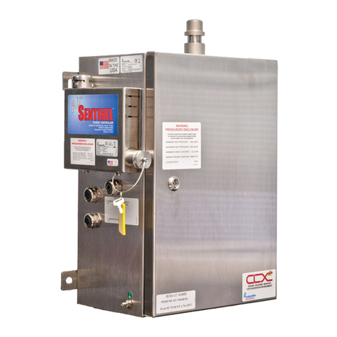
HF Scientific CLX-Ex User manual

PURGE SYSTEM
INSTALLATION MANUAL
CLX-Ex
Model 28031
HF scientific
3170 Metro Parkway
Ft. Myers, FL 33916
Phone: 239-337-2116
Toll Free: 888-203-7248
Fax: 239-332-7643
Website: www.hfscientific.com
Catalog No 28815A
Rev 1.6 (9/11)


DECLARATION OF CONFORMITY
0359 II 2G Ex px IIC T4 Gb
To the following standards:
Explosive Atmospheres –Part 0: Equipment –General Requirements, EN60079-0: 2009
Explosive Atmospheres –Part 2: Equipment Protection by Pressurized Enclosure “p”, EN60079-2: 2007
Emissions & Immunity –Tested and passed EN61326: 1997 + A1: 1998 + A2: 2001 + A3: 2003
Manufacturer’s Name: HF scientific inc.
Manufacturer’s Address: 3170 Metro Parkway, Fort Myers, Florida 33916-7597
Importer’s Name:
Importer’s Address:
Type of Equipment: Chlorine Process Monitor
Model: CLX-Ex
I, the undersigned, hereby declare that the equipment specified above conforms to the above Directive and
Standard
Place: Fort Myers, Florida USA
(Signature)
Date: 1 June 2011 Rowan T. Connelly, General Manager
Catalog No 28815A
Rev 1.6 (9/11)


Table of Contents
Section Page
Specifications....................................................................................................1
1.0 Orientation .......................................................................................................2
2.0 Safety.................................................................................................................3
2.1 Symbols Used In CLX-Ex .....................................................................3
2.2 Use in Explosive Environments Safety..................................................3
3.0 Installation and Commissioning ....................................................................4
3.1 Air Supply ............................................................................................4
3.2 Electrical Connections ..........................................................................4
3.3 System Power ........................................................................................4
4.0 Purge Control X-Purge Controller Operation .............................................5
4.1 Start Up .................................................................................................5
4.2 Indicator Lamp.......................................................................................5
4.3 Maintenance By-Pass Operation............................................................6
5.0 Operation .........................................................................................................6
6.0 Instrument Labels ...........................................................................................7
Catalog No 28815A
Rev 1.6 (9/11)

CLX-Ex (9/11) Page 1
REV 1.6
Specifications
Measurement Range
0.00 –10.00 mg/L (PPM)
Accuracy
±5% of reading or ±0.03 mg/L (PPM) whichever is greater for range of
0-6.0 mg/L(PPM) ±10% of reading from 6.01-10.00 mg/L (PPM)
Resolution
0.01 mg/L (PPM)
Cycle Time
Adjustable; 110 seconds to 10 minutes (600 seconds)
Note: the system defaults to 2.5 minutes
Display
Multi-Line Liquid Crystal Backlit Display
Alarms
Standard: Two Programmable, 120-240VAC 2A Form C Relay
Remote Standby Option: One NO relay contact 120-240VAC 2A
Analog Output
Powered 4-20 mA, 600 drive, isolated
Communications Port
Bi-directional RS-485 with Modbus
Water Pressure
Integral pressure regulator 0.34 bar (5.0 PSI) to 10.3 bar (150 PSI.)
Flow Rate to Waste
200 –400 ml/min.
Operating Temperature
0°C –55°C (32°F –131°F)
Wetted Materials
PVC, Borosilicate Glass, Reslyn (FFKM), Viton®(FKM),
Polypropylene, 316 Stainless Steel, Acetal, Noryl®, Silicone
Sample Temperature Range
0°C –55°C (32°F –131°F)
Power Supply
240 VAC (130 to 240VAC), 47-63 Hz, 250VA
Insulation Rating
Double Insulated, Pollution Degree 2, Overvoltage Category II
Environmental Conditions
Not recommended for outdoor use.
Altitude up to 2000 meters
Up to 95 % RH (non-condensing)
Atex Rating
0359 II 2G Ex px IIC T4 Gb
Compressed Air
Water and oil free, -40oF (-40oC) Dew Point, Particles <5u, ISA Grade
Hydrocarbon Free. Full time clean dry air at 5.5 -7 bar (80-101.5 PSI)
@ 112 SLPM (4 SCFM) @ 20oC (68oF) Max
Regulatory Compliance
And Certifications
CE Approved, ETL listed to UL 61010-12004 &ETL certified to CSA
22.2 No. 61010.1 2nd edition dated July 2004
EN61326:1997 + A1:1998 + A2:2001 + A3:2003
Shipping Weight
28 kg (62lbs.) Reagents are Shipped Separately
Shipping Dimensions
775 mm X 622 mm X 318 mm (30½ ” X 24 ½” X 12 ½”)

CLX-Ex (9/11) Page 2
REV 1.6
VORTEX ASSEMBLY
PURGE
CONTROL
INLET WATER STRAINER
BUFFER REAGENT
BOTTLE
PUMP SOLENOID
OPTICAL BLOCK ASSY
MAIN CONTROL
CHASSIS
TEMPERATURE CONTROL
(UNDER FINGER GUARD)
WIRING COVER
REPLACEMENT
REAGENT CONTAINER
GROUND LUG
WATER REGULATOR
DRAIN AIR INLET & WATER INLET
WATER INLET
AIR INLET
POWER INLET
I/O SIGNALS
VENT ASSEMBLY
1.0 Orientation
From the diagram below the major components can be located.
Figure 3: The CLX-Ex with Cover Open

CLX-Ex (9/11) Page 3
REV 1.6
2.0 Safety
This manual contains basic instructions that must be followed during the commissioning,
operation, care and maintenance of the instrument. The safety protection provided by this
equipment may be impaired if it is commissioned and/or used in a manner not described in
this manual. Consequently, all responsible personnel must read this manual prior to
working with this instrument.
In certain instances “Notes”, or helpful hints, have been highlighted to give further
clarification to the instructions. Refer to the Table of Contents to easily find specific topics
and to learn about unfamiliar terms.
Note: This manual is intended to be used in conjunction with the companion manual Cat. No.
28815B.
2.1 Symbols Used In CLX-Ex
Standard IEC symbols are used on the high voltage cover.
ISO 3864, No. B.3.6 Caution, risk of electric shock.
This symbol indicates that hazardous voltages. This symbol is used in
this manual to bring attention to a potential electrical hazard
ISO 3864, No.B3.1 Caution refer to accompanying documents.
This symbol is reminding you to read the sections in the manual referring
to the electrical connections, and potential hazards.
This symbol is used to bring attention to a special feature or to provide
additional information.
2.2 Use in Explosive Environments Safety
In the interests of safety the operator must ensure the atmosphere where the instrument is
located is safe from gases, vapors, dust or other flammable conditions whenever the
instrument is opened for service or maintenance. At all other times the door must be kept
closed with purge air connected the purge system operating with the GREEN lamp lit
indicating safe operation.

CLX-Ex (9/11) Page 4
REV 1.6
3.0 Installation and Commissioning
3.1 Air Supply
This instrument requires Water and oil free air, -40oC (-40oF) Dew Point, Particles <5u, ISA
Grade Hydrocarbon Free. Fulltime clean dry air at 5.5 - 7 bar (80-101.5 PSI) @ 112 SLPM
(4 SCFM) @ 20oC (68oF) Max. is required. This air supply must be provided continuously
from a known safe area.
The air connection requires 6 mm stainless steel tubing. A compression type fitting is
supplied that simply requires the installer to slip the supplied nut and feral over the tubing
and then tighten the nut.
3.2 Electrical Connections
The power cable enters cabinet through a grommet. The power cable diameter must be
selected to ensure that this connection is tight. The grommet can accept cabling from 9 to 17
mm diameter. This grommet must be tightened to maintain cabinet air pressure.
The electrical power for the protective gas supply (blower, compressor, etc.) should be
either taken from a separate power source or taken from the supply side of the electrical
isolator for the pressurized enclosure.
Only qualified electricians should be allowed to perform the installation of the
instrument as it involves a line voltage that could endanger life.
3.3 System Power
The Purge Control X-Purge controller requires 220-240
VAC 47-63 HZ.
A total power requirement of 250VA; please verify that the
line voltage falls within these specifications. A circuit
breaker must be placed prior to the power connection in
close proximity and within easy reach to allow for service.
This circuit breaker must be marked to indicate that it is a
disconnecting means for the instrument.
Supply power connections are made ONLY to the back of
the Purge Control X-Purge controller:
Terminal 1: Line or Hot connection
Terminal 2: Neutral
Terminal 3: Ground
Suitable wire would be stranded, 3 conductors 18-12 AWG
copper or tin plated copper with a voltage rating of
600VAC with a temperature rating of 90 ˚C or higher.
Common earth bond points are provided both inside the
enclosure on the chassis and outside of the enclosure.

CLX-Ex (9/11) Page 5
REV 1.6
The instrument is prewired using a DIN rail mounted terminal strip. This is for
internal connections only. NO USER CONNECTIONS SHOULD BE MADE TO THIS
CONNECTION STRIP.
4.0 Purge Control X-Purge Controller Operation
The Purge Control X-Purge controller is mounted on the side of the main enclosure. This
controller will ensure proper safe operation of the CLX-Ex. If of all the required conditions
are met, the controller will act as a power governor. It does this by monitoring the
pressurization of the main enclosure with clean dry air. Should this air supply pressure fail
the indicator lamp on the Purge Control X-Purge unit will turn RED and power to the rest of
the instrument is disconnected.
WARNING: Do not apply power to the Purge Control X-Purge controller unless the
area has been properly tested and is known not to contain explosive materials.
4.1 Start Up
When power is applied to the CLX-Ex for the first time, ensure that the air supply is
connected as stated in section 4.1 and the cabinet is closed and locked. Once power is
applied, the Purge Control X-Purge will go through a purge period of 5 minutes where at
least five volumes of the enclosure are pushed through the CLX-Ex and out the vent at the
top of the instrument. During the purge period the indicator lamp mounted on top of the
Purge Control X-Purge will flash GREEN indicating the purge is in process and no power is
applied to the rest of the CLX-Ex.
At the complete of the purge, indicator lamp will go solid GREEN and power will be
applied to the rest of the system. As long as the proper air supply conditions are met the
CLX-Ex will continue to operate.
4.2 Indicator Lamp
The indicator lamp is a very quick way to determine to operation of the controller and thus
the safety condition of the CLX-Ex.
Lamp Color
Meaning
Power to rest of CLX-Ex
Solid GREEN
Safe Operation
Power ON
Flashing Green
Instrument purging
Power OFF
Solid RED
Unsafe Operation
Power OFF
Flashing Red
By-Pass Key Operating
Power ON
NO Lamp
No power applied to CLX-Ex
No power applied everything off.
Using the table above, you can quickly determine the operating condition of the instrument.
Under normal operation a solid GREEN lamp should appear.

CLX-Ex (9/11) Page 6
REV 1.6
4.3 Maintenance By-Pass Operation
WARNING: Use of the by-pass key disables the safety features and safe operation of
this instrument. It is imperative that this operation be performed only after the area
has been tested and known to be safe.
To perform some maintenance operations on the CLX-Ex it is necessary to have the entire
instrument powered up while the enclosure door is open. Under these conditions normally
the Purge Control X-Purge controller would determine that the enclosure is not pressurized
and power will be removed to the measurement section of the CLX-Ex. To allow for this
situation, a special maintenance by-pass key is supplied.
Located on the right side of the Purge Control X-Purge controller is a hex cap. Removing
this cap reveals the key slot. Insert the key and turn it clockwise to engage the bypass
operation. The indicator lamp will flash Red to indicate the by-pass mode. Assuming the
area around the CLX-Ex has been tested and known to be safe, the enclosure door can now
be safely opened and power will remain on to the entire system. The key cannot be removed
while operating in the maintenance by-pass mode.
WARNING: Do not operate the CLX-Ex for long periods of time in the by-pass mode.
This is intended only for maintenance operations.
WARNING: Do not operate the CLX-Ex in the by-pass mode unattended.
To return the instrument to normal, safe operation, close the enclosure door. Ensure that the
air supply is connected turn the key counter-clockwise and remove. Replace the hex cover.
If the pressure in the cabinet has built up to a normal acceptable level the lamp will show
solid GREEN and the system will continue to run.
5.0 Operation
Under normal operation the Purge Control X-Purge controller lamp will a solid GREEN
indicating safe operation. If the lamp is not solid GREEN, correct this condition first.
Please refer to section 5.0 Purge Control X-Purge Controller Operation.
All connections that carry power not generated inside the CLX-Ex, with the exception
of the mains, must be connected through Intrinsic Safety Barriers.
Please note that these operating screens cannot be seen except with the cabinet door
open and the instrument in maintenance by-pass mode. See section 5.3 for more
information on this.

CLX-Ex (9/11) Page 7
REV 1.6
6.0 Instrument Labels
The following labels can be found on the outside of the CLX-Ex.
Purpose
Location
Label
Electrical
Grommet
Purpose
Enclosure Left
Side
Water and Air
Connections
Enclosure Lower
Panel
Model Name,
Manufacturer
Enclosure front
door
Warning
Enclosure Front
door

CLX-Ex (9/11) Page 8
REV 1.6
Warning
Enclosure Front
Door
Warning
Enclosure Front
Door
Warning
Reagent Kit
WARNING
THE REAGENT KIT ENCLOSURE IS NOT
TO BE OPENED OR RESEALED UNLESS
THE ATMOSPHERE IS KNOWN TO BE
FREE FROM EXPLOSIVE GASSES
Information
Front Cover
Other manuals for CLX-Ex
1
This manual suits for next models
1
Table of contents
Other HF Scientific Measuring Instrument manuals
