HGM SZI User manual

Valve box “SZI”
for compressed medical gases and the vacuum
complying to EN ISO 7396-1
INSTRUCTION MANUAL

2
Table of contents
1. Technical data ................................................................................................................................. 3
1.1 Information about the device ...................................................................................................... 3
2. Application ...................................................................................................................................... 3
3. Construction ................................................................................................................................... 4
4. Installation ...................................................................................................................................... 4
5. Operation ........................................................................................................................................ 4
5.1 First start-up ............................................................................................................................... 4
6. Maintenance / repair ...................................................................................................................... 5
6.1 List of spare parts ....................................................................................................................... 5
6.2 List of the authorized service points .......................................................................................... 5
8. Alarm system .................................................................................................................................. 7
8.1 Alarm unit mounted in valve box ............................................................................................... 7
8.2 Description of connections in alarm unit ................................................................................... 8
9. Remote alarm unit .......................................................................................................................... 8
9.1 Under plaster version ................................................................................................................. 8
9.1.1 Assembly drawing of under plaster alarm unit ................................................................... 9
9.2 Remote alarm unit – on wall version ......................................................................................... 9
9.2.1 Display .............................................................................................................................. 10
9.2.2 Mounting of on plaster alarm unit ..................................................................................... 10
9.3 Connecting cables .................................................................................................................... 11
9.4 Exemplary diagram of the central monitoring system ............................................................. 12

3
1. Technical data
Construction: flush-mounted part is made of plastics or steel sheet, wall-mounted part (doors)
white, powder coated, equipped with the lock with the emergency
unlocking, inlet and outlet of gas from the top.
Pressure: compressed gases 0 – 10 bar
vacuum 0 - -0.9 bar
Weight Outer dimensions (WxHxD)
SZI-1 4.5 kg 380x450x90
SZI-2 6.1 kg 380x450x90
SZI-3 7.3 kg 380x450x90
SZI-4 10.5 kg 560x480x90
SZI-5 14.2 kg 560x480x90
SZI-6 15.4 kg 560x480x90
Power supply: 12V DC, 0.1A
Assembly: Flush-mounted or wall-mounted in a housing
Pressured inlets/outlets from the top: copper pipe 15x1.
Vacuum inlets/outlets from the top: copper pipe 15,18,22x1 or according to the design.
Optionally only informative inlets.
The box is equipped with a system of analog pressure converters 0-5V and built-in gas monitor. Too
high or too low level or excessive gas consumption is signaled optically and acoustically (break-down
consisting in damage of the distribution conduits or the medical equipment).
1.1 Information about the device
Device should be stored in a dry place in temperature between +10 C - +45 C.
The valve box is a part of a central gas supply system according to EN ISO 7396-1. The pipes
in the pipeline must by hard soldered.
The valve-informative box, according to 93/42/EWG directive and the decree of the Minis-
try of Health, Journal of Laws No 16 item 74 dated January 12, 2011 is a medical manufac-
tured product – class IIb.
2. Application
For monitoring pressure of medical gases and vacuum for hospital units, operating theatres, ICU
rooms in central gas supply systems. Possibility of transmitting information to the central alarm unit
or central computer.

4
3. Construction
The housing of the valve box contains up to 6 shut-off valves, analog pressure converters 0-5V,
emergency supply point type NIST and gas alarm unit with LCD display mounted on the doors.
4. Installation
Wall mounting of the housing – the doors should be disassembled prior to the assembly.
Connection of copper pipes to the main system.
Before start-up of the installation the doors should be assembled again.
Supply the 12V DC voltage to a box.
Connect „+” and „-” poles to marked pins.
!!! Attention !!!
Mounting must be performed ONLY by qualified technicians experienced in servicing
medical equipment.
Read manual before mounting valve box.
!!! Attention !!!
Polarity of the connection is very important, any mistake causes a damage of the electronic
system
!!! Attention !!!
Before performing a leak test vacoumeter should be removed.
Perform leak test of pipeline system in accordance with the EN ISO 7396-1;
5. Operation
5.1 First start-up
1. Before start-up make sure all tests in accordance with EN ISO 7396-1 finished successfully.
2. Slowly open each valves in box;
3. Make sure that pressures in manometers are as determined by project;
4. Connect power supply;
5. Make sure that alarm unit shows correct informations (gas type and pressure);
6. Device is ready to use.
In order to use shut-off valves, the doors must be opened.
The box may also be opened without a key in case of an emergency. This is done by pushing the lock
with the plastic mounting into the box. Upon completion of the necessary steps, the plastic mounting
fixing the lock should be replaced and put back in the door. Close the door with a key.

5
According to EN ISO 7396-1, the valve box is equipped with the physical unsealing. For this purpose
the relevant shut-off valve must be closed, the pipeline behind the valve should be emptied. Then,
physical cut-off may be unscrewed and screwed in again after the works.
For the emergency supply, NIST connectors should be used. They are encoded for the given
gas. NIST connectors together with the pressure reducer should be mounted on the emergency bottle
with compressed gas, placed in proper socket, pushing it in and screwing down the pin cap. Before
opening of the valve of the bottle, it is required to loosen reducer’s hand wheel. After slow opening
of the valve of the bottle the pressure on the reducer may be set as per working pressure in the instal-
lation.
6. Maintenance / repair
Each valve box must be subjected to maintenance at least once a year. In particular, it is re-
quired to check the shut-off valves and points of emergency supply and check the tightness of the
pressure connections inside the box. Any repairs may only be performed by a qualified personnel.
Use only genuine parts of HYDRO-GAZ-MED Sp.j.
6.1 List of spare parts
Analog pressure transducer 0-16 bar –
Cat. No.: 3100R0016G05B000
Analog pressure transducer -1-0 bar –
- Cat. No.: 3300R00B0V05B00001
ball valve ½” degreased – cat. No.: ZKUL-DN15
Signaling device with measuring module – cat. No.: IBPL H0122N
Remote signaling device – cat. No.: IBPL-H01
6.2 List of the authorized service points
Hydro-Gaz-Med. Sp.j.,
Willowa 40 St.,
05-205 Dobczyn,
Poland
tel. +48 22 787 65 60,
6
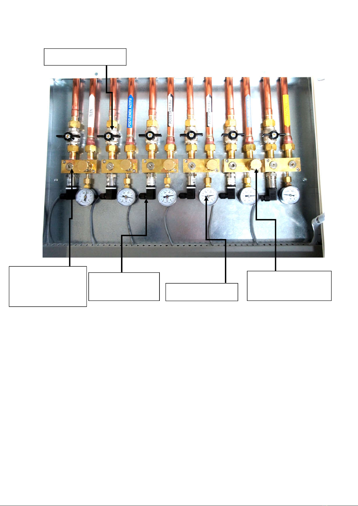
7. Cosntruction diagram
emergency supply
point NIST
Phisical opening
of pipeline
system
Pressure
transducer Manometer
Shut off valves

7
8. Alarm system
8.1 Alarm unit mounted in valve box
Functions: transmission of data to the remote alarm unit and display of information on the status of
the monitored gases together with visual and audio alarm status.
Power input: < 750mW
Length: 148 mm
Width: 80 mm
Height: 41 mm
Weight: ca 165 g
Screen overview
For each gas its pressure is displayed with the accuracy of a tenth of a bar. In case the pressure of any
of the gases is lower than this user-defined in the program, the name of the gas and red diode start to
blink, and the sonic alarm activates. The sonic alarm may be switched off for a period of 15 minutes
by pressing a button. If the pressure of a gas is higher than the user-defined in the system, the name
of the gas and green diode start to blink, and the sonic alarm activates. The sonic alarm may be
switched off for a period of 15 minutes by pressing a button.

8
8.2 Description of connections in alarm unit
9. Remote alarm unit
9.1 Under plaster version
Functions: displays informations on a status of monitored gasses together with visual and audio
signalling the alarm status. The remote alarm unit operates identically as the alarm unit
mounted in the valve box.
Power input: < 100 mA
Length: 180 mm
Width: 90 mm
Height: 42 mm
Weight: ~ 200 g
Blocks for connecting
analog converters
12V DC connection block
+12V
-

9
9.1.1 Assembly drawing of under plaster alarm unit
9.2 Remote alarm unit – on wall version
Alarm unit is equipped in touchscreen. On the screen there is TEST buton, which should be
weekly used to check functioning of alarm unit.
On the housing we have dual color LED from visual signal. In case of alarm the LED blinks;
green light when pressure is to high, and red light when pressure is to low.
With each visual signal there is also audio signal.
10
-OK- 1/001 bar
O2 5.1 VAC -0.6
N2O 4.9
AIR5 4.8
Sygnalizator gazów
medycznych
To mute the audio signal we need to touch the bell symbol on the screen. After 15 minutes, if
the cause of the alarm was not removed, audio signal returns. It will be returning till cause of the
alarm will not be gone.
During normal work green is LED is constantly ON.
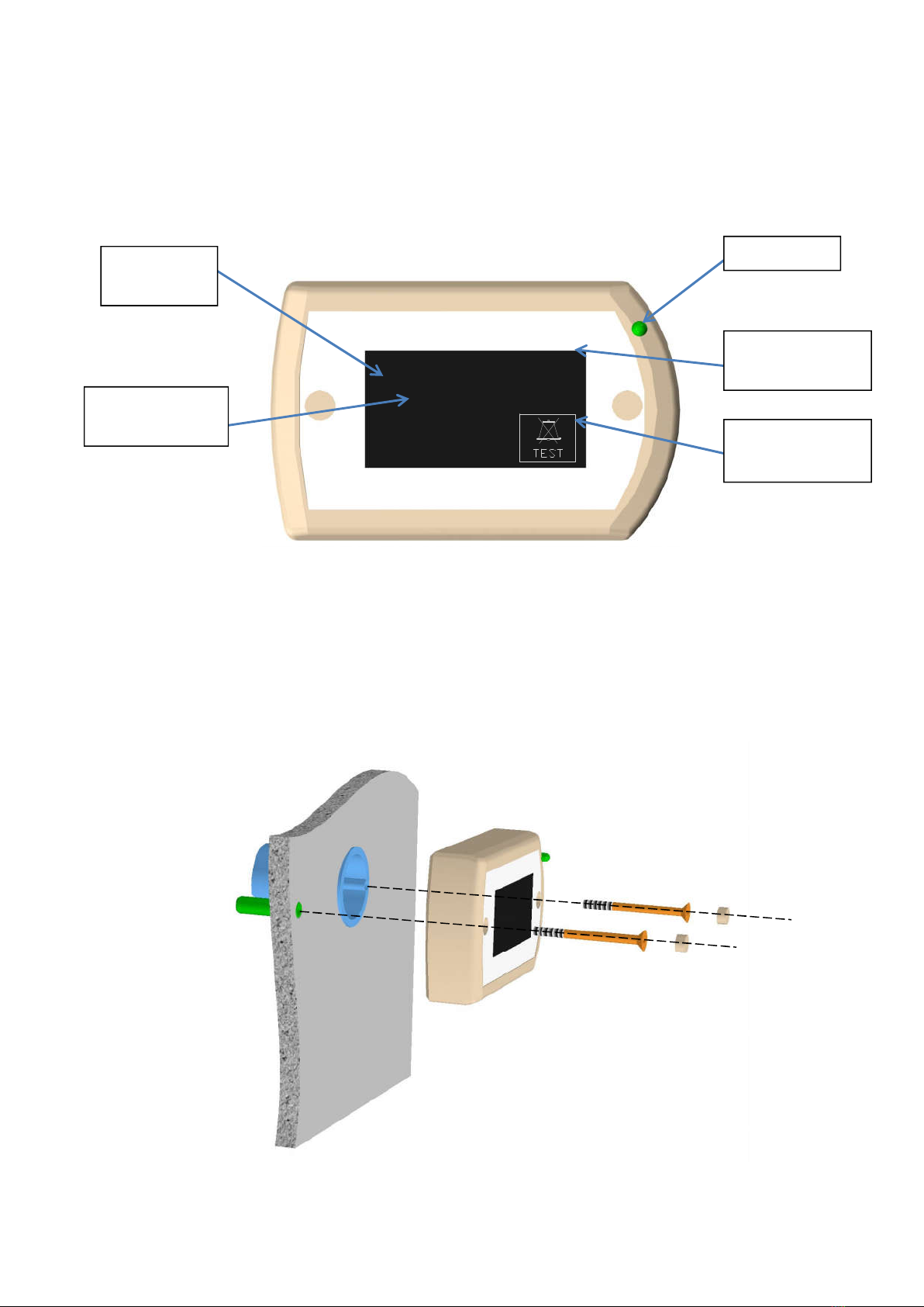
9.2.1 Display
9.2.2 Mounting of on plaster alarm unit
Scope of delivery:
- 35 mm plastic under plaster casing
- 2 screws and 1 fisher
- plugs for installation holes
gas
symbol
pressure
value
LED
pressure
unit
TEST / mute
button
Table of contents
Popular Control Unit manuals by other brands

Festo
Festo Compact Performance CP-FB6-E Brief description

Elo TouchSystems
Elo TouchSystems DMS-SA19P-EXTME Quick installation guide

JS Automation
JS Automation MPC3034A user manual

JAUDT
JAUDT SW GII 6406 Series Translation of the original operating instructions

Spektrum
Spektrum Air Module System manual

BOC Edwards
BOC Edwards Q Series instruction manual

KHADAS
KHADAS BT Magic quick start

Etherma
Etherma eNEXHO-IL Assembly and operating instructions

PMFoundations
PMFoundations Attenuverter Assembly guide

GEA
GEA VARIVENT Operating instruction

Walther Systemtechnik
Walther Systemtechnik VMS-05 Assembly instructions

Altronix
Altronix LINQ8PD Installation and programming manual


