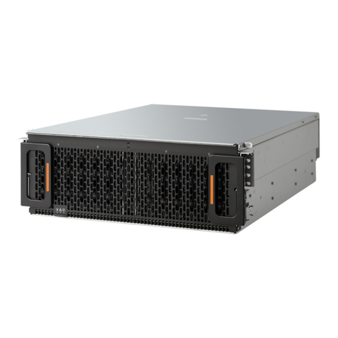
HGST Ultrastar Serv24-HA User manual

Contents
Revision History..............................................................................................7
Points of Contact.............................................................................................8
Copyright........................................................................................................9
Supported SKUs...........................................................................................10
Chapter 1 Ultrastar Serv24-HA Overview...............................................11
1.1 Ultrastar®Serv24-HA Description....................................................11
1.2 Block Diagrams................................................................................12
1.3 Ultrastar Serv24-HA Specification Summary...................................14
1.4 System Architecture Overview.........................................................16
1.5 Ultrastar Serv24-HA Layout.............................................................16
1.6 Ultrastar Serv24-HA Rack Requirements........................................16
1.7 List of Replaceable Components.....................................................17
1.8 LEDs................................................................................................18
1.8.1 Chassis LEDs...............................................................................18
1.8.2 PSU LED......................................................................................19
1.8.3 Drive LEDs...................................................................................19
1.9 Input/Output.....................................................................................20
1.9.1 Rear I/O Ports and Features........................................................20
1.10 List of Compatible Drives...............................................................20
Chapter 2 Component Overviews...........................................................22
2.1 Chassis Description.........................................................................22
2.1.1 Chassis Specifications.................................................................22
2.1.2 Chassis Layout.............................................................................23
2.2 PIB Canister Description..................................................................23
2.2.1 PIB Canister Specifications..........................................................24
2.2.2 PIB Canister Layout......................................................................24
ii
Contents
User Guide

2.3 PSU Description...............................................................................25
2.3.1 PSU Specifications.......................................................................25
2.3.2 PSU Layout..................................................................................26
2.4 Drive Description..............................................................................27
2.4.1 Drive Specifications......................................................................27
2.4.2 Drive Layout.................................................................................28
2.5 Drive Blank Assembly Description...................................................29
2.5.1 Drive Blank Assembly Specifications...........................................29
2.5.2 Drive Blank Assembly Layout.......................................................30
2.6 Fan Description................................................................................31
2.6.1 Fan Specification..........................................................................31
2.6.2 Fan Layout....................................................................................32
2.7 Compute Canister Description.........................................................32
2.7.1 Compute Canister Specification...................................................33
2.7.2 Compute Canister Layout.............................................................33
2.8 Rails Description..............................................................................34
2.8.1 Rails Specification........................................................................34
2.8.2 Rails Layout..................................................................................34
2.9 Battery Backup.................................................................................35
2.9.1 Battery Backup Specification.......................................................35
Chapter 3 Part Replacement...................................................................36
3.1 Drive Assembly Replacement..........................................................36
3.2 Drive Blank Assembly Replacement................................................37
3.3 DIMM Replacement.........................................................................39
3.4 CPU and Heat Sink Module Replacement.......................................43
3.5 Heat Sink Replacement...................................................................51
3.6 M.2 Boot Drive Replacement...........................................................61
3.7 NIC Replacement.............................................................................66
3.8 PSU Replacement............................................................................72
3.9 PIB Canister Replacement...............................................................74
iii
Contents
User Guide

3.10 Rails Replacement.........................................................................78
3.11 Chassis Replacement....................................................................88
3.12 Compute Canister Replacement..................................................105
3.13 (Optional) Battery Backup Replacement......................................117
Chapter 4 System Management............................................................124
4.1 Managing Ultrastar Serv24-HA......................................................124
4.2 Downloading Firmware from the Support Portal............................124
4.3 Web UI Overview...........................................................................127
4.3.1 Web UI Supported Browsers......................................................129
4.3.2 Creating a New User in Web UI.................................................129
4.3.3 Changing Network Settings in Web UI.......................................133
4.3.4 Changing the DNS Configurations in Web UI............................134
4.3.5 Updating BIOS Firmware in Web UI...........................................135
4.3.6 Updating BMC Firmware in Web UI...........................................137
4.3.7 Checking the Status of the Enclosure Sensors in Web UI.........140
4.3.8 Viewing System Inventory using Web UI....................................141
4.3.9 Viewing System Logs and Reports in Web UI............................144
4.3.10 Identifying the Enclosure using Web UI...................................148
4.3.11 Power Off/Reset the Enclosure using Web UI..........................149
4.4 IPMI Overview................................................................................151
4.4.1 Accessing IPMI on Linux............................................................151
4.4.1.1 Creating a New User Using IPMItool......................................151
4.4.1.2 Configuring Network Settings Using IPMItool........................153
4.4.1.3 Checking Compute Canister Sensors using IPMItool.............153
4.4.1.4 Viewing System Logs and Reports using IPMItool.................155
4.4.1.5 Power Off/Reset the Compute Canister using IPMItool.........156
4.5 CFUFlash Overview.......................................................................156
4.5.1 Accessing CFUFlash..................................................................156
4.5.2 Updating BIOS Firmware using CFUFlash.................................157
4.5.3 Updating BMC Firmware using CFUFlash.................................158
iv
Contents
User Guide

Chapter 5 Disclaimers............................................................................159
5.1 Safety Compliance.........................................................................159
5.2 Restricted Access Location............................................................159
5.3 Regulatory Statement....................................................................159
5.4 Electromagnetic Compatibility (EMC) Class A Compliance ..........160
5.5 Country Certifications....................................................................160
Chapter 6 Safety.....................................................................................162
6.1 Electrostatic Discharge..................................................................162
6.2 Optimizing Location........................................................................162
6.3 Power Connections........................................................................162
6.4 Power Cords...................................................................................163
6.5 Replaceable Batteries....................................................................163
6.6 Rackmountable Systems...............................................................163
6.7 Safety and Service.........................................................................164
6.8 Safety Warnings and Cautions.......................................................164
Chapter 7 Regulatory Statements.........................................................165
7.1 Europe (CE Declaration of Conformity)..........................................165
7.2 FCC Class A Notice.......................................................................165
7.3 ICES-003 Class A Notice—Avis NMB-003, Classe A....................165
7.4 Japanese Compliance Statement, Class A ITE.............................165
7.5 Taiwan Warning Label and RoHS Statement, Class A ITE............166
Appendix A System Management Appendices........................................168
A.1 IPMItool Commands......................................................................168
A.2 IPMItool LAN Key Options.............................................................168
A.3 IPMItool User Commands..............................................................169
A.4 Standard IPMI Command Support List..........................................170
v
Contents
User Guide

A.5 CFUFlash Commands...................................................................174
A.6 CFUFlash Options.........................................................................174
A.7 CFUFlash Medium.........................................................................175
Appendix B System Operations Appendices............................................176
B.1 ESD...............................................................................................176
B.2 System Cooling..............................................................................176
B.3 Power Requirements.....................................................................176
B.4 Host Connectivity...........................................................................177
Appendix C Compatibility.........................................................................178
C.1 Compatible Operating Systems List..............................................178
C.2 Compatible Parts List.....................................................................178
vi
Contents
User Guide

Revision History
CommentRevisionDate
Initial ReleaseRevision 1.0February 2018
Added the Battery Backup on page 35 section to the Component
Overviews on page 22
Revision 1.1April 2018
Updated the following:
•List of Replaceable Components on page 17
Revision 1.2August 2018
•Part Replacement on page 36
•CFUFlash Overview on page 156
•Taiwan Warning Label and RoHS Statement, Class A ITE on
page 166
7
Revision History
User Guide

Points of Contact
For further assistance with an HGST product, contact Global Service and Support. Please be prepared to
provide the following information: Serial Number (S/N), product name, model number, and a brief description
of the issue.
Email:
Website:
http://support.hgst.com
8
Points of Contact
User Guide

Copyright
The following paragraph does not apply to the United Kingdom or any country where such provisions
are inconsistent with local law: HGST a Western Digital company PROVIDES THIS PUBLICATION "AS
IS" WITHOUT WARRANTY OF ANY KIND, EITHER EXPRESS OR IMPLIED, INCLUDING, BUT NOT
LIMITED TO, THE IMPLIED WARRANTIES OF MERCHANTABILITY OR FITNESS FOR A PARTICULAR
PURPOSE. Some states do not allow disclaimer or express or implied warranties in certain transactions,
therefore, this statement may not apply to you.
This publication could include technical inaccuracies or typographical errors. Changes are periodically made
to the information herein; these changes will be incorporated in new editions of the publication. HGST may
make improvements or changes in any products or programs described in this publication at any time.
It is possible that this publication may contain reference to, or information about, HGST products (machines
andprograms),programming, or services that are not announced in yourcountry.Suchreferences or information
must not be construed to mean that HGST intends to announce such HGST products, programming, or
services in your country.
Technical information about this product is available by contacting your local HGST representative or on the
Internet at: support.hgst.com
HGST may have patents or pending patent applications covering subject matter in this document. The furnishing
of this document does not give you any license to these patents.
Copyright ©2017-2018 Western Digital Corporation or its affiliates.
Western Digital
5601 Great Oaks Parkway
San Jose, CA 95119
Long Live Data™is a trademark of HGST, Inc. and its affiliates in the United States and/or other countries.
HGST trademarks are authorized for use in countries and jurisdictions in which HGST has the right to use,
market and advertise the brands.
Other product names are trademarks or registered trademarks of their respective owners.
One MB is equal to one million bytes, one GB is equal to one billion bytes, one TB equals 1,000GB (one trillion
bytes) and one PB equals 1,000TB when referring to storage capacity. Usable capacity will vary from the raw
capacity due to object storage methodologies and other factors.
References in this publication to HGST products, programs or services do not imply that HGST intends to
make these available in all countries in which HGST operates.
Product information is provided for information purposes only and does not constitute a warranty.
Information is true as of the date of publication and is subject to change. Actual results may vary. This publication
is for general guidance only. Photographs may show design models.
9
Copyright
User Guide

Supported SKUs
The following table lists the versions of this HGST product that are supported by this document.
SKUs
1ES10381ES10301ES10371ES1029
1ES10011ES10311ES10391ES1000
1ES10411ES10031ES10401ES1032
1ES10431ES10331ES10421ES0405
1ES10451ES10351ES10441ES1034
1ES10021ES10361ES10461ES0404
10
Supported SKUs
User Guide

Chapter
1
1 Ultrastar Serv24-HA Overview
1.1 Ultrastar®Serv24-HA Description
Figure 1: Ultrastar Serv24-HA
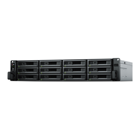
The Ultrastar®Serv24-HA is a high availability 2U, 24 bay, dual node storage server. The maximum data
storage capacity of the Ultrastar Serv24-HA is 184.32 TB using HGST Ultrastar®SN200 drives. For a full list
of compatible drives and total storage capacities, see the List of Compatible Drives on page 20. The
enclosure runs on an input voltage of 200-240VAC and consumes ~1800W under typical conditions. It is
designed to fit within a 2U rack space and requires a minimum of See EIA-310 Rack Standard.
• 2U Storage Server
• 24 NVMe drives
• Redundant 1800W PSUs
• Two hot-swappable Compute Canisters (each list item represents the content of one Compute Canister)
• Contains a Intel Purely platform motherboard
• Dual Skylake processor design with Lewisburg PCH
• Supports up to 12 DIMMs per CPU, 24 per Compute Canister
• Five fan modules
• Aspeed AST2500 Board Management Controller (BMC)
• Three PCIe generation 3 slots (one slot open for user expansion)
• Two M.2 boot drives
• Two dual-port 100 GbE NIC cards
• One VGA port
• Two USB 3.0 ports
• Four 10 GbE ports (per Compute Canister)
• One 1 GbE port for system management that can be controlled through IPMI or Web UI
• (optional) TPM Module
• (optional) Battery Back-up Module
11
1 Ultrastar Serv24-HA Overview
User Guide 1.1 Ultrastar®Serv24-HA Description

1.2 Block Diagrams
Figure 2: Enclosure System Block Diagram
Figure 3: NVMe Canister Block Diagram
12
1 Ultrastar Serv24-HA Overview
User Guide 1.2 Block Diagrams

Figure 4: Processor Block Diagram
13
1 Ultrastar Serv24-HA Overview
User Guide 1.2 Block Diagrams

Figure 5: PCIe Switch (PM8546) Block Diagram
1.3 Ultrastar Serv24-HA Specification Summary
Table 1: Environmental Specification Summary
OperationalNon-OperationalSpecification
5°C to 35°C-40°C to 60°CTemperature
20°C per hour max30°C per hour maxTemperature Gradient
14
1 Ultrastar Serv24-HA Overview
User Guide 1.3 Ultrastar Serv24-HA Specification Summary

OperationalNon-OperationalSpecification
1°C per 300m above 950m1°C per 300m above 12000mTemperature De-rating
8-85% Non-Condensing8-95% Non-CondensingRelative Humidity
30% per hour maximum30% per hour maximumRelative Humidity Gradient
950m to 3048m950m to 12000mAltitude
Table 2: Electrical Specifications
ValueSpecification
~1980W (for one second)Max Power Consumption
~1800WTypical Power Consumption
200-240VACInput Voltage
C14PSU Connector Type
AC line inrush current shall not exceed 30A peak,
for up to one-quarter of the AC cycle, after which,
Inrush Current Maximum (per PSU)
the input current should be no more than the
specified maximum input current.
80 Plus™PlatinumPSU Efficiency
Table 3: Mechanical Specifications
OperationalNon-OperationalSpecification
10G - 5 ms duration; 5 shocks
positive and 5 negative in each of
3 axes, 30 total shocks.
35G - 136 in/sec trapezoid waveShock
0.278G - Random 5-500 Hz 30
minutes per axis, 3 axes (X, Y, Z)
1.04G - 2~200Hz, 15
minutes/faces, six product faces
Vibration
43 kg / 94.8 lbsWeight
48.4 kg / 106.8 lbsWeight w/ Rails
W: 446.4 mm x L:825mmxH: 87.6 mm / W: 17.58in. x L: 32.5in. x
H: 3.4in.
Dimension
482.6 mm / 19 in.Required Rack Width
See EIA-310 Rack StandardRequired Rack Depth
2URack Units (U)
Table 4: Data Capacity Specifications
ValueSpecification
24Number of Drive Slots
184.32 TBMax Raw Data Storage Capacity
15
1 Ultrastar Serv24-HA Overview
User Guide 1.3 Ultrastar Serv24-HA Specification Summary

1.4 System Architecture Overview
TheUltrastarServ24-HA consists of a main chassis that is populated with up to24NVMedrives,twoCompute
Canisters, and redundant 1800W PSUs. Each Compute Canister contains physical connections for dual CPUs,
a platform controller hub (PCH), 24 DIMM sockets, three PCIe generation 3 slots (one slot open for user
expansion), a system BMC, and a removable Trusted Platform Module (TPM). The Ultrastar Serv24-HA
contains four Skylake CPUs (two per Compute Canister) that manage and direct the instructions to the
necessary component in the enclosure. The CPUs supports 1.0 MB Mid-Level Cache (MLC) and Intel
Hyper-Threading Technology per core. The Ultrastar Serv24-HA uses a Lewisburg PCH combined with the
Skylake Server to provide more bandwidth and flexibility in the I/O. It allows for better management of power
within the enclosure and the enclosure components.
The out-of-band management is controlled through Integrated Remote Management Processor system BMC.
Each Compute Canister provides a VGA port, two USB 3.0 ports, 10 GbE ports, and a 1 GbE port using IPMI
and Web UI for BMC management of the enclosure services. The Trusted Platform Module (TPM) provides
system security that communicates with the rest of the system through a device attached to the motherboard.
The TPM is a physical security barrier with a pre-operating system environment that allows for more control
over the software’s security protocol.
1.5 Ultrastar Serv24-HA Layout
Figure 6: Ultrastar Serv24-HA Layout
1
34
4
3
2
Table 5: Ultrastar Serv24-HA Layout
ComponentNumber
Rails1
Drive Bay2
PSU Bay3
Compute Canister4
1.6 Ultrastar Serv24-HA Rack Requirements
TheUltrastarServ24-HA is designed to be installed into a rackthatmeetsthe EIA-310 standard at a minimum.
SeeEIA-310 Rack Standardofusablespace measured fromfrontrack frame to the rear rackframe.It requires
16
1 Ultrastar Serv24-HA Overview
User Guide 1.4 System Architecture Overview

2U of rackspace, and it should be installed into the rack at the lowest possible U height to keep the load on
the rack balanced.
1.7 List of Replaceable Components
Table 6: List of Replaceable Components
HGST Part NumberComponent
1EX1047L6 Enclosure
• Chassis
• Redundant Compute Canisters
• Redundant PSUs (1800W)
• PIB Canisters
• Rails
• Full set of fan modules
1EX1027AC Power Cord (2.5m)
1EX1134Drive Blank
1EX1042PSU (1800W)
1EX1055Battery Backup
1EX1048Rails
1EX1049Compute Canister
1EX1054PIB Canister
1EX1046Fan module
1EX1026SanDisk®X400 SSD M.2 2280 Boot Drive (256GB)
1EX1679Heat Sink
1EX1151Intel®Xeon CPU, 5118 w/ heat sink
1EX1150Intel®Xeon CPU, 6140 w/ heat sink
1EX1045Mellanox®NIC, CX5, 2x100GbE
1EX1044Samsung®DIMM (16GB DDR4)
17
1 Ultrastar Serv24-HA Overview
User Guide 1.7 List of Replaceable Components

1.8 LEDs
1.8.1 Chassis LEDs
Figure 7: Chassis LEDs
1
2
3
Table 7: Chassis LEDs
ActionLEDNumber
• Off: Power off
• Green: Power on
Power1
• Off: Chassis is not being identified
• Blue: Chassis is being identified
Identify2
• Off: No faults reported
• Amber (1Hz Blinking): Warning error
• Amber (4Hz Blinking): Critical error
Fault3
18
1 Ultrastar Serv24-HA Overview
User Guide 1.8 LEDs

1.8.2 PSU LED
Figure 8: PSU LED
1
Table 8: PSU LED
ActionLEDNumber
• Off: PSU not powered on
• Green: Powered on, DC output OK
Fault1
• Amber: Fault, failure, or AC
disconnection on PSU
1.8.3 Drive LEDs
Figure 9: Drive LEDs (Top View)
1
2
Table 9: Drive LEDs
ActionLEDNumber
• Off: No drive present
• Green: Drive present
• Green (Blinking): Drive active
Drive Link/Active1
• Amber: Drive fault reported
• Amber (Blinking): Drive OK
Drive Fault LED2
19
1 Ultrastar Serv24-HA Overview
User Guide 1.8 LEDs

1.9 Input/Output
1.9.1 Rear I/O Ports and Features
Figure 10: Rear I/O Ports and Features
1231
456789
Table 10: Rear I/O Ports and Features
PortNumber
PSU (x2)1
USB 3.02
USB 3.03
1 GbE for IPMI (RJ45)4
10 GbE (RJ45)5
VGA Port (DB-15)6
100 GbE (QSFP28)7
10 GbE (RJ45)8
Serial UART Port9
1.10 List of Compatible Drives
Table 11: Compatible Drives
Part NumberCapacityDrive
1EX10391.92 TBHGST Ultrastar®SN200
RI-1DW/D SE
20
1 Ultrastar Serv24-HA Overview
User Guide 1.9 Input/Output
Table of contents
Other HGST Server manuals

