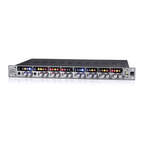
HH Electronics MZ Series User manual

f
ZONE AMPLIFIERS
USER MANUAL
MZ-140D MZ-280Q
MZ-140Q MZ-64P

Page 1
CONTENTS
MZ-SERIES OVERVIEW ...................................................................................................................................... 2
FEATURES ......................................................................................................................................................2
WHAT’S INCLUDED ...................................................................................................................................... 2
CONTROLS.................................................................................................................................................... 3
INSTALLATION GUIDE ...................................................................................................................................... 7
PRIOR CHECKS.............................................................................................................................................. 7
POWER ...........................................................................................................................................................8
MOUNTING ...................................................................................................................................................9
COOLING....................................................................................................................................................... 9
WIRING.........................................................................................................................................................10
INPUTS..........................................................................................................................................................11
OUTPUTS .....................................................................................................................................................15
WALL CONTROLLER WIRING....................................................................................................................20
EXAMPLE CONNECTIONS ........................................................................................................................21
OPERATION......................................................................................................................................................24
TEST STARTUP.............................................................................................................................................24
LIMITERS.......................................................................................................................................................25
FRONT PANEL LOCK..................................................................................................................................25
TROUBLESHOOTING ......................................................................................................................................26
SPECIFICATIONS .............................................................................................................................................27
BLOCK DIAGRAM (64P) .............................................................................................................................28
BLOCK DIAGRAM (280Q) ..........................................................................................................................29
DIMENSIONS...............................................................................................................................................30
SAFETY AND WARNINGS...............................................................................................................................32

Page 2
MZ-SERIES OVERVIEW
The MZ Series from HH is a range of high-performance commercial install amplifiers and pre-
amplifiers. Providing industry leading audio performance and ultra high power in a compact 1U
enclosure. Remote control options are available using a standard CAT5 cable allowing easy
installation.
Suitable for a wide variety of applications such as Retail, Restaurants, Conferences, Bars, Houses of
Worship and Fitness Centres, or indeed anywhere high quality, multi-zone amplification is required.
FEATURES
•Two or four ZONE install amplifiers.
•Four ZONE line level pre-amplifier.
•Class leading audio performance.
•Ultra reliable, high quality PASCAL amp modules.
•EUROBLOCK input and output connectors, Dual balanced XLR MIC/LINE inputs.
•Independent BASS and TREBLE shelving EQ adjustment on each ZONE.
•Compact 1U design (19” rack mountable).
•Universal 100-240V~ worldwide operation.
•Remote volume control capability via RJ45.
WHAT’S INCLUDED
As well as your MZ device, the box will also contain:
•2x 1U rack mounting wings.
•6x CSK M4 10mm machine screws for rack wings.
•EUROBLOCK connector plugs for each header.
•IEC Mains Lead (Country specific).
•User Manual download card and safety warning information.
•Blank Self-adhesive stickers for input and zone identification.

Page 3
CONTROLS
NOTE: This image is a representation of the MZ-140Q, other models follow a similar layout
1. INPUT LEVELS
Each input allows granular control of the input sensitivity. By default, you should ensure these are all
set to the centre position which is unity gain.
•Each input gain control has a range -20dB to +20dB of gain adjustment with 0dB being the
centre.
•Each input includes an LED indicator that turns GREEN when a signal is present and RED when
the input starts to clip. If you find the RED LED illuminating, reduce the gain control so the RED
LED does not light, to avoid distortion.
2. ZONE CONTROLS
Each ZONE has an input source select control, two band EQ, led indicator and volume for that zone.
•SOURCE selects which input will play out of the zone from 1-5. If you are using a wall controller
ensure you set this to Remote, otherwise the wall controller will not be able to control the
source. If you don’t want the end user to be able to select a source, you can preset the input
here instead.
•VOLUME attenuates the power amplifier for that zone. This control sets the absolute power
available from the zone. When using a wall controller, its maximum volume will only go to the
maximum set here, not full power. This allows you to control relative levels of the zone, and
limit actual maximum levels. See the wall control user guide for more information.
•BASS/TREBLE Two shelving type EQ controls to alter the low and high frequencies for each
zone. Typically keep them in the centre to start with. Turning clockwise will increase the
relevant frequencies whilst turning anti-clockwise will reduce them.
Note: When the Treble control is set to absolute minimum, the MZ amplifier changes the zone mode to
include a Low-Pass filter set to 150Hz. This allows you to connect the zone directly to a subwoofer without
needing any external filtering.
•The bicolour LED near the volume control illuminates GREEN when a signal is present and RED
when the onboard limiter is active. Avoid the RED LED being on continuously, but illuminating
on peaks is perfectly fine for maximum headroom.
3. POWER LED
•Lights up GREEN to indicate the amp is connected to mains power and switched on via the
power switch on the back. Will go off when in power saving mode. See POWER SAVING
MODE for more information.

Page 4
4. POWER SOCKET
Connect the included IEC power cable here. The MZ series includes a universal AC 100-240V~
50/60Hz power supply and can be used worldwide without modification. The power switch will isolate
the mains power from the unit.
5. ZONE OUTPUTS
5.08mm Euro block connectors are provided to connect to your loudspeakers. There is one six-way
connector on the MZ-140D and two connectors on the MZ-140Q and MZ-280Q. Ensure you wire the
plugs correctly depending on the ZONE mode. See ZONE OUTPUTS.
6. DIP SWITCH SETTINGS
Use the DIP switches to configure the ZONE output mode, toggle power saving mode and set the
front panel lock.
7. REMOTE WALL CONTROLLER SOCKET
RJ45 socket to connect to the first wall controller in the chain. Multiple wall controllers may be
connected in series. See WALL CONTROLLER WIRING for more information.
8. EMERGENCY AND LINEOUT SOCKETS
The top connector contains three pins which carry a balanced, post-volume line level signal from
ZONE 1 to allow for system expansion. The top connector also contains two pins for manual priority
activation. See PAGING/LINE OUT for further details.
The bottom connector contains three pins to connect a balanced audio source along with two
normally open pins to activate the emergency override function. See EMERGENCY OVERRIDE for
details.

Page 5
9. INPUT 5
Input 5 consists of a stereo 3.5mm stereo AUX in socket along with a stereo RCA socket. All inputs are
summed to mono internally. Don’t connect balanced signals here.
10. INPUT 3 & 4
Dual balanced 3.5mm Euro block inputs are provided per input channel to connect to a line level
output. Both connectors are summed to mono internally. Use both L+R for stereo sources or either L
or R for mono sources. You may also connect unbalanced signals here, typically it is better to use the
+ and –pins to avoid ground loops but this will depend on your configuration.
11. INPUT 1 AND 2
A balanced combi input is provided on each input. This will accept either a balanced XLR or
balanced/mono 6.3mm Jack. Each input is equipped with a MIC/LINE level switch. LINE mode is
configured for a 0dBu nominal, and MIC mode adds 40dB of gain. Additionally, 3 DIP switches for
each input to enable priority, phantom power, and a high pass filter. See INPUTS 1 AND 2 for more
detail.

Page 6
12. DIP SWITCH SETTINGS
The MZ-64P has a limiter for each ZONE that can be toggled on or off here. There are additional
settings for the limiter threshold level to match your power amplifiers sensitivity along with power
saving mode and front panel lock switches. See LIMITERS and
FRONT PANEL LOCK.
13. ZONE OUTPUTS
Every ZONE output features a balanced line level 3.5mm EUROBLOCK socket. See ZONE OUTPUTS
(MZ-64P).
NOTE: All other rear panel controls/inputs are the same as the other models. Refer to REAR PANEL
(MZ-140D/140Q/280Q).

Page 7
INSTALLATION GUIDE
We recommend following the installation procedure below in the order it is written to ensure safe use
of your MZ product. Pay attention to any notes or warnings throughout this document to keep your
devices protected.
It is advisable to perform a test installation before making any permanent installation measures. Fully
wire up all input devices, speaker connections and wall controllers to ensure full functionality
beforehand. The following sections will guide you through this.
PRIOR CHECKS
After unboxing your MZ product check it over for any damage that may have occurred in transit.
Plan out which cables are required for each ZONE, as well as the length these will need to be and the
routes they will have to take through your space. Also plan out the location of the speakers and wall
controllers for each ZONE. Ensure the maximum loading specs are adhered to.
Further guides may be found on the website, including MZ-Series Max Loading documents.

Page 8
POWER
Your MZ is powered by an IEC power cable and contains a universal 100-240V~, 50-60Hz power
supply. Connect the included IEC cable to the MZ amplifier and the other end to a suitable mains
source. Don’t turn on the MZ until all input and output connections are made.
Once turned on, the front panel LEDs will run through their startup cycle which will take a few
seconds, and the power LED on the front will light a solid green to indicate that it’s complete.
The power amps all have an auto mute feature for each output amplifier. Any ZONE will mute after 20
seconds if it is not receiving a signal on any input (-30dBu or more). Plug in a signal or change the
ZONE’s source to an input where there is a signal present to unmute automatically.
Additionally, POWER SAVING MODE can be turned on from the back panel. After 10 minutes without
any audio signal on any of the 5 inputs, all ZONES will mute and after 25 minutes, the amplifier will
enter standby mode, greatly reducing its power consumption.
To exit out of standby and unmute a ZONE, reintroduce an audio signal to any input and the device
will wake up. The amplifier will come out of mute condition immediately whereas out of standby will
take around 30 seconds. If you need instant on, then it is suggested to leave POWER SAVING MODE
turned off.
The POWER SAVING MODE switch can be found next to the HiZ/LoZ switches on the rear panel, turn
on switch number 9:

Page 9
MOUNTING
All MZ series models are designed to fit a 1U rack mount. 2 rack wings are provided along with 6
screws to allow your model to be securely fastened to a shelf. When choosing a location for mounting
your amplifier, make sure you are choosing a rack location away from other heat sources, as well as
preventing any foreign bodies from entering the chassis. The amplifier must have sufficient airflow,
leaving enough room for ventilation and cooling.
For full dimensions of all models see DIMENSIONS
NOTE: Before mounting, easy access to the back panel is useful should any changes to your setup be
required.
To rack mount, first remove the two screws on each side highlighted in red on the image below. Then
attach the two front brackets with the screws provided and slot your MZ model into the cabinet.
Depending on your rack, the two rear side fixings can be used. Depending on your rack, additional
rear support may be required.
COOLING
The MZ-140D/140Q/280Q all come with inbuilt automatic fan cooling should the amplifiers get too
hot during operation. The MZ amplifier sucks air in through the front side mounted vents and expels it
from the rear panel.
WARNING: Ensure the amplifier is securely fastened and any air vents on the sides and back are not
obstructed in any way.

Page 10
WIRING
Follow these steps when wiring up a Euroblock connector. You will need a flathead screwdriver with a
1.2mm or smaller head, as well as wire strippers (not provided).
1. Strip back the insulation using wire strippers, leaving around 7-10mm of exposed cable to
allow ample wire to go into the plug. Twist the strands tightly so there are no loose wires.
2. Fully unscrew the plug screws for the pins you will be using.
3. Insert each cable to the correct pin and proceed to tighten the screws for all sockets with wires
inside –it is easiest to do one wire at a time. Inputs 3 and 4 wiring used as example below:
4. Check there are no stray strands of cable sticking out of the connector that could contact one
of the other pins.
5. Test each wire is securely fastened by gently tugging on it. Do not perform this step whilst the
connector is plugged into the rear panel of the amplifier.
6. Plug in the Euroblock connector to its corresponding socket.
7. For the speaker connectors, you should tighten the two horizontal fixing screws on either side
of the plug to ensure it cannot come loose.
8. Ensure the wires aren’t too tight nor pulling on the connector, additional support may be
required depending on the installation location and type.
Use either single-core or multi-core cables, avoid plating cables with solder as this can lead to
unreliable connections. If a plug is to be frequently connected and disconnected a crimped rod
terminal with insulation may be preferred.
For 3.5mm EUROBLOCKS we recommend using wire gauges between 16 - 28AWG (0.14 - 1.5mm2).
For 5.08mm EUROBLOCKS we recommend using wire gauges between 14 - 24AWG (0.2 - 2.5mm2).
These guides prevent potential loose connections and shorts with cables falling out of pins.

Page 11
INPUTS
The MZ models have 4 different types of input connectors: EUROBLOCK, RCA, AUX, and XLR. The
input cable required will depend upon the device being connected.
Two combi XLR and 6.3mm jack connectors, typically used with a microphone, mixer, or audio
interface. Connect a standard XLR cable or 6.3mm jack from your signal source to input 1 and/or 2.
Select the correct sensitivity level for your input (line or mic) and choose the input settings needed
from the back panel. XLR sockets are wired pin 1= ground, pin 2 = hot and pin 3 = cold.
6.3mm jacks are wired: Tip = Hot, Ring = Cold and Sleeve = Ground.

Page 12
The 2 XLR inputs each have 4 settings per input. It is advisable to set them up prior to start up.
LINE/MIC LEVEL - Changes the input sensitivity depending on the setting. Inputs from an audio
interface should use line level (0dBu gain). Switch to MIC if connecting a microphone to add 40dB
gain. Typically keep at line level unless the input is a microphone.
PHANTOM POWER - If the microphone you are using requires PHANTOM POWER, the XLR socket
comes with a switch to enable 15V phantom power.
HIGH PASS FILTER (HPF) - Use the high pass filter to reduce low frequencies, typically enabled for
microphones to reduce vocal plosives and the proximity effect. The roll off frequency is set to 120Hz.
PRIORITY - With this enabled, all other inputs (except emergency) will be ducked by -20dBu and this
input will play over them. When both 1 and 2 priorities are on, input 1 will have priority over 2. Also
see manual paging detail on PAGING/LINE OUT

Page 13
Two sets of balanced EUROBLOCK L/R inputs. If your input is mono, it can be plugged into either
port. Your MZ will come with some provided EUROBLOCK male plugs to wire your cable into. Note
the order of the pins for each socket when wiring.
For a balanced input, connect the wires to the EUROBLOCK connector Hot = +, Cold = -, Ground = G.
Unbalanced signals may be connected using either Signal= + and Ground = - (No ground reference)
or Signal = + and Ground = G (With ground reference) Which you use will depend on your
equipment and whether you are experiencing any ground loops.
Stereo RCA input, that can alternatively be used as a mono input if only one socket is used. Also
includes a 3.5mm stereo AUX input. All signals are summed to mono internally.
Either stereo or mono unbalanced AUX cables can be used at the AUX input, as shown below:

Page 14
When the EMERGENCY override switch pins are closed, the amplifier will stop all signals from all
inputs and override them with whatever signal is on the emergency in signal pins. The EQ and front
panel ZONE volume controls will still be respected to ensure maximum levels are adhered to.
However, any wall controller volumes will be set to their maximum level, ensuring the EMERGENCY
input is heard at the maximum set volume regardless of mute state.
The EMERGENCY in switch is normally open (NO) and should be shorted to activate the emergency
function. To avoid ground loops, this will ideally be closed via a relay on your control device.
A 3.5mm EUROBLOCK connector is used, the EMERGENCY socket should have one switch and one
input signal connected. The switch connected to pins 1 and 2 will toggle the override. Pins 3-5 are for
the input signal.

Page 15
OUTPUTS
MZ amplifiers can drive either LoZ (4 or 8 ohm) or HiZ (70V or 100V) loudspeakers via a 5.08mm
EUROBLOCK connector. Each zone will need two connections, positive and negative. Pay attention to
which setting your ZONE speakers will use, HiZ or LoZ, as this will affect which pins should be
connected (see image below).
These can be selected by using switches 1, 3, 5 and 7 on the rear panel. Switches 2, 4, 6 and 8 further
specifies between 100V or 70V (high impedance) and 4ohm or 8ohm (low impedance).
Check the speakers you are connecting to determine which mode and setting you require.

Page 16
HiZ MODE
Connect to a 70/100V speaker line, which can be distributed around a large area. The total power
consumption of all speakers on the same ZONE output, plus 10% for cable losses, must add up to
less than the amplifiers output power. For example, an MZ-280Q is rated 240W in 100V mode so you
may connect Eleven TNi-C8 loudspeakers running in 100V/20W mode (20W*11 = 220W) allowing a
safe margin.
The total number of speakers you can connect on a single ZONE is determined by the power output
of the amplifier. See this table for more details on power ratings.
Below shows a parallel connection for high impedance speakers. Each speaker you use will be
equipped with a step-down transformer that will determine that speaker’s power level.
All high impedance settings will have an automatic high pass filter applied at 150Hz
70V –Connect to 70V line speaker systems. Switches 1-8 on.
100V –Connect to 100V line speaker systems. Switches 1, 3, 5, 7 on.

Page 17
LoZ MODE
Make sure to check the combined impedance of all the speakers you are connecting to a zone –this
should be equal to the LoZ setting (4 or 8 ohm) that it’s set to. If you have multiple low impedance
speakers going into the same ZONE, these can either be connected in series or parallel like so:
Doing so will affect how the total impedance of that zone should be calculated. For speakers
connected in series, simply add the impedances of all speakers together. For speakers connected in
parallel, use the following equation:
Knowing the combined impedance will allow you to choose one of the two LoZ settings:
•4 Ohm –Ensure the speaker(s) connected have a collective impedance of 4 ohms. For
example, two 8-ohm cabinets in parallel, or one 4-ohm cabinet. Switches 2, 4, 6, 8 on.
•8 Ohm –Ensure the speaker(s) connected have a collective impedance of 8 ohms. For
example, two 16-ohm cabinets, or one cabinet of 8-ohm. All switches 1-8 off.
WARNING: When using LoZ mode, the total combined impedance of all speakers on the same ZONE must
always be equal to or higher than the LoZ minimum impedance setting.
Do not mix HiZ and LoZ speakers on a single ZONE.

Page 18
The table below should be used for reference when working out the total power ratings of speakers:
HIZ / LOZ
MODE
POWER RATING
280Q*
140D/140Q**
4 OHM
280W
95W
8 OHM
245W
140W
70V
250W
140W
100V
240W
120W
*250W max when running from a 120V mains voltage
**130W max when running from a 120V mains voltage
Each ZONE on the 64P uses a 3.5mm, balanced 3 pin EUROBLOCK socket. Plug the other end of this
into your power amplifier or active speaker.

Page 19
The 3.5mm PAGING/LINE OUT EUROBLOCK connector has two separate functions.
LINEOUT –A balanced line out for ZONE 1 is available on pins 3,4,5. The line out signal is post ZONE
1 volume controls so that it can be used for system expansion, for example connected to further
external amplifiers.
MANUAL PAGING –Pins 1 and 2 are used to enable manual paging for inputs 1 and 2. To enable
manual paging for input 1, pins 1 and 3 (Ground) should be connected. To enable manual paging for
input 2, pins 2 and 3 should be connected. Typically, this connection will be made using a switch
inside your paging microphone. The ground pin (3) is shared for both manual PAGING and LINE OUT
functions. When manual paging is enabled, all other inputs are muted (as opposed to ducked with
auto muting). Paging for input 1 always takes priority over input 2.
Other manuals for MZ Series
1
This manual suits for next models
4
Table of contents
Other HH Electronics Amplifier manuals
