Hi-Force HVL Series Instruction Manual
Operating Instruction Manual:
OM-HVL-01
Serial Numbers:
From: AF0324
1
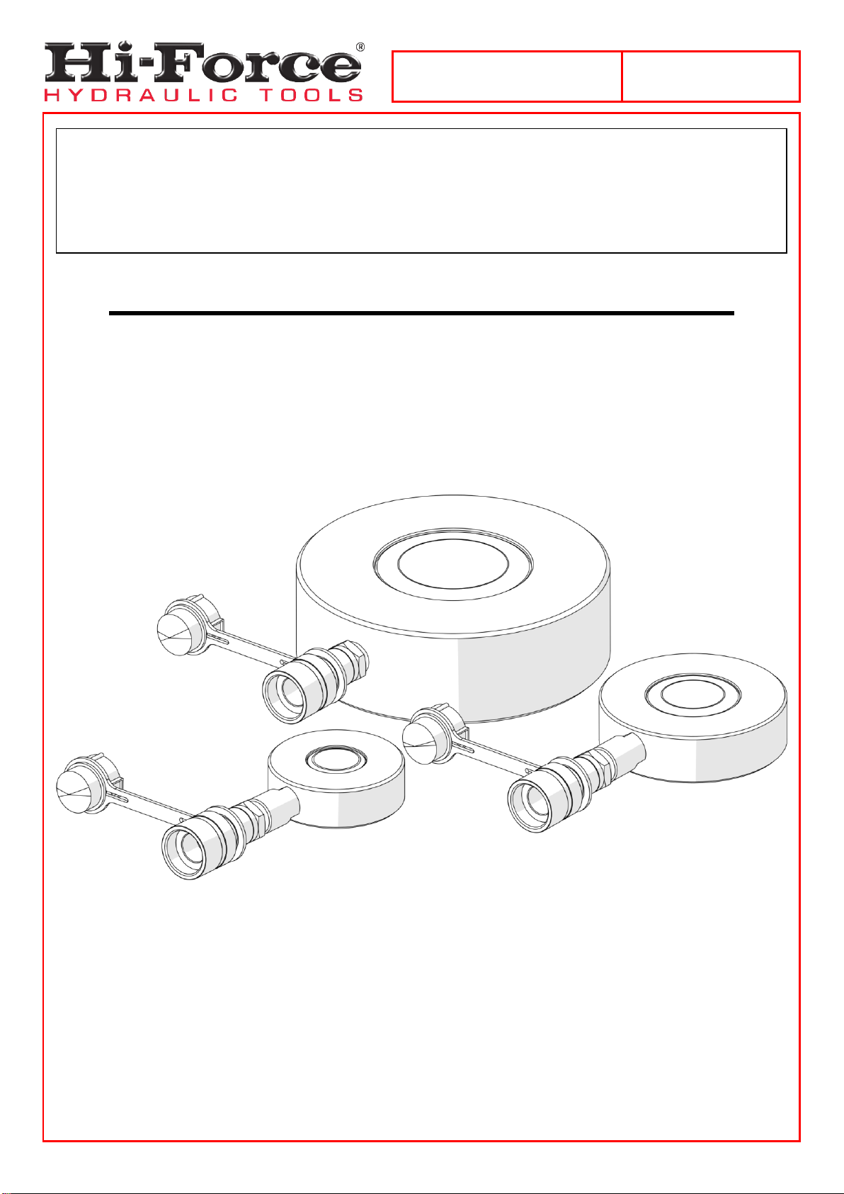
OPERATING INSTRUCTION MANUAL
HVL SERIES | SINGLE-ACTING, VERY LOW HEIGHT
PANCAKE CYLINDERS
Hi-Force HVL Single-Acting, Very Low Height Pancake Cylinders are designed for use in narrow spaces
where a minimal colsed height is required. HVL cylinders are available in capacities ranging from 10 to 104
tonnes with all cylinders having a stroke length of 6mm. All cylinders have a maximum working pressure of
700 bar (10,000 psi). This manual applies to the Hi-Force HVL Single-Acting, Very Low Height Pancake
Cylinders ONLY. It contains the latest product information available at the time of publication and approval.
For information relating to the servicing of an HVL cylinder, see the servicing instructions, which are
available on the Hi-Force website. Hi-Force reserves the right to make changes to this document at any
time without notice.
This ‘Original instructions’ document assumes that the operator carrying out any operation with this
product is trained and competent to do so. This manual does not attempt to cover all details or variations
in the equipment. Nor does thismanual claim to providefor every possible contingency met in connection
with the installation, operation, or maintenance thereof. Should further information be desired, or should
a particular problem arise which is not covered in sufficient detail, the matter should be referred to
Hi-Force.

Operating Instruction Manual:
OM-HVL-01
Serial Numbers:
From: AF0324
2
Table of Contents
1.0 Inspection upon Receipt .................................................................3
2.0 Safety Precautions...........................................................................3
3.0 Declaration of Incorporation/Conformity......................................6
4.0 Component Identification................................................................7
5.0 Installation/Setup ............................................................................8
6.0 Operation........................................................................................10
7.0 Maintenance and Storage..............................................................10
8.0 Specifications.................................................................................11
9.0 System Components/Accessories ..............................................11
10.0 Troubleshooting...........................................................................12
11.0 Contact Details ..................................Error! Bookmark not defined.
NOTE: Images contained within this document are for illustrative purposes ONLY.
Operating Instruction Manual:
OM-HVL-01
Serial Numbers:
From: AF0324
3
1.0 Inspection upon Receipt
Upon receipt of the product, visually inspect the item for any evidence of shipping damage. Please note:
the warranty does not cover shipping damage. Notify the courier immediately if shipping damage is found
and refrain from putting the product into service. The carrier is responsible for repair and replacement costs
resulting from damage that occurred in transit.
2.0 Safety Precautions
2.1 Introduction
Read and follow all the instructions and safety warnings carefully before handling, installation or
use of any hydraulic equipment. Failure to do so could lead to equipment damage, equipment
failure, personal injury or even death. Hi-Force will not be held responsible for any damage to the
equipment, injury or death resulting from the unsafe use of, lack of maintenance to, or incorrect operation
of the product. If in doubt on the correct use of any Hi-Force equipment, contact your nearest Hi-Force office
or distributor. Onlyqualified personnel should be allowed to operate hydraulic equipment. If an operator has
not been trained on high-pressure hydraulic equipment and its safe usage, consult your local Hi-Force sales
office or distributor who can offer training courses for operators.
Failure to observe and obey the following safety precautions could result
in property damage, significant personal injury or death;
2.2 Work Area Safety
Keep work areas clean and well lit. Cluttered spaces and inadequate lighting can result in
unnecessary accidents.
Keep bystanders clear of any hydraulic tool activity. Personnel working in close-range should be
made aware of all high-pressure work before commencing.
Ensure that lifting devices are placed entirely under the load and that lifting is parallel.
2.3 General Hydraulic System Safety Precautions
Failure to observe and obey the following safety precautions could result
in property damage, significant personal injury or death;
When operating any hydraulic equipment, all operators should ensure that all necessary personal
protective equipment (PPE) is worn, as specified by their employer. Steel toe-cap safety shoes,
safetyglasses/visor, and protective gloves should be worn at all times. All relevant risk assessments
should be completed before the use of the equipment.
Keep hydraulic equipment away from open flames and direct heat.

Operating Instruction Manual:
OM-HVL-01
Serial Numbers:
From: AF0324
4
Inspect hoses regularly for damage and wear.
NEVER use hoses that are frayed, kinked, abraded or leaking.
NEVER handle a pressurised hydraulic hose. Hydraulic fluid escaping under pressure from a
ruptured hose can penetrate the skin and lead to a significant medical emergency, and in some
cases, death. Should this incident occur, seek out medical attention immediately.
Seek medical attention immediately if a hydraulic injection injury (no matter how minor) occurs.
The system operating pressure MUST NOT exceed the pressure rating of the lowest-rated
component in the system.
Only use hydraulic cylinders in a complete and tested, coupled system. NEVER attempt to use a
cylinder that is not correctly coupled to its operational pump.
NEVER pressurise an unconnected male coupler/s.
NEVER attempt to disconnect a hose from a hydraulic system until the system's pressure has been
completely released. Doing so can result in that pressure becoming trapped within the system and
relieving trapped pressure can be dangerous.
NEVER try to relieve trapped hydraulic pressure in the system by loosening or attempting to remove
the coupler. Trapped hydraulic pressure can cause a loosened coupler to dislodge unexpectedly
with great force. This action could result in serious personal injury or death.
Loosening a coupler under pressure can result in the escape of hydraulic oil at high pressure, which
can penetrate the skin and cause significant injury or death.
NEVER use a hammer and punch to unseat a coupler check valve that is under pressure. Doing so
could result in the sudden, uncontrolled release of hydraulic oil at high pressure, which could cause
significant injury or death.
NEVER attempt to solve, or clean-up leaks in the system while the system is pressurised.
Immediately replace any worn or damaged parts using genuine Hi-Force parts only.
DO NOT use any hydraulic equipment if you are under the influence of alcohol, drugs or medication.
Lack of attention whilst operating high-pressure hydraulic tools can result in personal injury or death.
Failure to observe and obey the following safety precautions could result
in property damage, equipment damage or minor/moderate personal
injury;
NEVER lift, carry or move any hydraulic components by the hose or hoses connected to them.

Operating Instruction Manual:
OM-HVL-01
Serial Numbers:
From: AF0324
5
Avoid damaging hydraulic hoses. ALWAYS route hoses to ensure that they are free from sharp
bends and kinks. Using a sharply bent or kinked hose will result in severe back-pressure, which can
lead to hose failure.
NEVER use a coupler/s to lift, carry or position a cylinder.
Servicing of hydraulic equipment must only be undertaken by a qualified technician.
DO NOT drop or place heavy objects on a hydraulic hose, as this may cause
internal damage, which could result in rupture of the pressurised hose. A
ruptured hose could cause significant damage to components and possible
severe injury to personal operating nearby.
DO NOT let familiarity gained with any hydraulic equipment allow you to become complacent.
Complacency with any equipment can result in a lack of discipline toward working guidelines and
safety principles.
DO NOT remove any labels from the product. Replace any damaged or unreadable labels
immediately.
2.4 Hydraulic Cylinder Specific Safety Precautions
Failure to observe and obey the following safety precautions could result
in property damage, serious personal injury or death;
DO NOT work under or near a load supported only by hydraulic means. A cylinder, when used as a
lifting device, should not be used as a load-holding device. Once lifted, all loads should be supported
using rigid mechanical structures.
NEVER exceed the maximum rated capacity of any hydraulic equipment. Hi-Force manufactures
HVL hydraulic cylinders to operate at a maximum working pressure of 700 bar (10,000 psi).
Overloading hydraulic cylinders can result in component failure and possible serious personalinjury.
DO NOT connect a hydraulic pump with a higher pressure capacity rating to any Hi-Force cylinder
of this model series.
Good Practice: Use a pressure gauge to monitor the entire system.
ALWAYS make sure that all equipment in the system is in good working condition.
DO NOT weld any items to the cylinder unit or modify it in any way from its delivered condition. Your
warranty may be invalidated, and it could lead to serious personal injury.
NEVER attempt to connect or disconnect a tool/hose/component while the system is under
pressure.

Operating Instruction Manual:
OM-HVL-01
Serial Numbers:
From: AF0324
6
NEVER leave a pressurised system unattended. If you must leave the area, release the pressure
and ensure the hydraulic relief valve on the pump is fully open.
Failure to observe and obey the following safety precautions could result
in property damage, equipment damage or minor/moderate personal
injury;
To protect your warranty, only use the hydraulic oil grades as specified in Section 8.1.
3.0 Declaration of Incorporation/Conformity
Hi-Force declares that this product has been tested and complies with the standards and
declarations as set out in the Declaration of Incorporation/Conformity (DoI/DoC). The DoI/DoC is
included as Annex A to this instruction document and is supplied with all shipments of this
product.

Operating Instruction Manual:
OM-HVL-01
Serial Numbers:
From: AF0324
7
4.0 Component Identification
1
Clyinder Body
4
Female Coupler
2
Piston/Saddle
5
Dust Cap
3
Reducer (Excluding HVL100)
6
Base Plate
Figure 4.1: Component Identification
Operating Instruction Manual:
OM-HVL-01
Serial Numbers:
From: AF0324
8
5.0 Installation/Setup
5.1 Pump Requirements
Ensure that the hydraulic pump to be used is suitable for the cylinder/s to which it will connect. For a
single-acting cylinder (one pressure coupling connection), a single-acting hydraulic pump fitted with either
a 2-way or 3-way valve and a single, correctly rated hose, must be used.
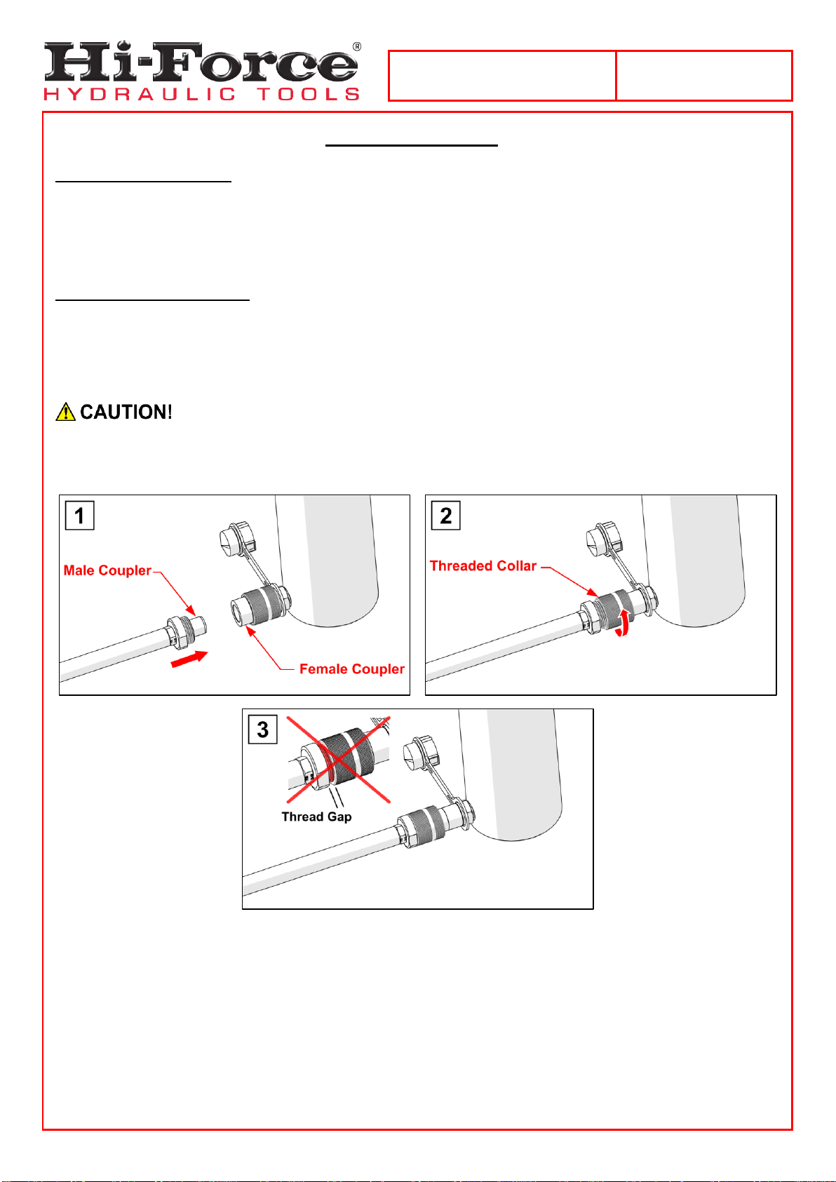
5.2 Hydraulic Connections
Connect the hydraulic hose/s between the cylinder/s and the pump, ensuring that the coupler/s are
fully hand-tightened ONLY. To do so: [1] Press the male coupler into the female coupler (1), [2] then turn
the threaded-collar clockwise (by hand) until the threads are fully engaged.
NEVER use wrenches in an attempt to connect the coupling/s. Incorrectly connected
coupling/s are one of the most common causes of faulty operation.
IMPORTANT: Make sure that all coupler threads are fully engaged. (See figure 5.2, panel 3)
Figure 5.1: Hydraulic Connection

Operating Instruction Manual:
OM-HVL-01
Serial Numbers:
From: AF0324
9
5.3 Bleeding Trapped Air from the System
The bleeding of trapped air from a hydraulic system must only be performed by
qualified personnel who have been trained and are competent to do so.
Cylinders and hoses are not always completely filled with oil when new. It is not usually necessary to bleed
air from single-acting cylinders. However, you MUST ensure that all hydraulic hoses are pre-filled with oil
before connection, to ensure no additional air is introduced into the system.
NEVER extend any HVL cylinder unless its base is fully supported and an external load
is present.
Operating Instruction Manual:
OM-HVL-01
Serial Numbers:
From: AF0324
10
6.0 Operation
A hydraulic pump is required to operate the cylinder range covered in these instructions. Please refer to the
relevant 'Hi-Force hydraulic pump operating instructions' for full details of the chosen pumps applicable
operating instructions.
Single-acting cylinders have 2-different methods of return of the piston. They are either spring-assisted
return or load-assisted return. HVL cylinders are load-assisted return.
Operating Orientation
Hi-Force HVL cylinders can operate in any orientation.
When lowering loads, the load may descendfaster than expected. For precise lowering
control, Hi-Force recommends the use of a manual check valve (HM1C).
ALWAYS ensure the cylinders piston contacts the load to be lifted as squarely as
possible.
NEVER extend any HVL cylinder unless its base is fully supported and an external load
is present.
7.0 Maintenance and Storage
Carry out basic maintenance on a regular basis to keep the cylinder operating in a trouble-free manner.
Maintenance intervals are determined by the frequency of use and the operating conditions on site.
ALWAYS use Hi-Force specified hydraulic oil grades with the cylinders. The use of other fluids may
invalidate your warranty.
After use, always retract the cylinder/s fully before disconnecting the hose/s.
Fit dust caps (5) to the couplers, every time disconnections are made.
Regularly inspect (before and after every use) the cylinder and all accessories for damage.
Inspect the cylinder periodically for paint damage. Clean and touch up any exposed surfaces to
prevent corrosion.
Inspect hoses regularly for damage and wear. DO NOT use hoses that are frayed, abraded or
leaking.
Make sure the cylinder is clean before placing it into storage. Remove any dirt or debris which may
have been picked up while on site.
Store the cylinder/s in a clean and dry environment.
If storage is to be for a prolonged period, it is advisable to apply grease to exposed metal surfaces.
NEVER store, transport or lift a cylinder with its piston in the extended position.
Operating Instruction Manual:
OM-HVL-01
Serial Numbers:
From: AF0324
11
8.0 Specifications
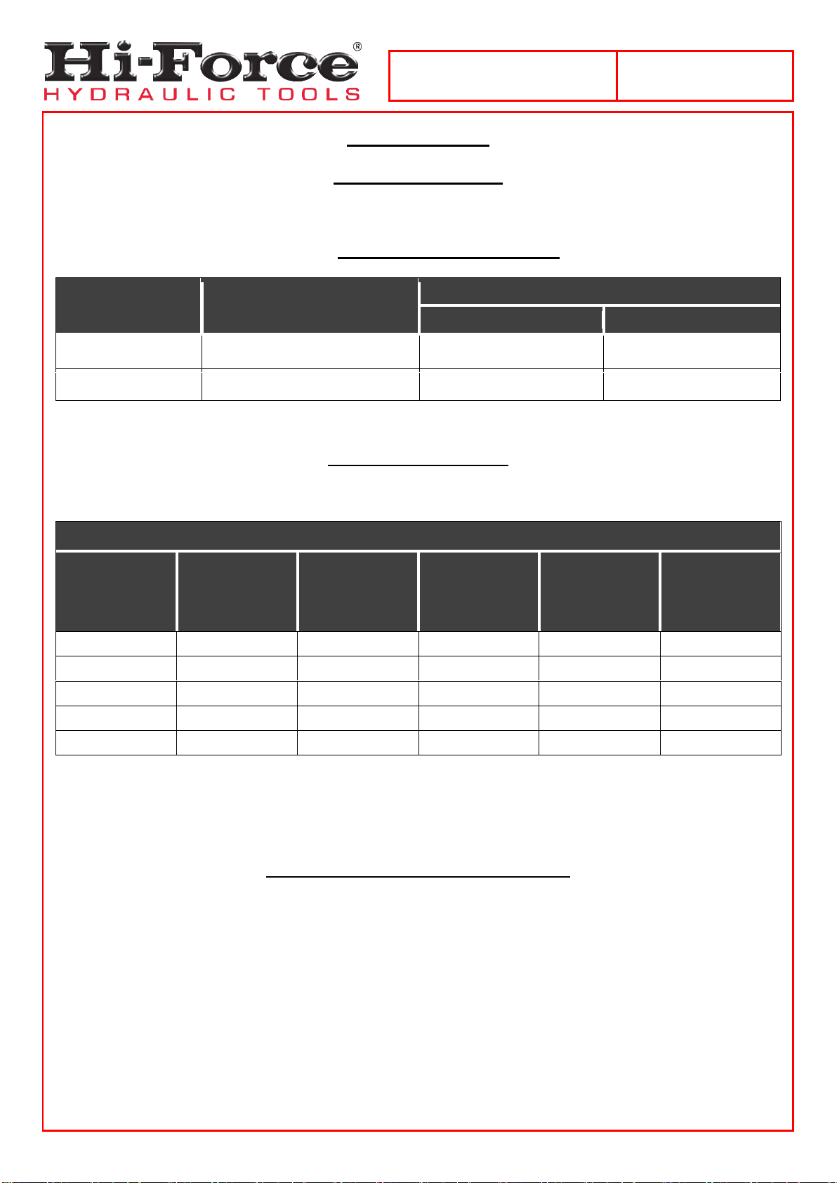
8.1 Oil Specifications
Hi-Force tools will use 1 of 2 grades of oil, dependant on the pump used. The tools are designed to operate
at temperatures between -20°C and 80°C. Details of the oil used can be found in the chosen Hi-Force
pump’s operating manual, in the section: FILLING THE PUMP WITH OIL.
Hi-Force
Model Number
ISO Hydraulic Oil Grade
Temperature Range: Degrees Celcius (°C)
From:
To:
HFO15
ISO15
-23
44
HFO46
ISO46
-2
73
8.2 HVL Specifications
Refer to the engraved detail on the cylinder for model identification.
HVL │SINGLE-ACTING, VERY LOW HEIGHT PANCAKE CYLINDERS
Model
Number
Capacity
(tonnes)
Stroke
(mm)
Oil Capacity
(cm3)
Cylinder eff.
Area
(cm2)
Weight
(kg)
HVL10
10
6
9
14.4
1.6
HVL20
20
6
17
28.6
2.6
HVL30
32
6
27
45.6
3.0
HVL50
50
6
43
71.3
7.2
HVL100
104
6
88
146.5
15.6
9.0 System Components/Accessories
(Refer to the Hi-Force website or latest Hi-Force catalogue for further details)
High-Pressure Hydraulic Hoses
Manifolds and Manifold Assemblies.
Flow Control Valve
Pressure Gauges and Gauge Mounting Blocks
High-Pressure Couplers and Fittings
Operating Instruction Manual:
OM-HVL-01
Serial Numbers:
From: AF0324
12
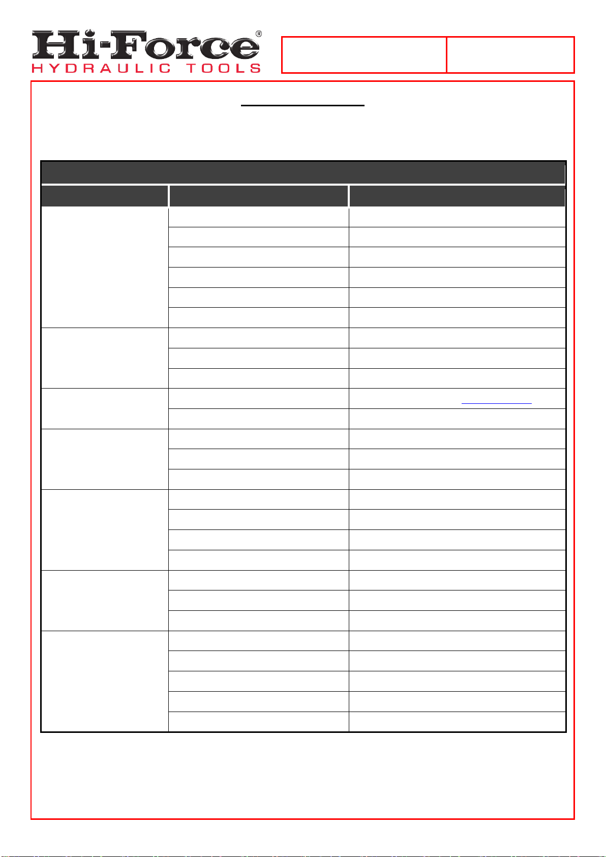
10.0 Troubleshooting
The Hi-Force HVL electric-driven hydraulic pump should be serviced and repaired only by authorised Hi-
Force repair centres. The following table gives possible causes and solutions for common problems.
TROUBLESHOOTING GUIDE
Problem
Possible Cause
Solution
1. Piston will not
advance.
a. Pump release valve open.
Close pump release valve.
b. Coupler not fully tightened.
Tighten coupler.
c. Oil level in pump is low.
Add oil to pump reservoir.
d. Pump malfunctioning.
Repair or replace pump.
e. Load is too heavy for cylinder.
Use correctly rated cylinder for load.
f. Cylinder seals leaking.
Repair or replace cylinder.
2. Cylinder advances part
way.
a. Oil level in pump is low.
Add oil to pump reservoir.
b. Coupler not fully tightened.
Tighten coupler.
c. Cylinder piston binding.
Repair or replace cylinder.
3. Cylinder advances in
spurts.
a. Air in hydraulic system.
Bleed air from system. (See section 5.3)
b. Cylinder piston binding.
Repair or replace cylinder.
4. Cylinder advances
slower than normal.
a. Leaking connection.
Replace faulty component.
b. Coupler not fully tightened.
Tighten coupler.
c. Pump malfunctioning.
Repair or replace pump.
5. Cylinder advances, but
will not hold.
a. Pump malfunctioning.
Repair or replace pump.
b. Leaking connection.
Replace faulty component.
c. Incorrect system setup.
Check system setup.
d. Cylinder seals leaking.
Repair or replace cylinder.
6. Cylinder leaks oil.
a. Worn or damaged seals.
Repair or replace cylinder.
b. Internal cylinder damage.
Repair or replace cylinder.
c. Loose connection.
Tighten or repair connection.
7. Cylinder will not retract
or retracts slower than
normal.
a. Pump release valve is closed.
Open pump release valve.
b. Coupler not fully tightened.
Tighten coupler.
c. Pump reservoir over-filled.
Drain excess oil from pump reservoir.
d. Narrow hose restricting flow.
Replace with larger diameter hose.
e. Cylinder damaged internally.
Repair or replace cylinder.

Operating Instruction Manual:
OM-HVL-01
Serial Numbers:
From: AF0324
13
UK Head Office:
Hi-Force Limited
Prospect Way, Daventry, Northamptonshire
NN11 8PL
United Kingdom
Tel: + 44 1327 301000
Fax: + 44 1327 706555
Email: [email protected]
GLOBAL BRAND. LOCAL SERVICE. www.hi-force.com
Hi-Force Global offices: www.hi-force.com/en-uk/hi-force-offices
Other manuals for HVL Series
1
This manual suits for next models
5
Table of contents
Other Hi-Force Industrial Equipment manuals


