Bison VERSADJUST Installation guide

UNDERSTANDING THE VERSADJUST Patent and Patent Improvements Pending
2 ¼”- 2 ¾” 9 ¾” - 13 ¾”
V1 V4 + VC2 Quick Clip Coupler
CAVITY HEIGHT
2 ¾”- 3 ¾”
V2
3 ¾”- 5 ¾”
V3
5 ¾”- 9 ¾”
V4 Maximum Height 24”
V4 + 4 ea VC2
V Top
VC2 Coupler (Works with Model V4 Only.)
V Base
V Tab 1/8” standard or 3/16” optional
Place Spacer Tab on top of pedestal
To remove tabs:
strike with hammer from above
Comes screwed into V Base Unit. Unscrew top
until “engagement” bumps are felt and heard.
DO NOT extend beyond bumps EXCEPT to add
a coupler to Model V4.
To Assemble:
Align lines on coupler and base
Align tab with Quick Connect slot.
Slide together until tab locks into place.
To Separate:
Hook C2 Coupler Release Tool into slots on the
side of the coupler, detach tool & pull apart.
Comes screwed into V Top Unit. Unscrew top
until “engagement” bumps are felt and heard.
DO NOT extend beyond bumps EXCEPT to add
a coupler to Model V4.
VB Leveller Base
Built-in base 0 - ½” (4%) slope compensation.
The Versadjust, adjustable V-Series line reaches
heights from 2 ¼ inches to 24 inches, has a 1500
pound weight bearing capacity and contains built in
slope compensation from zero to one half inch per
foot slope. Accessories are available to compensate
for additional slope and accommodate heights from
1/8 inch to 2 ¼ inches.
Precise spacer tabs allow for deck drainage,
and the screw-to-adjust height setting assures
a perfectly straight and level deck. Quick clip cou-
plers© (patent pending) increase the speed and
efficiency installing pedestals at heights over 9 ¾
inches. Accessories are available to compensate for
additional slope and accommodate low heights from
1/8 inch to 2 ¼ inches.
The Bison Versadjust pedestal has a broad footprint
that provides stability, is impervious to freeze thaw
cycles, and offers a range of heights suited to almost
any application.
BUILT IN SLOPE BASE COMPENSATION
Each V-Series pedestal comes with base slope
compensation for up to 1/2” per foot (4%) slope.
Slope Adjustment:
Point each finger tab downhill for 1/2” per foot (4%) slope.
Rotate base pieces for precise slope compensation.
To create a flat base:
Position finger tabs opposite one another.
To Remove VB Base Leveller:
Slide pedestal base out of VB base leveller
For additional slope compensation:
A maximum of two (2) Model LD4 base levellers can be
used with the V-Series adding an additional 1/2” per foot
(4%) slope for a total of 1 inch per foot (0-8%) slope. Each
LD4 adds an 3/8” to the overall height of the pedestal.
ROTATE
90°
Finger tab
1975 W. 13th Ave Denver, CO 80204
Phone: 800-333-4234 | Email: info@BisonIP.com
Online: www.BisonIP.com
INSTALLATION DETAILS
Copyright 3-1-2010 United Construction Products, Inc. All Rights
MARCH 2010
BISON INNOVATIVE PRODUCTS
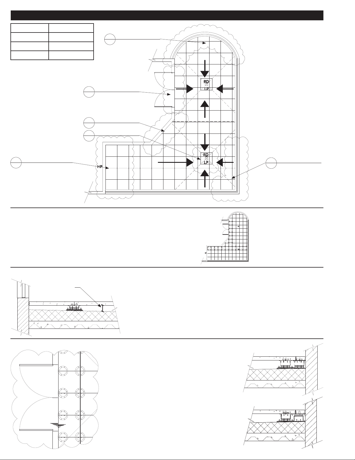
ADVANCED LAYOUT AND PEDESTAL PLACEMENT
Acronym Definition
LP Low Point
HP High Point
RD Roof Drain
A1 THRESHOLD PLACEMENT
A1 RADIUS PLACEMENT
A1 DIAGONAL PLACEMENT
A1 LOW ELEVATION PLACEMENT
A1 DRAIN PLACEMENT
A1 PERIMETER PLACEMENT
“T” METHOD INSTALLATION
1. Determine cavity height at all thresholds, drains and high points.
2. Deduct thickness of decking material.
3. Mark top of pedestal elevation around deck with laser level
4. Plan paver/pedestal layout pattern
5. Install “T” shaped portion of deck starting from threshold or high point
6. Adjust to correct height and level.
7. Installation on both sides of the “T” can proceed.
THRESHOLD AND PERIMETER PLACEMENT
DETERMINING CAVITY HEIGHT
The cavity height is the space between the top of the roofing membrane,
and the bottom of the decking material.
This is the height the pedestal will cover.
Use of a laser level or chalk line may assist.
Also refer to the detachable measuring device printed on the box.
CAVITY HEIGHT
Remove tabs as necessary to inset edge pedestals.
Turn pedestal upside-down or trim the base for tight
fits.
Never allow more than 1 tab width between the
decking material and your containment.
Pedestals may be inverted for particularly tight fits.
Excess tabs may be glued into place with construc-
tion adhesive to ensure spacing when “normal” tab
placement is not possible.
Copyright 3-1-2010 United Construction Products, Inc. All Rights

RADIUS PLACEMENT
DRAIN PLACEMENT
LOW ELEVATION PLACEMENT
Use extra pedestals under triangular pieces to
prevent rocking.
Never allow more than 1 tab width between the
decking material and your containment.
Add an extra pedestal at perimeter bends.
Remove extra tabs to inset pedestals on edge.
Adhere small pavers to top of ped-
estal with construction adhesive.
Turn pedestal upside-down or trim
pedestal base as needed to fit
around perimeter.
Use removed tabs to maintain spac-
ing between pavers.
DIAGONAL PLACEMENT
Adhere small pavers to top of pedestal with
construction adhesive.
Trim pedestal base as needed to fit around
perimeter.
Use removed tabs to maintain spacing between
pavers.
Use extra pedestals under triangular pieces to prevent rocking.
Never allow more than 1 tab width between the decking material and
your containment.
Remove extra tabs to inset pedestals on edge.
Elevate a steel plate or spare paver above the drain, but below the deck itself.
Use that elevated paver to support a pedestal where you need for the deck above.
Copyright 3-1-2010 United Construction Products, Inc. All Rights
For low elevations the following pedestals are available:
LOW HEIGHT PEDESTALS
Model:
VT18 or VT316
HD25
Height:
1/8”
1/4”
HD50
HD75
LO
1/2”
3/4”
1¼ - 2”
Shims can also be used to accomodate variations in height,
in either 1/8” (PS1) or 1/16” (B11) increments.

Copyright 3-1-2010 United Construction Products, Inc. All Rights Reserved
BisonVersadjustDetailsMARCH2010.pdf | 3/2010 Last update
B11s may be placed on top of pedestals to accommodate
for minor leveling of pavers with thickness variations. Use
no more than 2 shims. If using only 1/4 segment, adhere
it to the pedestal with construction adhesive.
B11 (1/16”) SHIMS
SHIMS UNDER PEDESTALS
Place shims (whole or in segments) under the pedestal in a
stairstep fashion to compensate for sloping substrates. Use only
B11 shims for this application. Use no more that four (4) shims.
WORKING WITH SHIMS
PS1 (1/8”) SHIMS
PS1s may be placed on top of pedestals to accommodate
for minor leveling of pavers with thickness variations. Use
no more than 2 shims. If using only 1/4 segment, adhere
it to the pedestal with construction adhesive.
Patent and Patent Improvements Pending
PEDESTAL BASE PADS
Floating Insulation Base (FIB)
If integral roof insulation is installed immediately below
the membrane, the type and density of the insulation is
of utmost importance. Roofing systems having “common”
insulations with a medium density of 20 psi must also use
Bison Floating Insulation Bases (FIB). FIBs are installed
immediately below the Bison Deck Support pedestals to
disperse the deck load. FIB’s are not needed over systems
using 60 psi insulation.
Do not use Bison Deck Supports over any
insulation less than 20 psi or with low density
polystyrene (bead board) insulation.
Floating Foundation Base (FFB)
Bison Floating Foundation Bases (FFB) must be used
beneath all on grade Bison Deck Support decks. Level
the surface and set directly on grade as a base.
Routine maintenance of your paver deck system will enhance the beauty, reduce major repairs, and prolong the life of
your deck. Below is a list of maintenance guidelines that should be performed on a regular basis:
1. Check for “rocking” pavers. If you notice pavers rocking back and forth while walking on the deck simply lift paver up
and shim 1 or more corners until paver is level on all four corners. To ensure pedestal stability, make sure “engagement
bumps” are engaged. Bison B11 (1/16”) or PS1 (1/8”) shims can be ordered and shipped.
2. Depending on substrate materials some settling and or deflection can occur. Remove paver and adjust the pedestal by
turning the base until level height is achieved. You may need to do this on more than one pedestal to level out an area.
3. Clean drains and scuppers on a regular basis. Water should completely drain off roof deck within 48 hours after rainfall,
under ambient drying conditions. Sitting or “ponding” water can be detrimental to deck systems.
4. Periodically check spacer tabs between pavers and replace broken spacer tabs immediately. Loss of spacer tabs can
cause unsafe deck movement.
5. Make sure the edge restraint stays intact and in good condition. There should not be room around perimeters of the
deck in excess of one tab width which would cause lateral movement of pavers, and void the Bison warranty.
6. Follow paver manufacturers’ suggestions for upkeep and maintenance of pavers.
MAINTENANCE GUIDE
Other Bison Industrial Equipment manuals


Popular Industrial Equipment manuals by other brands


Hix
Hix Halux 1200 owner's manual

Genie
Genie RAIL EXTENSION KIT Supplement Instructions

John Crane
John Crane A Series Fitting & Maintenance Instructions

ITW
ITW SIMCO ION IQ Power Installation and operating instructions

Panasonic
Panasonic Aicure UD40 Series user manual

Des Champs Technologies
Des Champs Technologies HVAC Air-Trap P Series Installation, operation and maintenance manual