PI S-340 User manual

Physik Instrumente (PI) GmbH & Co. KG, Auf der Roemerstrasse 1, 76228 Karlsruhe, Germany
Phone +49 721 4846-0, Fax +49 721 4846-1019, Email info@pi.ws, www.pi.ws
PZ75E
S-340 Tip/Tilt Platform
User Manual
Version: 3.0.1
Date: 02.12.2020
This document describes the following products:
S-340.x0L
Tip/tilt platform, 2 mrad, open-loop, LEMO
connectors
S-340.xSL
Tip/tilt platform, 2 mrad, SGS, LEMO
connectors
S-340.xSD
Tip/tilt platform, 2 mrad, SGS, D-sub connector
The letter "x" stands for the respective model:
A: Aluminum cover plate
I: Invar cover plate

The following company names and brands are registered trademarks of Physik Instrumente (PI) GmbH & Co.
KG:
PI®, NanoCube®, PICMA®, PILine®, NEXLINE®, PiezoWalk®, NEXACT®, Picoactuator®, PInano®, PIMag®,
Q-Motion®
The patents held by PI are found in our patent list: https://www.physikinstrumente.com/en/about-pi/patents
© 2020 Physik Instrumente (PI) GmbH & Co. KG, Karlsruhe, Germany. The text, photographs, and drawings in
this manual are protected by copyright. With regard thereto, Physik Instrumente (PI) GmbH & Co. KG retains
all the rights. The use of any text, images and drawings is permitted only in part and only when indicating the
source.
Original instructions
First printing: 02.12.2020
Document number: PZ75E, CBo, Version 3.0.1
Subject to change without notice. This manual is superseded by any new release. The latest release is available
for download (p. 3) on our website.

1About this Document 1
1.1 Objective and Target Audience of this User Manual.................................................. 1
1.2 Symbols and Typographic Conventions...................................................................... 1
1.3 Figures ........................................................................................................................ 2
1.4 Other Applicable Documents ..................................................................................... 2
1.5 Downloading Manuals................................................................................................ 3
2Safety 5
2.1 Intended Use .............................................................................................................. 5
2.2 General Safety Instructions ........................................................................................ 5
2.3 Organizational Measures............................................................................................ 6
3Product Description 7
3.1 Model Overview ......................................................................................................... 7
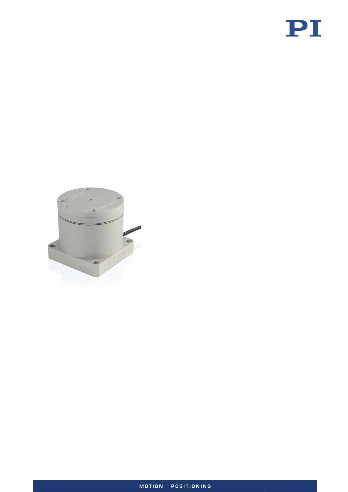
3.2 Product View .............................................................................................................. 8
3.3 Product Labeling......................................................................................................... 9
3.4 Scope of Delivery...................................................................................................... 11
3.5 Accessories ............................................................................................................... 12
3.6 Suitable Electronics .................................................................................................. 12
3.7 Control...................................................................................................................... 14
3.8 Dynamic Behavior..................................................................................................... 15
3.8.1 Calculating Moments of Inertia for Mirror and Mirror Holder.................... 16
3.8.2 Calculating the Resonant Frequency of the Tip/Tilt Platform..................... 19
4Unpacking 21
5Installation 23
5.1 General Notes on Installation................................................................................... 23
5.2 Mounting the Mirror on the S-340........................................................................... 25
5.3 Mounting the S-340.................................................................................................. 29
5.4 Connecting the S-340 to the Protective Earth Conductor........................................ 30
5.5 Connecting the S-340 to the Electronics .................................................................. 31
6Starting and Operating 33
6.1 General Notes on Starting and Operating................................................................ 33
6.2 Operating the S-340 ................................................................................................. 34
6.3 Discharging the S-340............................................................................................... 35
Contents

7Maintenance 37
7.1 General Notes on Maintenance ............................................................................... 37
7.2 Cleaning the S-340.................................................................................................... 37
8Troubleshooting 39
9Customer Service 41
10 Technical Data 43
10.1 Specifications............................................................................................................ 43
10.1.1 Data Table.................................................................................................... 43
10.1.2 Maximum Ratings........................................................................................ 44
10.1.3 Ambient Conditions and Classifications ...................................................... 45
10.1.4 Recommended Control Signals for Dynamic Operation.............................. 45
10.2 Dimensions ............................................................................................................... 46
10.3 Torque for Stainless Steel Screws (A2-70)................................................................ 48
10.4 Pin Assignment ......................................................................................................... 48
10.4.1 D-sub 25 Connector (m) .............................................................................. 48
10.4.2 S-330.DLx Adapter Cable (Only for S-340.xxL)............................................. 49
11 Old Equipment Disposal 53
12 EU Declaration of Conformity 55

1 About this Document
S-340 Tip/Tilt Platform PZ75E Version: 3.0.1 1
In this Chapter
Objective and Target Audience of this User Manual..................................................................... 1
Symbols and Typographic Conventions ......................................................................................... 1
Figures............................................................................................................................................ 2
Other Applicable Documents......................................................................................................... 2
Downloading Manuals ................................................................................................................... 3
1.1 Objective and Target Audience of this User Manual
This user manual contains the information required for using the S-340 as intended.
Basic knowledge of servo systems, drive technologies, and suitable safety measures is assumed.
1.2 Symbols and Typographic Conventions
The following symbols and typographic conventions are used in this user manual:
CAUTION
Dangerous situation
Failure to comply could lead to minor injury.
Precautionary measures for avoiding the risk.
NOTICE
Dangerous situation
Failure to comply could cause damage to equipment.
Precautionary measures for avoiding the risk.
INFORMATION
Information for easier handling, tricks, tips, etc.
1
About this Document

1 About this Document
2 Version: 3.0.1 PZ75E S-340 Tip/Tilt Platform
Symbol/
Label
Meaning
1.
2.
Action consisting of several steps with strict sequential order
Action consisting of one or more steps without relevant sequential
order.
Bullet
p. 5
Cross-reference to page 5
RS-232
Label on the product indicating an operating element (example:
RS-232 interface socket)
Warning signs attached to the product that refer to detailed
information in this manual.
1.3 Figures
For better understandability, the colors, proportions, and degree of detail in illustrations can
deviate from the actual circumstances. Photographic illustrations may also differ and must not
be seen as guaranteed properties.
1.4 Other Applicable Documents
The devices and software tools from PI mentioned in this documentation are described in
separate manuals.
Product Document
E-509.S3 sensor/servo controller module
PZ77E User Manual
E-503.00S piezo amplifier module
PZ62E User Manual
E-505.00 piezo amplifier module
E-505.00S offset voltage source for tip/tilt
platforms
E-501.00 9.5" housing for modular piezo
controller system
E-501.00 19" housing for modular piezo
controller system, 1 to 3 channels
E-518.I3 interface module
E518T0001 User Manual
E-616 multi-channel servo controller for
piezo tip/tilt mirrors
PZ219 User Manual
PZ200 User Manual
E-727.xF digital multi-channel piezo
controller with EtherCAT
E727T0005 User Manual
E-727.x • E-727.xAP digital multi-channel
piezo controller
E727T0005 User Manual
The latest versions of the user manuals are available on our website for download (p. 3).

1 About this Document
S-340 Tip/Tilt Platform PZ75E Version: 3.0.1 3
1.5 Downloading Manuals
INFORMATION
If a manual is missing or problems occur with downloading:
Contact our customer service department (p. 41).
Downloading manuals
1. Open the website www.pi.ws.
2. Search the website for the product number (e.g., S-340) or the product family (e.g.,
tip/tilt platform).
3. Click the corresponding product to open the product detail page.
4. Click the Downloads tab.
The manuals are shown under Documentation. Software manuals are shown under
General Software Documentation.
5. Click the desired manual and fill out the inquiry form.
The download link will then be sent to the email address entered.


2 Safety
S-340 Tip/Tilt Platform PZ75E Version: 3.0.1 5
In this Chapter
Intended Use.................................................................................................................................. 5
General Safety Instructions............................................................................................................ 5
Organizational Measures............................................................................................................... 6
2.1 Intended Use
The S-340 is a laboratory device as defined by DIN EN 61010-1. It is intended for indoor use and
use in an environment that is free of dirt, oil, and lubricants.
In accordance with its design, the S-340 is intended for precision positioning and alignment of a
mirror in two orthogonal axes with a common pivot point (parallel kinematics). The S-340 is
suitable for highly dynamic applications and can be mounted in any orientation.
The S-340 is dispatched without a mirror and is intended to be used for attaching a suitable
mirror (p. 25).
The S-340 can only be used as intended in conjunction with suitable electronics (p. 12) available
from PI. The electronics are not included in the S-340's scope of delivery.
The electronics must provide the required operating voltages. To operate the S-340.xSx models
(p. 7) the electronics must also be able to read out and process the signals from the strain
gauge sensors to ensure proper performance of the servo control system.
2.2 General Safety Instructions
The S-340 is built according to state-of-the-art technology and recognized safety standards.
Improper use can result in personal injury and/or damage to the S-340.
Use the S-340 for its intended purpose only, and only when it is in perfect technical
condition.
Read the user manual.
Eliminate any malfunctions that may affect safety immediately.
The operator is responsible for the correct installation and operation of the S-340.
2
Safety

2 Safety
6 Version: 3.0.1 PZ75E S-340 Tip/Tilt Platform
2.3 Organizational Measures
User manual
Always keep this user manual together with the S-340.
The latest versions of the user manuals are available for download (p. 3) on our
website.
Add all information from the manufacturer to the user manual, for example
supplements or technical notes.
If you give the S-340 to a third party, include this user manual as well as other relevant
information provided by the manufacturer.
Do the work only if the user manual is complete. Missing information due to an
incomplete user manual can result in minor injury and damage to equipment.
Install and operate the S-340 only after you have read and understood this user manual.
Personnel qualification
The S-340 may only be installed, started, operated, maintained, and cleaned by authorized and
appropriately qualified personnel.

3 Product Description
S-340 Tip/Tilt Platform PZ75E Version: 3.0.1 7
In this Chapter
Model Overview............................................................................................................................. 7
Product View.................................................................................................................................. 8
Product Labeling ............................................................................................................................ 9
Scope of Delivery ......................................................................................................................... 11
Accessories................................................................................................................................... 12
Suitable Electronics...................................................................................................................... 12
Control ......................................................................................................................................... 14
Dynamic Behavior ........................................................................................................................ 15
3.1 Model Overview
Model Description
S-340.A0L
Tip/tilt platform, 2 mrad, open loop, LEMO connectors, aluminum cover plate
S-340.ASL
Tip/tilt platform, 2 mrad, SGS, LEMO connectors, aluminum cover plate
S-340.ASD
Tip/tilt platform, 2 mrad, SGS, D-sub connector, aluminum cover plate
S-340.I0L
Tip/tilt platform, 2 mrad, open loop, LEMO connectors, Invar cover plate
S-340.ISL
Tip/tilt platform, 2 mrad, SGS, LEMO connectors, Invar cover plate
S-340.ISD
Tip/tilt platform, 2 mrad, SGS, D-sub connector, Invar cover plate
For further technical data, see the specifications (p. 43).
3
Product Description

3 Product Description
8 Version: 3.0.1 PZ75E S-340 Tip/Tilt Platform
3.2 Product View
Figure 1: Exemplary product view of an S-340
1Platform
2Flexure
3Housing, consisting of
3a: Housing tube
3b: Base
4Protective earth connector
5D-Sub 25 connector

3 Product Description
S-340 Tip/Tilt Platform PZ75E Version: 3.0.1 9
Figure 2: S-340: Schematic view of the motion axes with positive direction of motion
θ
X
: Tilt axis 1
θY: Tilt axis 2
The arrows indicate the positive direction of motion of the respective axis.
3.3 Product Labeling
Labeling Description
S-340.ASD
Product name (example), the characters following the period refer to
the model
123456789
Serial number (example), individual for each S-340
Meaning of each position (from the left):
1 = internal information
2 and 3 = year of manufacture
4 to 9 = consecutive number
Manufacturer's logo
Country of origin:
Germany
Country of origin
Warning sign "Pay attention to the manual!"
Old equipment disposal (p. 53)
CE conformity mark
WWW.PI.WS
Manufacturer's address (website)
Symbol for the protective earth conductor, marks the protective earth
connection of the S-340 (p. 30)

3 Product Description
10 Version: 3.0.1 PZ75E S-340 Tip/Tilt Platform
Labeling of the D-sub 25 connector
Figure 3: D-sub 25 connector on the connecting cable of the S-340
"Residual Voltage" warning sign:
Indicates risk of electric shock (p. 5)
Labeling of the S-330.DLS adapter cable for S-340.xSL
Figure 4: S-330.DLS adapter cable: Piezo connectors [1] and sensor connectors [2]
Piezo connectors:
PZT1: Piezo connector for axis 1
PZT2: Piezo connector for axis 2
PZT3: Piezo connector for 100 V fixed voltage
Sensor connectors:
Sensor 1: Sensor connector for axis 1
Sensor 2: Sensor connector for axis 2

3 Product Description
S-340 Tip/Tilt Platform PZ75E Version: 3.0.1 11
Labeling of the S-330.DL0 adapter cable for S-340.x0L
Figure 5: S-330.DL0 adapter cable: Piezo connectors [1]
Piezo connectors:
CH1: Piezo connector for axis 1
CH2: Piezo connector for axis 2
CH3: Piezo connector for 100 V fixed voltage
3.4 Scope of Delivery
Product number Description
S-340
Tip/tilt platform according to order (p. 7)
000036450
M4 screw set for protective earth, consisting of:
1 flat-head screw with cross recess, M4x8, ISO 7045
2 lock washers
2 flat washers
PZ277EK
Printed short instructions for S-3xx piezo tip/tilt platforms
Additional scope of delivery of the S-340.xxL models
S-340.xSL models with position sensor:
Product number Description
S-330.DLS
Adapter cable D-sub 25 to LEMO connectors for piezo tip/tilt mirrors /
platforms, tilt axes with differential drive, with SGS
S-340.x0L models without position sensor:
Product number Description
S-330.DL0
Adapter cable D-sub 25 to LEMO connectors for piezo tip/tilt mirrors /
platforms, tilt axes with differential drive

3 Product Description
12 Version: 3.0.1 PZ75E S-340 Tip/Tilt Platform
3.5 Accessories
Extension cables for S-340.xxL
Product number Description
P-891.01
Extension cable for piezo voltage, LEMO connectors, 1 m
P-891.02
Extension cable for piezo voltage, LEMO connectors, 2 m
P-891.03
Extension cable for piezo voltage, LEMO connectors, 3 m
P-891.05
Extension cable for piezo voltage, LEMO connectors, 5 m
P-891.10
Extension cable for piezo voltage, LEMO connectors, 10 m
P-892.01
Extension cable, for strain gauge sensors, LEMO connectors, 1 m
P-892.02
Extension cable, for strain gauge sensors, LEMO connectors, 2 m
P-892.03
Extension cable, for strain gauge sensors, LEMO connectors, 3 m
P-892.05
Extension cable, for strain gauge sensors, LEMO connectors, 5 m
P-892.10
Extension cable, for strain gauge sensors, LEMO connectors, 10 m
To order, contact our customer service department (p. 41).
3.6 Suitable Electronics
Suitable electronics for the S-340.xxD models
Electronics Description
E-616
Controller for multi-axis piezo tip/tilt mirrors and platforms
E-727.xF*
Digital multi-channel piezo controller with EtherCAT
E-727.x •
E-727.xAP*
Digital multi-channel piezo controller
* With E727B0015 adapter, D-sub 25 (f) to D-sub 37 (m) (included in the scope of delivery if you
ordered the S-340 as system with E-727)
Suitable electronics for the S-340.xxL models
Electronics Description
E-500 • E-501
Modular piezo controller

3 Product Description
S-340 Tip/Tilt Platform PZ75E Version: 3.0.1 13
Suitable configurations for E-500/E-501:
Piezo amplifier module Sensor module
(for S-340.xSL only)
Housing Interfaces
E-503.00S
Piezo amplifier module,
2 channels, -30 to 130 V.
Customized version,
modified for S-330, S-331,
S-340 tip/tilt mirror
systems, with a fixed
voltage of +100 V, two
variable voltages
E-509.S3
Sensor / servo
controller module,
strain gauge
sensors, 3 channels
E-501.00
9.5" housing for
modular piezo
controller system, 1 to
3 channels
Optional: E-518.I3
Interface module,
3 channels, TCP/IP,
USB, and RS-232
interfaces
2 × E-505.00
Piezo amplifier module,
2 A, -30 to 130 V,
1 channel
1 × E-505.00S
Offset voltage source for
tip/tilt platforms, 100 V
fixed voltage
E-509.S3
Sensor / servo
controller module,
strain gauge
sensors, 3 channels
E-500.00
19" housing for
modular piezo
controller system, 1 to
3 channels
Optional: E-518.I3
Interface module,
3 channels, TCP/IP,
USB, and RS-232
interfaces
To order, contact our customer service department (p. 41).

3 Product Description
14 Version: 3.0.1 PZ75E S-340 Tip/Tilt Platform
3.7 Control
Figure 6: Differential drive of the tip/tilt platform, functional principle using the tilting of a single axis
as an example
1Piezo actuator 1 of the axis
2Piezo actuator 2 of the axis
3Platform
The S-340 is a tip/tilt platform with differential piezo drive. Four piezo actuators are
interconnected in pairs to realize tip/tilt motion on two axes.
Both pairs of actuators are electrically switched so that when piezo voltage UPiezo is changed, the
voltage is increased to one actuator of a pair while the voltage to the other actuator is
decreased by the same amount. The actuator with the increased voltage expands while the
other actuator with the decreased voltage contracts. This produces the tip/tilt motion.
For a simplified representation of the functional principle, only one axis is shown in the figure
above. The platform is shown rotated around 0°.
When the control input voltage UIn increases, piezo actuator 1 expands and piezo actuator 2
contracts. This produces a tilt in the positive direction.
Because of the way they are interconnected, both actuator pairs always move in opposite
directions. It is therefore impossible to command linear motion in the Z axis.
The position of the Z axis can change with temperature fluctuations, however: Due to the
symmetrical design of the tip/tilt platform, temperature fluctuations do not cause the platform
to tilt but cause the length of the piezo actuators to change evenly in the direction of the Z axis.

3 Product Description
S-340 Tip/Tilt Platform PZ75E Version: 3.0.1 15
Most applications are not very sensitive to such deviations as long as the tip/tilt angle does not
change.
Each of the four piezo actuators of the S-340 is equipped with a strain gauge sensor. Therefore,
in addition to the amplifier channel, a servo loop with a sensor channel must be available for
each actuator pair.
Example: Behavior of the tip/tilt platform during operation
The tip/tilt platform is in zero position when the electronics are switched off (tilt = 0 mrad).
Switching on the electronics applies a fixed voltage of 100 V, which fully tilts the tip/tilt
platform into the negative direction.
The motion of the tip/tilt platform depends on the control voltage:
Control voltage Behavior of the tip/tilt platform Tip/tilt angle
<50 V Tilt to the negative direction -1 mrad at 0 V
50 V
Zero position (no tilt)
0 mrad at 50 V
>50 V
Tilt to the positive direction
+1 mrad at 100 V
3.8 Dynamic Behavior
The maximum operating frequency of a piezo tip/tilt platform depends on the following factors:
Bandwidth of amplifier, controller, and sensor
Resonant frequency of the tip/tilt platform including mirror and where appropriate,
mirror holder
The resonant frequency is estimated in two steps:
a) Calculating the moments of inertia for mirror and mirror holder (p. 16)
b) Calculating resonant frequency of the tip/tilt platform including mirror and mirror
holder (p. 19)

3 Product Description
16 Version: 3.0.1 PZ75E S-340 Tip/Tilt Platform
3.8.1 Calculating Moments of Inertia for Mirror and Mirror Holder
Calculating the distance from the axis through the center of gravity of the mirror to
the rotational axis
Before the moment of inertia of the mirror is calculated, it is necessary to calculate the distance
from the axis through the center of gravity of the mirror to the rotational axis of the platform.
When a mirror holder is used, it must be included in the calculation.
Figure 7: Example diagram: Platform with mirror holder and mirror
1Mirror
2Axis through the center of gravity of the mirror
3Axis through the center of gravity of the mirror holder
4Mirror holder (example of a geometry)
5Axis through the pivot point of the platform of the S-340 ("rotational axis")
6Platform
Other manuals for S-340
1
This manual suits for next models
6
Table of contents
Other PI Industrial Equipment manuals

PI
PI V-551.2D User manual

PI
PI P-616 NanoCube User manual

PI
PI VT-80 User manual

PI
PI S-340 Manual

PI
PI H-811.D2 Instruction Manual

PI
PI L-412.XX9025E1B Series User manual

PI
PI L-417 9232B Series User manual

PI
PI A-62 Series User manual

PI
PI L-412.XX9232 Series User manual

PI
PI NEXACT Stage N-565 Series User manual
Popular Industrial Equipment manuals by other brands

COMPTROL
COMPTROL DH151 Series instruction manual

Johnson Controls
Johnson Controls DSV060B installation instructions

Belanger
Belanger CUBE Installation and startup guide

CARLO GAVAZZI
CARLO GAVAZZI SCTL55 instruction manual

Fröling
Fröling Turbomat 320 operating instructions

SCHUNK
SCHUNK TRIBOS SVP-2D Assembly and operating manual