Hi-Line ConSEP100 Instructions for use

Instruction and Maintenance Manual
OIL / WATER SEPARATOR
ConSEP 100-1500
ConSEP100-1500
1/15

2/15

INDEX
1. GENERAL INFORMATION
2. TECHNICAL DESCRIPTION
3. INSTALLATION
3.1
Acceptance and transport
3.2
Installation site
3.5
Condensate drain
4. OPERATION
5. MAINTENANCE, DISMANTLING AND SPARE PARTS
5.1
Maintenance
5.2
Dismantling exhausted bags and separator
5.3
Replacement kit
LIST OF ATTACHMENTS
A
Dimensions separators technical features
3.3
Activation of
ConSEP100
,
ConSEP300
,
ConSEP750
and repalcemente filter kit
3.4
Activation of
ConSEP1500
and replacemente filter kit
3/15

1 GENERAL INFORMATION
Symbols applied on the manual
Mandatory consulting the manual
Environmental requirements
Attention
Recyclable materials
This manual has been written to allow staff use oil / water separator in a safety and affactive way. therefore
any installation, use and maintenance operations must be performed respecting the instructions contained
in this manual. Therefore asked to read this manual in its entirety. The manufacturer declines all
responsibility in case the separator is used for purposes other than those for which it was made.
Any installation, use and maintenance operation must be performed by qualified personnel.
The manufacturer will not be liable in case of uses different or nor complying with those foreseen
in this manual.
2 TECHNICAL DESCRIPTION
CODE
DESCRIPTION
CODE
DESCRIPTION
LD
Lid
I3
3rd inlet
CAF
Carbon air filter
PF
Pre-filter
FM
Foam
CF
Carbon filter
BD
Separator body
OT
Outlet
I1
1st inlet
TT
Test connection
I2
2nd inlet
4/15

5/15 Cod. 710.0170.00.00-OWS –Rev.00 –18.12.2014
3 INSTALLATION
3.1 ACCEPTANCE AND TRANSPORTATION
At the moment the customer accepts the delivery, he must fully inspect the dryer to verify its integrity and
the presence of all the items listed in the shipping documentation.
Eventual claims for missing and/or damaged parts must be addressed directly to our facility or to
the closest reseller, within 8 (eight) days from the date on which the goods have been received.
It is mandatory to keep the separator always in vertical position, as indicated by the symbols
present on the packaging.
We suggest to keep the original packaging at list for the duration period of the warranty of the
machine. Anyhow, do not forget to dispose the various materials in compliance with the relevant
rules locally in force.
If not in use, the separator can be stored in its packaging in a dust free and protected site at a maximum
temperature of 50 °C, and a specific humidity non exceeding the 90 %.
3.2 INSTALLATION SITE

While preparing a proper site for the installation of the separator, please take into account the
following requirements:
The separator must be protected from atmospheric agents and not directly exposed to
sun light.
A seating base flat and capable to hold the weight of the separator.
Ambient temperature complying with the nominal data of the separator.
Make sure to leave sufficient clearance around the separator for maintenance and/or
control operations.
KIT
Perform the following steps to correct installation.
1. If present, remove only the plastic bag of activated carbon (CF)
2. Put the activated carbon bag (CF) in a receptacle filled by clear water at least 8 h before connecting
the condensate drain.
3. Place foam (FM), as shown in photo, in the lid (LD) (activity #1); place activated carbon layer (CAF)
above the foam.
place activated the carbon bag or the carbon bags (CF) in separator body (BD) (activity #2), then
white pre-filter bag (PF), (activity #3).
4. Models ConSep100and ConSEP300 are provided by a carbon bag (CF) and a white pre-filter bag
(PF). Model Con SEP750 is provided by 2 carbon bags (CF) and a white pre-filter bag (PF). First
6/15
3.3 ACTIVATION OF ConSEP100-750 AND REPLACEMENTE FILTER

5. Establish inlet connection (I1 or I2) by which connect separator to plant and then fit T joint.
6. Insert lid (LD) as shown in following image.
ConSEP 100-300 ConSEP 750
7/15

7. Insert connector for outlet (OT); then fit drain tube to connector.
8. Insert dedicated screw to close connection test.
Perform the following steps to correct installation.
1. If present, remove only the plastic bag of activated carbon (CF) of both separator.
2. Put the activated carbon bag (CF) of both separator in a receptacle filled by clear water at least 8 h
before connecting the condensate drain.
3. Place foam (FM), as shown in photo, in the lid (LD) (activity #1); place activated carbon layer (CAF)
above the foam. Same operation in both lids.
3.4 ACTIVATION OF ConSEP 1500 AND REPLACEMENT FILTER KIT
ConSEP 1500
8/15

4. Assemble separator as shown on image.
5. Place a carbon bag (CF) in first separator body (activity #2) and both pre-filter bags (PF) in first
separator body (activity #3)
9/15

6. Place 3 activated carbon bags (CF) in second separator body (activity #4)
7. Fit Tee joint to first separator
8. Insert lid (LD) on both separator
10/15

9. Insert connector for outlet (OT); then fit drain tube to connector.
10. Insert dedicated screw to close connection test.
11/15

4. OPERATION
La condensa è introdotta nel separatore attraverso la camera di sfogo della pressione del
coperchio (LD);
la condensa cade poi attraverso un foro del coperchio all’interno del corpo del separatore
(BD);
il sacco pre-filtro (PF) e il sacco a carboni attivi (CF), mediante un processo di filtrazione
per coalescenza e decantazione rendono la condensa pura da particelle d’olio e particelle
solide;
dopo questo processo la condensa può essere scaricata nella rete fognaria oppure
secondo le norme vigenti nello stato di installazione.
5. MAINTENANCE, DISMANTLING ANDSPARES PARTS
5.1 MAINTENANCE
It is recommended to check drain water quality at least once every 6 months. Replace filter bags at least
once every 12 months; replacement of filter bag must be in compliance instruction 4 of paragraph 3.3 for
5.2 DISMANTLING OF EXHAUSTED BAGS AND SEPARATOR
It is recommended to comply law in force for the disposal of all types of materials.
The separator must be disposed of in homogeneous groups of materials.
Dispose of the condensate in the environment..
Components
Material
Foam (FM)
Plastic
Activated carbon air filter (CAF)
Activated carbon
Lid (LD)
Plastic
Body (BD)
Plastic
Pre-filter bag (PF)
Textile
Activated carbon bag (CF)
Activated carbon
5.3 REPLACEMENT KIT RICAMBIO
Separator
Kit Code
Description
separator ConSEP100 - ConSEP750, and in coompliance instructions 5 and 6 for
separator ConSEP1500.
ConSEP750
ConSEP1500
Kit OWS 2550m
ConSEP1500KIT
ConSEP100
ConSEP100KIT
Kit OWS
100cfm
ConSEP300
ConSEP300KIT
Kit OWS
300cfm
ConSEP750KIT
t OWS 1
Kit OWS 750cfm
Kit OWS 1500cfm
12/15

LIST OF
ATTACHEMENTS
13/15

A. DIMENSIONS SEPARATORS TECHNICAL FEATURES SEPARATORS
MODEL
Standard flow rate
A
B
Weight
Connections
I1, I2, I3 e OT
m3/h
l/min
cfm
mm
mm
kg
lbs
inch
170
2833
100
460
290
2,5
5,5
BSP 1/2”
510
8500
300
600
370
3,5
7,7
BSP 1/2”
1275
21250
750
930
500
4,9
10,8
BSP 3/4”
Maximum
ambient
temperature
Maximum air flow
Screw compressor
Piston compressor
TDL
VDL
VCL
PAO
ESTER
VDL
PAO
ESTER
°C
m3/h
31
192
192
154
154
133
134
115
134
45
149
149
119
119
103
104
89
104
31
576
576
461
461
398
403
346
403
45
446
446
357
357
308
312
268
312
31
1441
1441
1153
1153
994
1009
864
1009
45
1116
1116
893
893
770
781
669
781
ConSEP100-750
ConSEP100
ConSEP300
ConSEP750
Mineral oil
Synt
hetic
oil
Mineral oil
Synt
hetic
oil
ConSEP100
38
170
170
136
136
117
119
102
119
ConSEP300
38
510
510
408
408
352
357
306
357
ConSEP750
38
1275
1275
1020
1020
880
893
765
893
14/15

MODEL
Standard flow rate
A
B
Weight
Connections
I1, I2, I3 e OT
m3/h
l/min
cfm
mm
mm
kg
lbs
inch
2550
42500
1500
930
1150
9,8
21,8
BSP 3/4”
Maximum
ambient
temperature
Maximum air flow
Screw compressor
Piston compressor
TDL
VDL
VCL
PAO
ESTER
VDL
PAO
ESTER
°C
m3/h
31
2882
2882
2305
2305
1988
2017
1729
2017
45
2231
2231
1785
1785
1540
1562
1339
1562
ConSEP1500
ConSEP1500
ConSEP1500
38
2550
2550
2040
2040
1760 1785
1530
1785
Mineral oil
Synt
hetic
oil
Mineral oil
Syn
thetic
oil
15/15
This manual suits for next models
3
Table of contents
Popular Water Filtration System manuals by other brands
Cintroclear
Cintroclear UF 400 installation instructions
Clean Water Systems
Clean Water Systems Birm 7800 Installation & start?up guide

Clean Water
Clean Water Living Water VORTEXer user guide

Heylo
Heylo HWA 600 manual
PureFlow AirDog
PureFlow AirDog FP-100 installation manual
EHEIM
EHEIM Aquaball 2206 instructions
Davey
Davey EAFM7 Installation and operating instructions
Acuva
Acuva Eco installation instructions
bluMartin
bluMartin freeAir100 Service
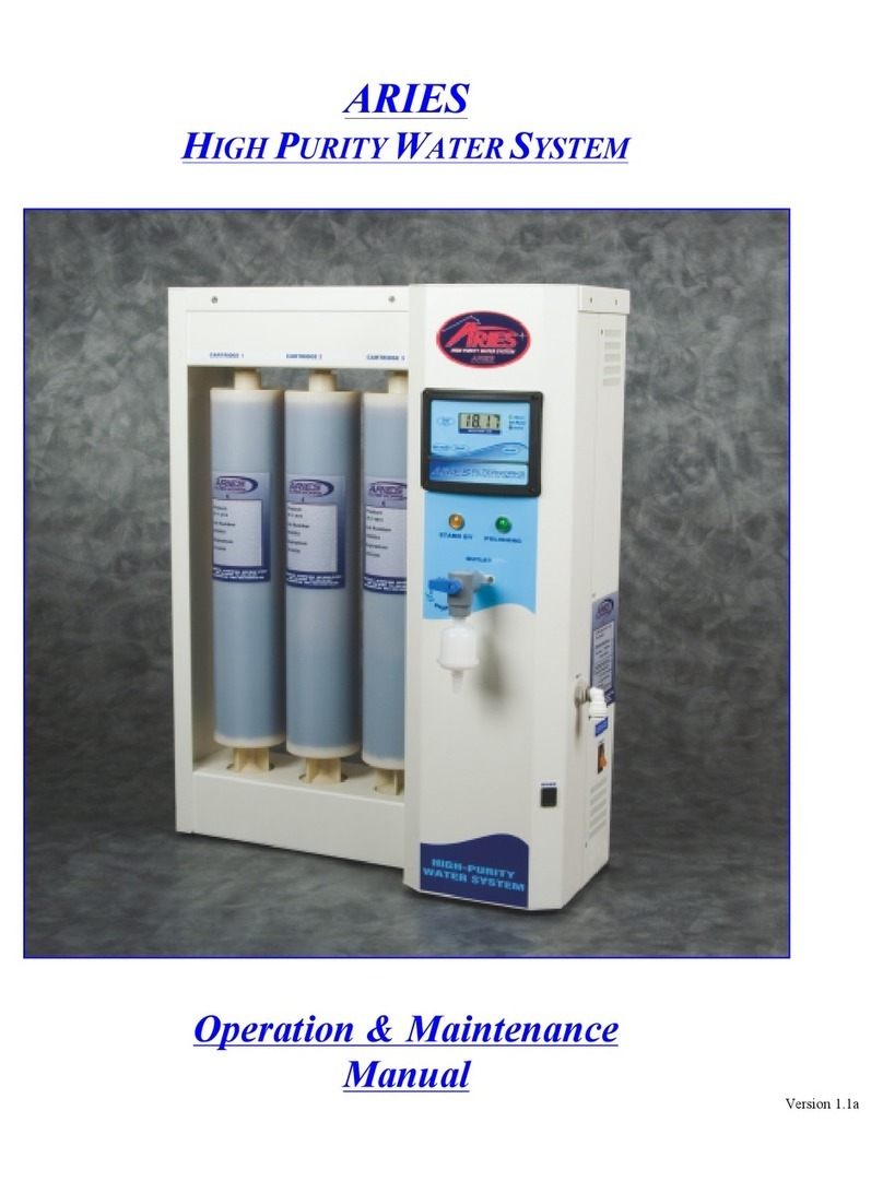
Aries
Aries HIGH PURITY WATER SYSTEM Operation & maintenance manual
Grunbeck
Grunbeck BOXER RX Operation manual
Commodity Axis
Commodity Axis Poly-Reactor ViaAqua PR 20/20 Booklet
