Trion AIR BOSS User manual
*** READ AND SAVE THESE INSTRUCTIONS ***
TRION AIR BOSS
DUST ELIMINATOR
OWNER’S MANUAL
101 McNeill Road •Sanford, NC 27330
(919) 775-2201 •Fax: (919) 774-8771 •(800) 884-0002
www.trioninc.com
MANUAL PART NO. 149739-001 •December 2002

READ AND SAVE THESE INSTRUCTIONS”
WARNING!
TO REDUCE THE RISK OF FIRES, ELECTRICAL SHOCK, OR INJURY TO
PERSONS, OBSERVE THE FOLLOWING:
A. Installation work and electrical wiring must be done by qualified person(s) in accordance
with all applicable codes and standards, including fire-rated construction.
B. When cutting or drilling into wall or ceiling, do not damage electrical wiring and other
hidden utilities.
C. If this unit is to be installed over a tub or shower, it must be marked as appropriate for the
application.
D. Use this unit in the manner intended by the manufacturer. If you have any questions,
contact the manufacturer.
Trion, Inc.
101 McNeill Road
Sanford, North Carolina 27330, U.S.A.
Tel: (919) 775-2201
(800) 884-0002
Fax: (919) 777-6399
Email: [email protected]
Web site: www.trioninc.com
E. Before servicing or cleaning unit, switch power off at service panel and lock service
panel to prevent power from being switched on accidentally.

Table of Contents
Title Page
I. INSTALLATION……………………………………………………………………….. 2
II. SERVICE: CLEANING THE ELIMINATOR PREFILTER………..………………… 4
III. SERVICE: REMOVAL AND REPLACEMENT OF THE HEPA FILTER……………5
IV. SERVICE: REMOVAL AND INSTALLATION OF THE MOTOR…………………..6
V. ON/OFF SWITCH-SPEED/AIRFLOW ADJUSTMENTS……………………………...8
VI. TROUBLE SHOOTING…………………………………………………………………9
VII. ELIMINATOR WIRING DIAGRAMS…………………………………………………10
VIII. ELIMINATOR REPLACEMENT PARTS LIST………………………….…………….11
IX. WARRANTY……………………………………………………………………………12
X. TESTING…………………………………………………………….………………….13
ELIMINATOR OWNER’S MANUAL
Page 1

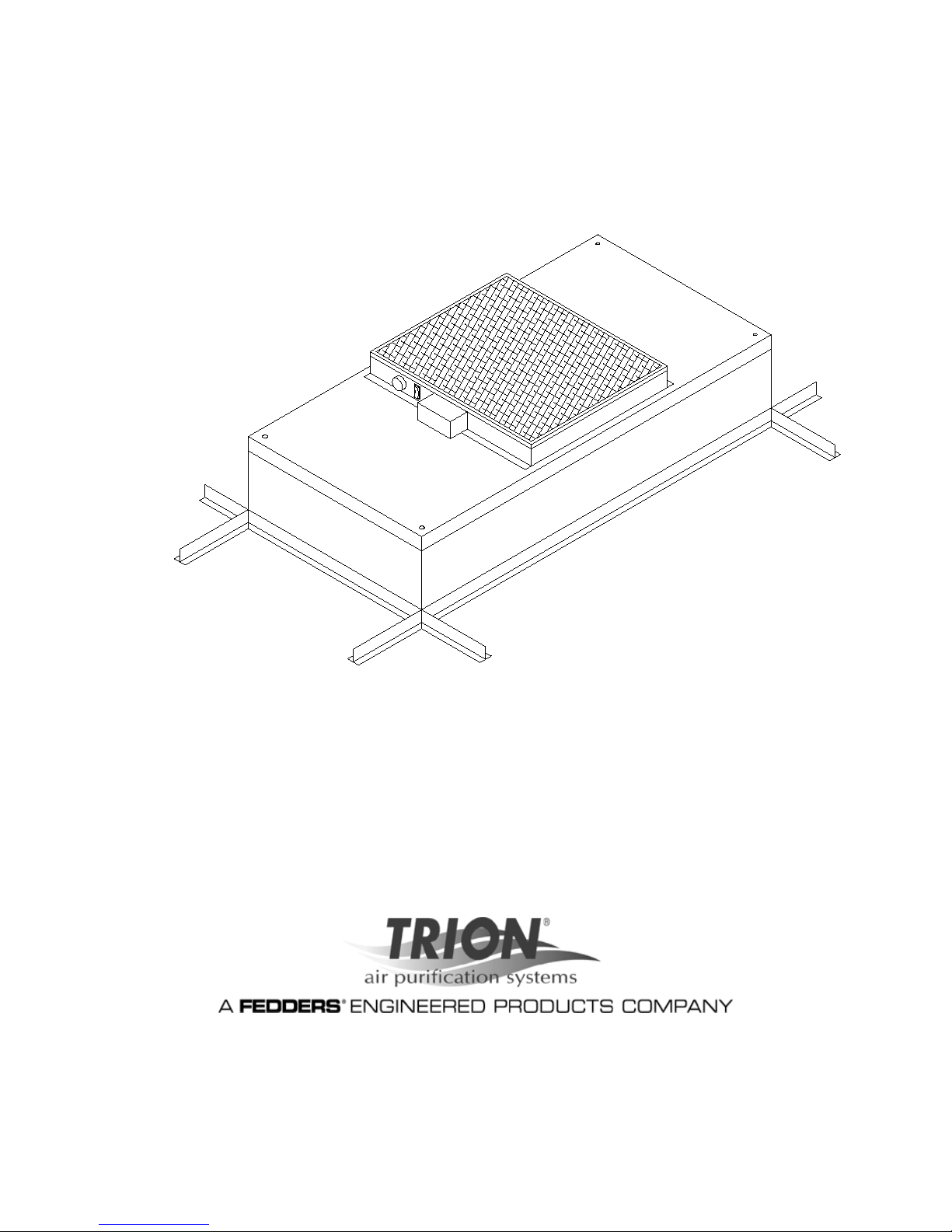
I. INSTALLATION
Note: The ELIMINATOR’s Filter Unit is completely assembled at the factory with the
exception of the prefilter, optional ¼” (0.64 cm)-20 eyebolts, and the “tee” bar gasketing
that are used when hanging the unit from an overhead structure.
Step 1A. Store units on 4’ side until ready to install, to prevent damage to the motor
vibration grommets.
Step 1B. Carefully remove the unit from the shipping carton and inspect for any
damage that may have occurred during transportation. (see Figure 1)
Figure 1
ELIMINATOR OWNER’S MANUAL
Page 2

Step 2A. Place the filter face side of the unit flat to the floor.
Step 2B. If optional eyebolts are ordered, screw the four eyebolts into the nutserts
on the lid assembly before lifting into an overhead position.
Step 3. Raise the unit and secure it into place using “S” hooks and chain to
suspend it from an overhead structure (supplied by others).
Step 4. Plug the unit into the appropriate voltage (115V, 277V A.C.) grounded
receptacle (if purchased with optional power cord) or hard wire according
to the wiring diagram (section VIII), page 10.
Step 5. Turn on the filter unit and let it run for a few hours before using in a clean
environment.
ELIMINATOR OWNER’S MANUAL
Page 3
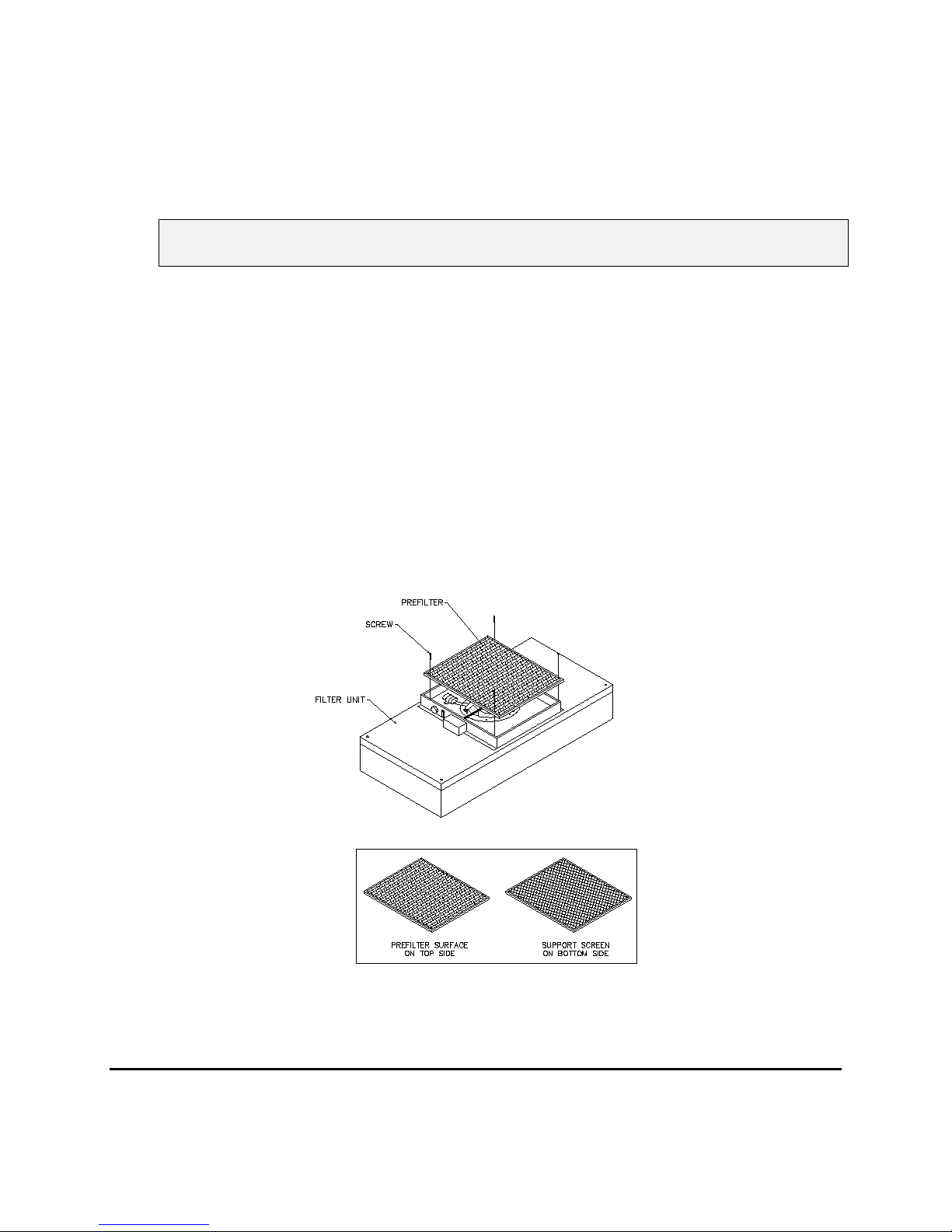
II. SERVICE: Cleaning the ELIMINATOR’s Prefilter
WARNING!
Disconnect the unit from the electrical power source before attempting any service.
Note: To keep the filter in top operating condition, washing the foam prefilter is
recommended every three to six months.
Step 1. To gain access to the prefilter, remove the ceiling panel next to the unit, if
applicable.
Step 2. Remove the four screws and lift the prefilter off the prefilter frame. (see Figure
2).
Step 3. Clean the prefilter by hand washing in water with a mild detergent of by using a
vacuum cleaner. Allow prefilter to dry completely before replacing.
Step 4. Reassemble by reversing the above steps.
Figure 2
ELIMINATOR OWNER’S MANUAL
Page 4

III. SERVICE: Removal and replacement of the HEPA filter.
WARNING!
Disconnect the unit from the electrical power source before attempting any service.
Step 1. To gain access to the HEPA filter, remove the ceiling panel next to the unit, if
applicable.
Step 2. Remove unit from ceiling.
Step 3. Remove the 10 screws holding the HEPA filter to the lid assembly.
Step 4. Lift the lid assembly off the HEPA filter and discard the HEPA filter (see Figure
4) as per requirements of the applicable regulations.
Note: Before replacing with a new HEPA filter, carefully inspect the new filter
for any visible damage.
Step 5. Also inspect the gasketing in the “tee” bar to insure a tight seal. Replace as
necessary.
Step 6. Replace with the new HEPA filter and assemble by reversing the above steps.
ELIMINATOR OWNER’S MANUAL
Page 5

IV. SERVICE: Removal and installation of the motor.
WARNING!
Disconnect the unit from the electrical power source before attempting any service.
WARNING!
Electrical service should be performed by licensed electricians or authorized Trion
service technicians.
Step 1. To gain access to the motor, remove the ceiling panel next to the unit, if
applicable.
Step 2. Remove the four screws and lift the prefilter off the prefilter frame.
Step 3. Remove the J-Box cover retaining screws and electric box cover and lift both
covers off. (See Figure 3)
Step 4. Make note of all wire locations for reinstallation later.
Step 5. Disconnect the two brown wires from the capacitor.
Step 6. Disconnect the motor wiring from the On/Off switch, ground and neutral and
release the conductor from the J-Box and electrical box.
Figure 3

ELIMINATOR OWNER’S MANUAL
Page 6
Step 7. Remove the six screws to free the venturi ring and the motor/blower assembly
from the lid assembly. (see Figure 6).
Step 8. Using a 5/32” (0.42 cm) Allen wrench, remove the blower wheel from the motor
shaft. Remove six #10 hex head bolts to remove the motor from the venturi ring.
Step 9. Replace with the new motor and reassemble by reversing the above steps. Set
the spacing between the venturi ring and the blower wheel at 0.06” (0.15 cm) clearance.
ELIMINATOR OWNER’S MANUAL
Page 7
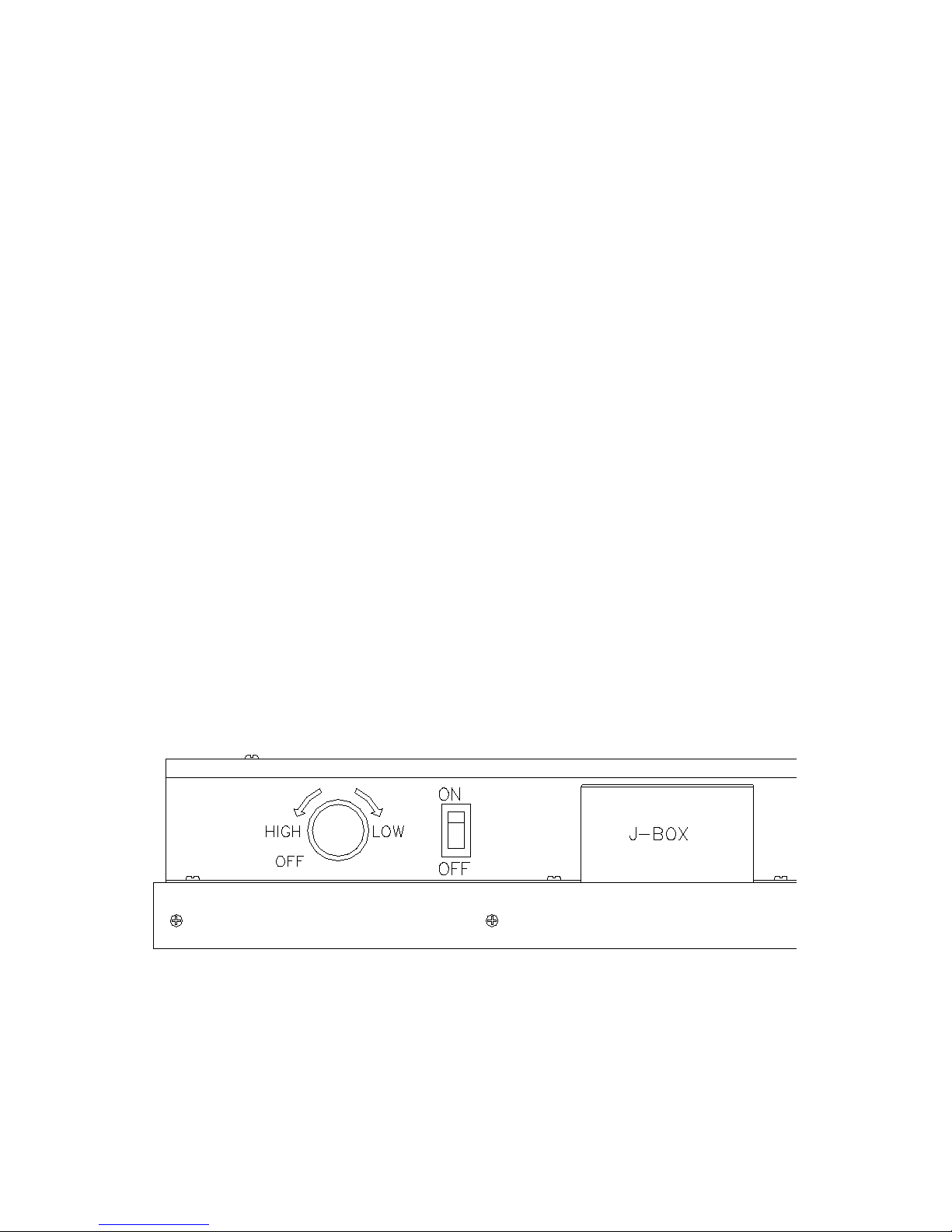
V. ON/OFF Switch/Speed Control – Speed/Airflow adjustment:
A. All Eliminator units are equipped with a two-position toggle switch, which is located on the
front side of the electrical junction box on top of the unit.
B. The top position is “OFF”. The bottom position is “ON”. (See Figure 4).
C. The speed control enables the adjustment of airflow at any setting within the recommended
performance range. The speed control knob is located on side of the prefilter bracket.
D. Electrical power to the fan may be disconnected by moving the toggle switch to the top or
“OFF” position.
E. Airflow/speed is adjusted by rotating the knob.
F. Clockwise →lowers the speed.
G. Counter-Clockwise →increases the speed.
H. Fully rotating the speed control knob to the left or counter-clockwise will turn the unit off.
Figure 4
Note: When turning the unit “ON” from the “OFF” position of the speed control, the fan is at
the highest speed. Turning the speed control knob clockwise will lower the speed.

WARNING!
Disconnect electrical power to the unit before attempting any electrical related service.
ELIMINATOR OWNER’S MANUAL
Page 8
VI. Trouble Shooting:
Low Air Velocity
Step 1. Check prefilter media; replace or clean as necessary.
Step 2. Adjust variable speed control for higher blower output.
Step 3. Check power supply for proper voltage, amperage and distribution frequency.
Step 4. Replace HEPA filter if the air velocity remains low.
High Air Velocity
Step 1. Adjust variable speed control for lower blower output.
Non-Laminar Flow and/or Excessive Contamination
Step 1. Insure that no large obstructions are upstream of airflow pattern.
Step 2. Determine that no other air-moving devices are operating in or around clean
room which disrupt room’s airflow pattern.
Step 3. Check air velocity and if low, conduct the “Low Air Velocity” procedure
outlined above.
Step 4. Conduct smoke and photometer test on HEPA filter. Seal or replace HEPA filter
as necessary.
ELIMINATOR OWNER’S MANUAL
Page 9
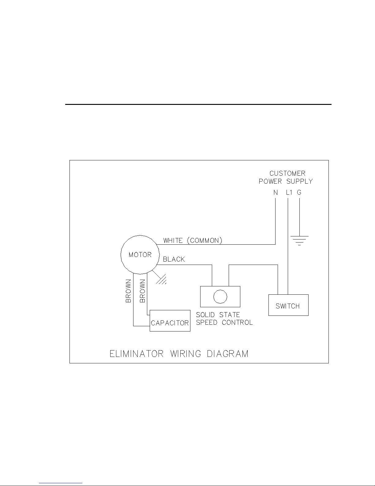
VII. ELIMINATOR Wiring Diagrams
Figure 5

ELIMINATOR OWNER’S MANUAL
Page 10
IIX. ELIMINATOR Replacement Parts List:
Description Quantity Trion part number
Per unit 115V 277V
______________________________________________________________________________
Prefilter 1 62981 62981
Motor 1 63755-001 63755-002
Capacitor 1 60078 61485
ON/OFF Switch 1 63518 63518
Speed Control 1 63011 63016
HEPA filter, 2 x 4 1 69406 69406
Optional Accessories:
Power Cord
10” (25.40 cm) or 12” (30.48 cm) diameter A/C intake collar
ULPA filter
Replacement parts are available through your authorized Trion representative. If you cannot
locate a representative in your area, contact Customer Service at:
TRION, Inc.
101 McNeill Road
Sanford, North Carolina 27330, U.S.A.
Tel: (919) 775-2201
(800) 884-0002
Fax: (919) 777-6399
Email: [email protected]
Web site: trioninc.com
ELIMINATOR OWNER’S MANUAL
Page 11
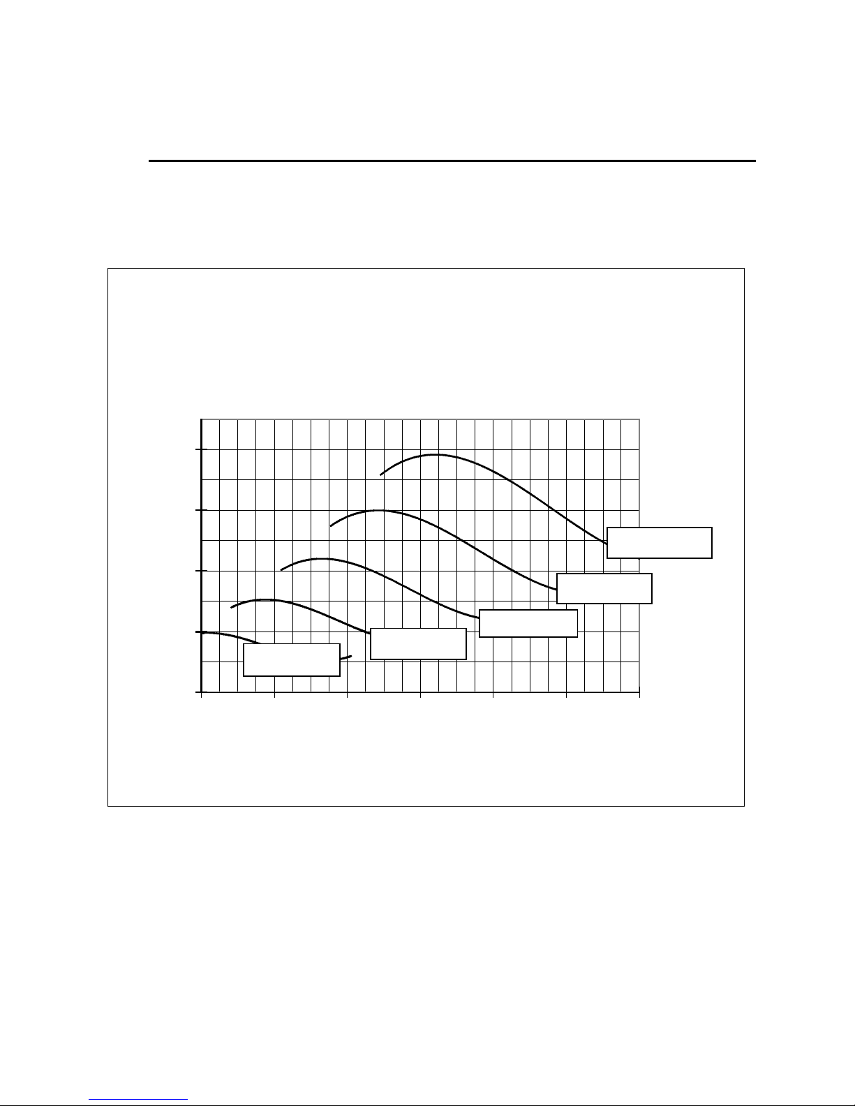
2X4 ELIMINATOR WITH
1/8 HP MOTOR
0.00
0.10
0.20
0.30
0.40
30 40 50 60 70 80 90
AIR FLOW (FPM)
STATIC PRESSURE (IN W.G.)
700 RPM
800 RPM
600 RPM
500 RPM
400 RPM

VIII. LIMITED WARRANTY
Trion, Inc. warrants the equipment will be free of defects in materials and workmanship under
normal use for a period of three (3) years. The HEPA filter shall only be warranted against
loading for a period of two (2) years when operated in clean room conditions. Trion’s sole
obligation under this warranty is to repair or replace any parts of the equipment which are
defective for a period of three (3) years from the invoice date, provided that the repair or
replacement is actually performed within the three (3) year period from the invoice date. The
buyer agrees to assume any incidental expenses including but not limited to the cost of
transporting the defective equipment to TRION’s repair facility. The buyer’s sole remedy under
this limited warranty is the repair or replacement of any defective part of the equipment. TRION
DISCLAIMS ANY IMPLIED WARRANTIES INCLUDING WARRANTIES OF
MERCHANTABILITY AND FITNESS FOR A PARTICULAR PURPOSE. In no event shall
TRION be liable for punitive, incidental, or consequential damages arising out of this sale,
including but not limited to damage to persons or property, loss of use, loss of time,
inconvenience, equipment rental, loss of earnings or profit or any other commercial loss. This
warranty excludes certain expendable items such as light tubes, prefilters, etc. TRION expressly
disclaims and excludes from this warranty any responsibility for equipment failures and/or
defects attributable to improper maintenance, abuse, accident or modifications of the equipment
(such as application of an adjustable frequency drive).
ELIMINATOR OWNER’S MANUAL
Page 12

IX. TESTING
Each ELIMINATOR filter unit is thoroughly tested at the factory before shipment.
However, because of the “rigors” of shipping, TRION encourages its re-test after
installation.
TRION recommends that the customer contact an independent organization, with
technicians trained and experienced in performance evaluation and maintenance of clean
air equipment.
Some of the testing procedures performed on the ELIMINATOR include aerosol
challenge of HEPA filters to assure specified performance, along with air velocity
measurement and adjustment tests.
For more information on testing procedures, contact:
Trion, Inc.
101 McNeill Road
Sanford, North Carolina 27330, U.S.A.
Tel: (919) 775-2201
(800) 884-0002
Fax: (919) 777-6399
Email: [email protected]
Web site: trioninc.com
ELIMINATOR OWNER’S MANUAL
Page 13
Table of contents
Popular Water Filtration System manuals by other brands


Deltec
Deltec FR 509 Operating instructions and spare parts lists

Clean Water Systems
Clean Water Systems PRO-OX 7000-SXT Installation & start?up guide

Oase
Oase Bitron C operating instructions

Evolution Aqua
Evolution Aqua eazypod Installation and instruction manual

Keating Of Chicago
Keating Of Chicago Safe and Easy Filter owner's guide

Aquatek
Aquatek ATUN Series Operation & maintenance manual