bluMartin freeAir100 Assembly instructions
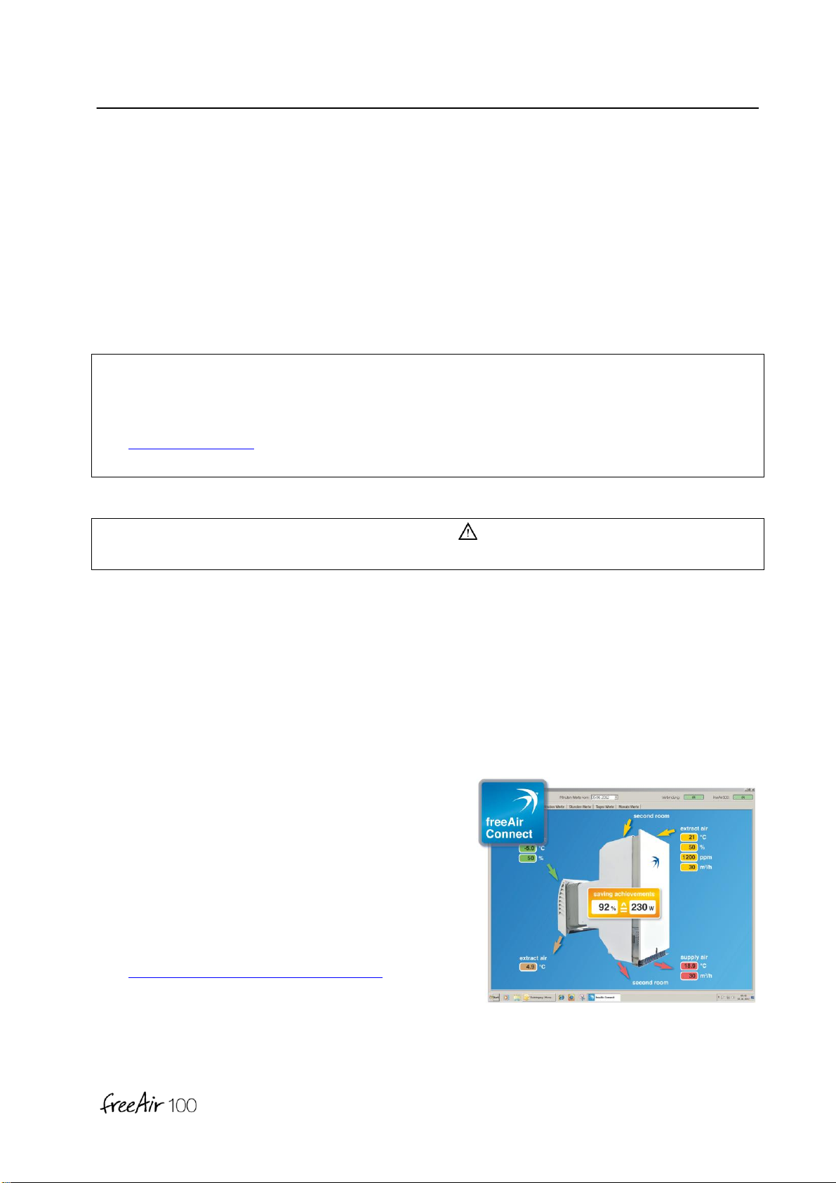
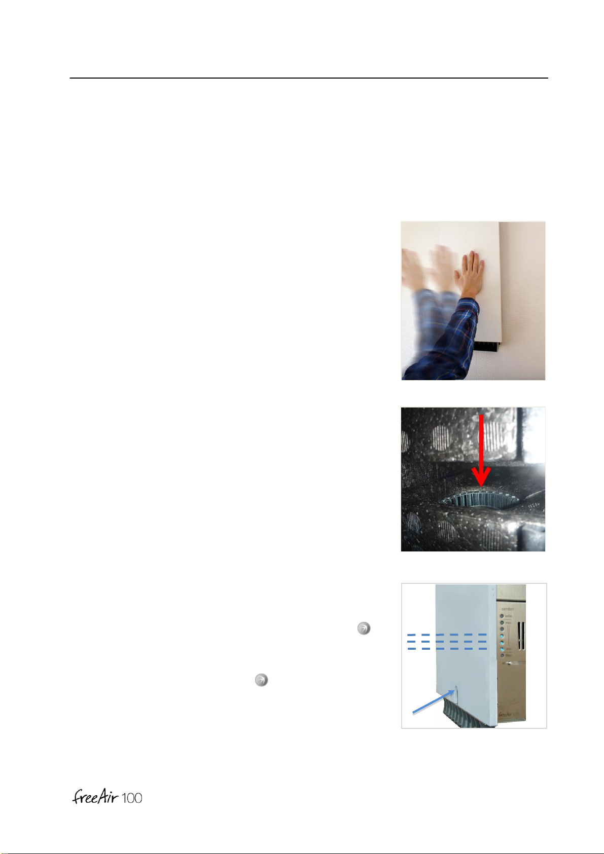
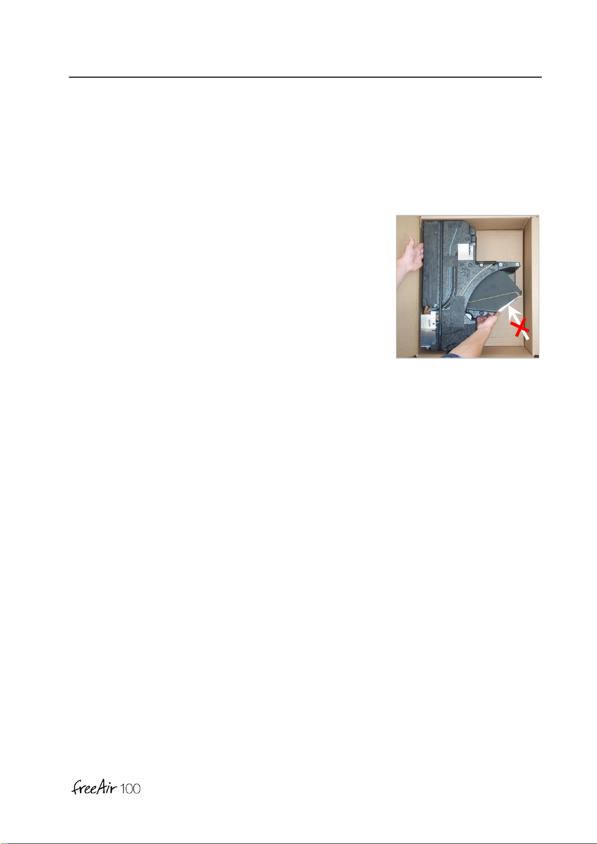
Service
[ S ] 32
Service
Notes
•The annual filter change does not require any tools.
•Original bluMartin replacement filters are available from the installer, from us
(info@bluMartin.de) or from Amazon.
•You need a Torx-10- and a Torx-20 screw driver for installation and service tasks.
DANGER
Observe all references to safety and use of the freeAir100 in part General [G].
Device Test
After correct installation turn the freeAir100 on and wait a few minutes while the device
executes a test routine.
Test Turbo operation once either only blue LEDs or no LEDs are illuminated.
Connect Software
For control of device functions and for any update,
we recommend:
•Laptop (Windows 7 or 8)
•USB cable (A on B)
•Our free software freeAir-Connect
and free updates for freeAir100
(www.bluMartin.de/service/downloads).

Service
[ S ] 33
Change of filter (annually or if required)
1. Pull your freeAir100 gently with both hands at the same
time left and right at the center of the panel from the wall
box and set it onto the flour.
Note
When removing the freeAir100 from the wall box it is
possible that some remaining condensate water will flow
from the heat exchanger.
2. Push the two metal flaps apart and remove the dirty
supply filter.
Please only use original bluMartin-filters.
Note
For allergy sufferers are also filter class F7 available
(increased air resistance some more noise).
3. Pull the extract filter out of the side of the device and
replace with original bluMartin-filter.

Service
[ S ] 34
Piep
4. Clean the wall box with soapy water. Also remove any
glue, plaster or paint residue, so the freeAir100 will slide
easily back into the wall box.
Before replacing the unit use the (included with the filter)
silicone lubricant and apply a thin film to the seal at the
leading edge of the wall box and at the gasket.
5. Support the appliance with your right hand in front and
bottom and slide it straight into the box. Slide by pressing
the front panel on the unit until it stops.
Note
The device will only be operational if seated completely
inside the wall box (if necessary beat with your hand on
the front panel).
6. To reset the filter hour counter shortly change into Service
mode. To do that turn first the device off.
Push and hold the -button and switch the device on
again.
Keep the -button pushed until you hear a short beep.
After that switch the device off once more, wait till all LEDs
have gone dark and switch the device on again.

Service
[ S ] 35
DIP Switches
1st Room Extract (m3/h)
In case of 2nd Room Extract option (= 4th flap) this will allow
the user to deactivate the hourly switch of extract air from 2nd
to1st room.
This makes sense in case your freeAir100 is installed inside
e.g. a closet.
Note
The deactivation is possible only when the 2nd Room Extract
is adjusted to 100 m³/h.
This feature is only available in devices with a serial number
of 3000 or higher.
2nd Room Extract (m3/h)
The additional 2nd Room Extract module enables adjustment of max air flow of ventilation for
exhaust of the 2nd room. Diameter, length and number of turns in the ducting as well as air inlet
size limit the air stream (see table above):
•off: No exhaust ducting installed or extract opening blocked
•30: One flex-duct connected (with extract valve 125)
•60: Two flex-ducts installed (with extract valve 125 and completely open)
• 100: Three flex-ducts or spiral-seam pipe DN100 installed (with extract valve 200)
Note
Incorrect adjustment or high air friction coefficient will lead to higher noise level and premature
filter error warning.

Service
[ S ] 36
Summer Cooling (°C)
A special feature of your freeAir100 is the active summer cooling. In the warm season the
device automatically activates a bypass in order to (mostly at night) cool down rooms with fresh
outside air. The amount of air will be increased, if necessary.
Select your desired temperature for the supply air room.
Note
This feature is only available in devices with a serial number of 2000 or higher.
Temperature is set to 22°C in older devices.
Room Area (m2)
Enter here the number of square meters to be ventilated. Please factor in all connected rooms.
This input is the basis for minimum ventilation calculations.
Notes
•If you find the intermittent operation bothersome adjust the room area
to less than 60 m2at Comfort Level 1
or to less than 35 m2at Comfort Level 3.
•Adjust the Room Area to 60 or 75 m2to guaranty a level of minimum ventilation of 20 m3/h
for humidity control according to DIN 1946-6.

Service
[ S ] 37
Front Plate Installation
1. Paint the front plate with the color of your choice (interior
paint or lacquer).
2. Carefully slide the front plate onto the device (don’t
damage cables). Attach the included M3 screws for
grounding of the front panel. Then attach the front plate
with 4 counter sunk (4 x 20) wood screws.
Note
Please make sure to adjust the DIP-switches first (see
above in this section).
DANGER
A missing grounding screw in the front plate can cause injury or death by electrical shock.

Service
[ S ] 38
Air Outlet Installation
1. Slide the air outlet into the device. Press the EPP foam
body with a finger a little bit down.
2. Attach the metal sheet using two M3 raised head screws.
Notes
The supply air outlet is designed to guide air into the room
as far as possible.
Air direction can be changed by adjusting the air paddles.
Air outlets guiding air downward are available as an extra.
Filter Installation
Attach the metal bracket for the inlet air filter using four
4x20 flat head screws.

Service
[ S ] 39
Piep
Service –Operation
To change to the service operation switch off the device using the
main power switch.
Push and hold the -button and turn the device back on at the
main power switch. Keep holding the -Button until a short
beep is audible.
LEDs will blink in Service Mode.
Instead if the Comfort Level, alternative air flow can be selected
to 20, 30, 40, 50, 60, 70, 80 or 100 m3/h by using the -Button.
Notes
•Selecting the Service Operation will reset the filter hour counter to zero.
•After switching the device off and back on all functions will be restored to Comfort or
Dehumitification operation.
•Prolonged holding of the -Button will launch Test Operation (the upper middle as well as
the lower blue LEDs will be on).
•In Service Operation some functions such as defrost are not available. Therefore this
operation should only be used during maintenance work.
While switching the device on –none illuminated LEDs indicate
the firm ware version digitally from the bottom up.
Here is an example for version 1.10.
16
8
4
2
1
8
+
2
= 10

Service
[ S ] 40
Error Messages
Filter Run Time
Indicates that it has been more than 8.000 operational hours (or
roughly one year) since the last filter change.
Note
After filter has been replaced select Service Operation to reset
the hour counter.
Filter Contamination
One or both fans indicate an error because the air flow is
restricted due to a dirty filter.
This error message can also be triggered by other air flow
obstructions such as (under dimensioned opening between
supply and extract air, DIP-switch setting for extract air is set too
high or simultaneous operation of a kitchen vent hood while
windows are closed).
CO2Content
CO2-content is measured to be above 3500 ppm.
An acoustic warning will sound for 30 seconds.
Piiep
Piiep
Piiep

Service
[ S ] 41
Fire Alarm
A temperature sensor indicates a temperature of above 80°C.
The device will power down and close air flaps.
Control Error
The device will power down and close air flaps.
Red LED is illuminated –yellow LED will flash:
By pushing the -Button the following described error causes
are indicated.
Note
Error messages will be erased by switching the device off and back on at the main power
switch.
Piep
Piep
Piep
Piep
Piep
Piep

Service
[ S ] 42
Control Error Analysis
1. Control-Error will be indicated.
2. Push and hold -Button.
3. Cause of error display:
CO2 Sensor Temperature Sensor Outside Air Temperature Sensor Exhaust
______________________
__ __ __ __ __ __
______________________
__ __ __ __ __ __
______________________
__ __ __ __ __ __

Service
[ S ] 43
Temp. Sensor Extract Air Temp. Sensor Supply Air Humid Sensor Outside Air
Humidity Sensor Extract Air Pressure Sensor Fan Extract Air
>> See error correction
Fan Supply Air Extract Flap 2nd Room Extract Flap
>> See error correction
__ __ __ __ __ __
______________________
__ __ __ __ __ __
______________________
__ __ __ __ __ __
______________________
______________________
__ __ __ __ __ __
______________________
__ __ __ __ __ __
__ __ __ __ __ __
______________________
__ __ __ __ __ __
______________________
__ __ __ __ __ __
______________________
__ __ __ __ __ __
__ __ __ __ __ __
______________________
__ __ __ __ __ __

Service
[ S ] 44
Supply Air Flap Bypass Flap DIP Switch
>> See error correction
4. Notify your service partner in case an error can't be cleared.
Indicate error cause as well as the freeAir100 serial number.
Note
Returning the device has to be coordinated with your service partner. The device has to be
shipped using the appropriate packaging.
__ __ __ __ __ __
______________________
__ __ __ __ __ __
__ __ __ __ __ __
______________________
__ __ __ __ __ __
__ __ __ __ __ __
______________________
__ __ __ __ __ __

Service
[ S ] 45
Error Correction
Device can't be switched on
The freeAir must be installed flush with the wall box. Clean the
wall box and tap the front plate of the device to assure a tight fit.
In case the device still does not turn on wait several minutes
before switching the device back on.
Fan does not move (knocking sound every 30 seconds)
Fan is jammed due to improper transportation.
Remove the extract filter and carefully push the blade wheel
downward.
For the supply air fan –loosen the 4 outer flat head screws and
lift up the motor plate by 10mm.
Blue LEDs blinking (continuously)
Service- or Dehumidifying operation is active.
Service operation is activated by pushing and holding the -
Button while the device is switched on. This can happen by
accident or because of a mechanical jamming.
Uninstall the front cover and free the -Button.
Leave Service operation by switching the device off and back
on.

Service
[ S ] 46
DIP Switches
Check to see whether a 2nd Room Extract connection had been
selected even though the device is not equipped with one (no 4th
air flap and seal present).
Also check to see whether 1st room extract is deselected even
though the 2nd Room Extract is not set to 100 m³/h?

Service
[ S ] 47
Packaging
To extract the device from the packaging use your right hand to
reach under the EPP-Foam body.
Note
Take care not to reach into the fragile fins of the heat
exchanger.
Transport and Storage
Components of the freeAir100 must only be transported in the correct packaging. The
freeAir100 must be shipped on a pallet to protect it from shock. The freeAir100 and packaging
must be protected from moisture.

Service
[ S ] 48
Commissioning
Date: Serial number:
Company: Phone number: Signature:
Annual Filter Change Service Log
Date: Signature:
Date: Signature:
Date: Signature:
Date: Signature:
Date: Signature:
Date: Signature:
Date: Signature:
Date: Signature:
Date: Signature:
Date: Signature:
Date: Signature:
Date: Signature:
Date: Signature:
Date: Signature:
Date: Signature:
Date: Signature:
Note: Filter Run Time counter has to be reset

Service
[ S ] 49
Date: Signature:
Date: Signature:
Date: Signature:
Date: Signature:
Date: Signature:
Date: Signature:
Date: Signature:
Date: Signature:
Date: Signature:
Date: Signature:
Date: Signature:
Date: Signature:
Date: Signature:
Date: Signature:
Date: Signature:
Date: Signature:
Date: Signature:
Date: Signature:
Date: Signature:
Date: Signature:
Date: Signature:
Note: Filter Run Time counter has to be reset
Table of contents