Hi-Link HLK-LD012-5G User manual

Shenzhen Hi-Link Electronic Co., Ltd.
HLK-LD012-5G Radar Module
User Manual
Version: V1.1 Date: 3rd, Aug.2020 All rights reserved © Shenzhen Hi-Link Electronic Co.Ltd

Contents
1. Brief Introduction.................................................................................................................................................1
2. Module Picture...................................................................................................................................................... 1
3. Module size and pin position........................................................................................................................2
4. Electrical parameters......................................................................................................................................... 3
5. Sensing time and sensing distance adjustment.................................................................................. 3
6. Photosensitive detection.................................................................................................................................. 4
7. Module power-on sequence diagram.......................................................................................................5
8. Schematic diagram of detection range....................................................................................................5
9. Precautions...............................................................................................................................................................6
10. Revision History................................................................................................................................................7
User Manual
Page 1/ 7
HLK-LD012-5G
1. Brief Introduction
HLK-LD012-5G is an ultra-low power 5.8G radar sensor launched by Hilink Electronics, with an
overall power consumption of about 68uA.
The module size is 20mm*20mm. The module fully integrates 5.8GHz microwave circuit,
intermediate frequency amplifier circuit and signal processor.
It has high integration and good production consistency. The peripheral is equipped with a small
planar antenna to ensure the performance of the sensor while greatly reducing total measurement.
The sensor can be used to detect the presence of human body or various scenes of moving target
sensing, including smart home, Internet of Things, and smart lighting.
It is especially suitable for low-power battery-powered scenes such as night lights, solar street
lights, and wireless cameras.
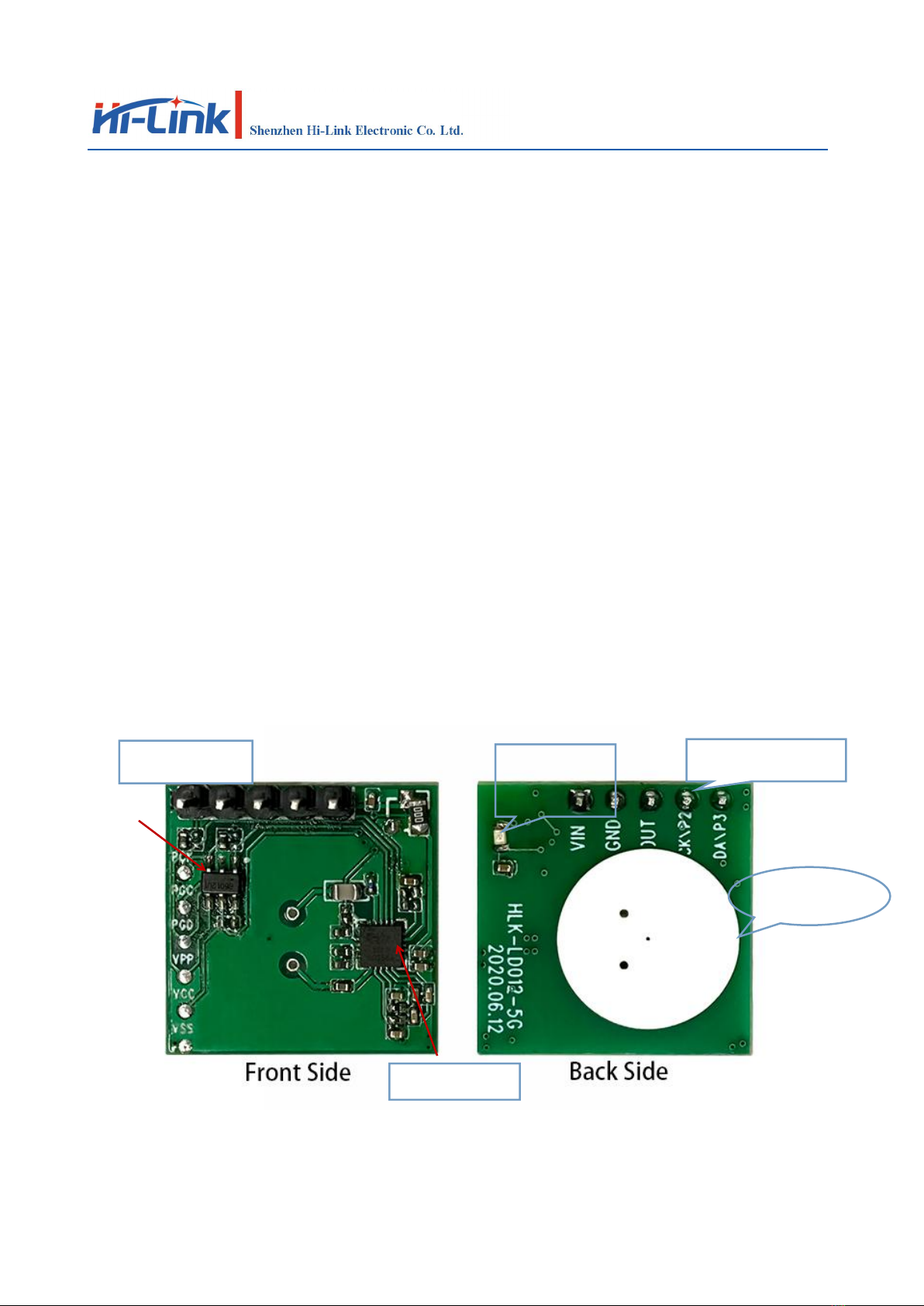
2. Module Picture
HLK-LD012-5G Radar Module physical picture
In/Out Connector
Photodiode
Flat antenna
External MCU
Radar Chip

User Manual
Page 2/ 7
HLK-LD012-5G
The module reserves 5 pin holes, with a total of five signal PINs VCC, GND, OUT, P2 and P3.
The PIN distance is 2.54mm. If you need to tune the distance and delay time and other parameters,
you can hang or pull down P2 and P3.
The state matches the specific resistance on the module to select the corresponding gear or use the
external MCU reserved on the module to rewrite the internal parameters. The following table shows
the definition of each PIN:
Pin
Funtion
Remark
VIN
Module power
supply
LDO is not attached by default. Lithium battery or dry battery
can be used for direct power supply (2.7~4.8V). If the power
supply voltage exceeds 5V, LDO needs to be added. At this
time, the power supply VCC is 5~12V
GND
GroundedPIN
OUT
Output Signal
Output signal is high and low level(0V/2.2V)
P2
GPIO2
Receiving gain gear selection
P3
GPIO3
Delay time gear selection
3. Module size and pin position
The figure below is a schematic diagram of the size and pin position of the module.
The length and width of the module are 20mm*20mm, and the factory default does not have pins
The overall thickness is 2.5mm, if you need to bring pins, the default pin height is 12mm.
User Manual
Page 3/ 7
HLK-LD012-5G
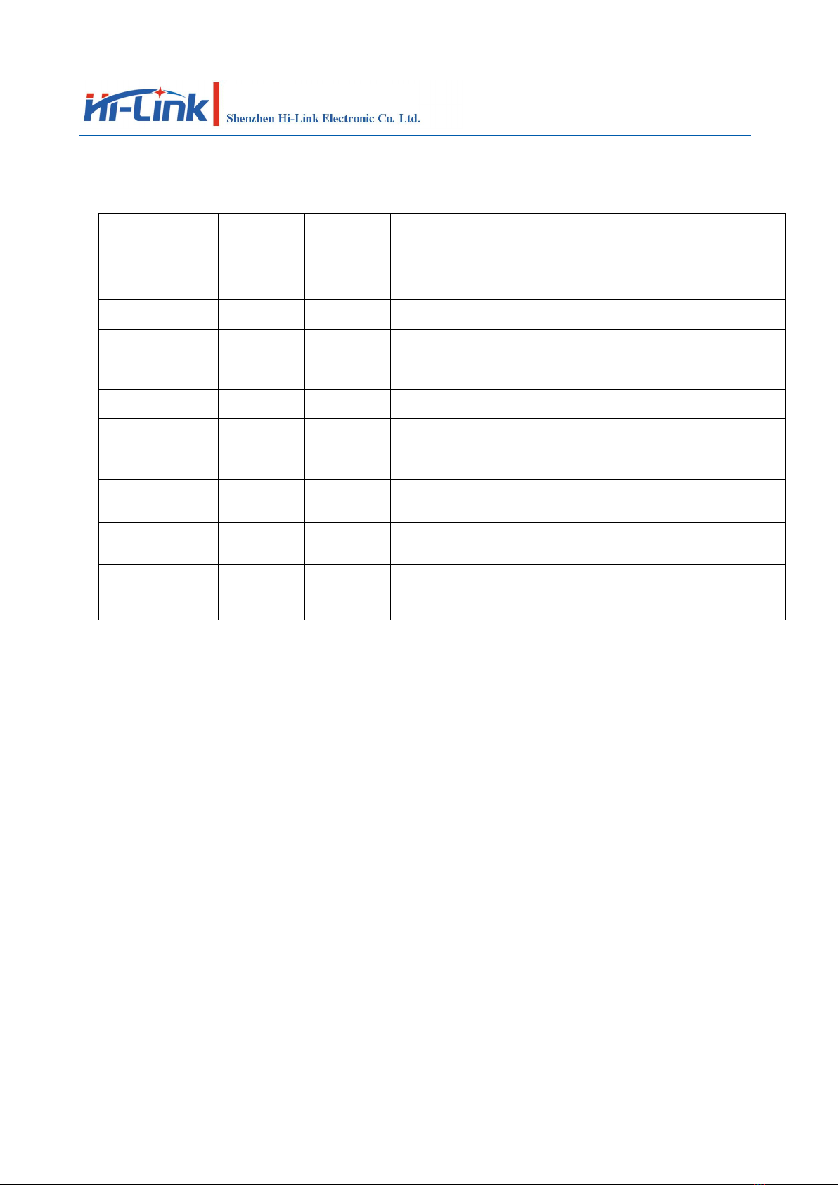
4. Electrical parameters
Parameters
Minimum
Value
Typical
Value
Maximum
Value
Unit
Remarks
Transmit frequency
5725
5875
MHz
Transmit power
0.2
0.5
mW
Input voltage
2.7
3.3
4.8
V
LDO is not attached by default
Output high level
2.2
V
Output low level
0
V
Working current
68
75
uA
Average working current
Hanging height
8
10
M
Forward sensing distance
Sensing radius
15
S
Adjustable according to specific
needs
Delay time
10
Lux
Adjustable according to specific
needs
Photosensitive
threshold
-30
85
°C
5. Sensing time and sensing distance adjustment
The P2 and P3 pins on the HLK-LD012-5G module are used to select different sensing distances
and delay gears; P2 is used to adjust the sensing distance, which can be provided with the 3
resistors (th0, th1, th2) reserved on the module 16 different sensing distance options.
When P2 is suspended or pulled up, the sensing distance of the module is far; when P2 is pulled
down, the receiving gain is reduced by 18dB and the sensing distance is short. The three distance
adjustment resistors on the module are used to adjust the threshold of the inductive judgment. The
resistance bit NC represents 1, and the 0 ohm resistor represents 0. Refer to Figure 4 for the status
of the 3 resistance bits and the corresponding threshold. The smaller the threshold, the farther the
sensing distance.
P3 is used to select the pull-up time of the OUT signal after sensing. When P3 is floating or pulled

User Manual
Page 4/ 7
HLK-LD012-5G
high, the sensing pull-up time is 2 seconds; when P3 is pulled low, the sensing pull-up time is 15
seconds. If there is a new trigger during the inductive output pull-up period, the inductive time will
be extended.
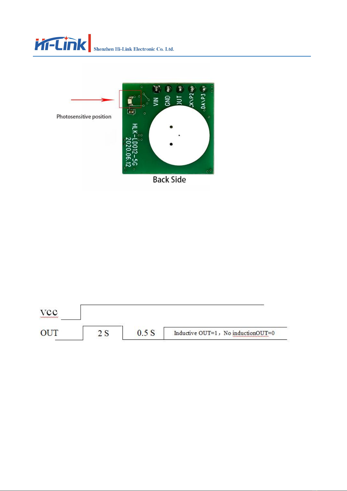
6. Photosensitive detection
The module supports photosensitive detection. The sample module does not enable the
photosensitive detection function by default.
The position shown in Figure 5 is a photosensitive diode. The photosensitive threshold can be
adjusted by changing the photosensitive judgment threshold or tuning the photosensitive resistance.
In the version with photosensitive function, the radar sensor will be activated only when the
ambient light is lower than the set illuminance.
If the light is too bright, the module will not activate the sensor function. (After the photodiode is
mounted in a bright environment, the current consumption of the module will increase by about
5uA)
User Manual
Page 5/ 7
HLK-LD012-5G
7. Module power-on sequence diagram
The module has a power-on self-check function, that is, after the module is powered on, the OUT
pin first outputs a high level, and then outputs a low level after a delay of 2S, and enters the normal
induction mode after a delay of 0.5S.
The following is the control signal after the module is powered on Timing diagram:
8. Schematic diagram of detection range
The sensing sensitivity of the radar sensor can be configured by adjusting the resistance, and its
positive limit sensing distance is 10 meters, and the actual sensing distance can be adjusted
appropriately as needed.
The following schematic diagram of the radar detection range of the typical scene. If the

User Manual
Page 6/ 7
HLK-LD012-5G
sensitivity is set higher, the detection range will be correspondingly larger.
The dark area in the figure is the high sensitivity area, which can be fully detected in the area,
and the light color area is the low sensitivity detection area. , Objects can be basically detected in
this area.
HLK-LD012-5G lateral sensing range diagram (unit m)
9. Precautions
1. When installing the antenna, avoid metal shells or components on the front of the antenna to
avoid shielding the signal. Plastic or glass is allowed, but the obstruction should not be close to the
front of the antenna;
2. Try to avoid directing the radar antenna to large metal equipment or pipelines;
3. When installing multiple radar modules, try to ensure that the antennas of each radar module are
parallel to each other, avoid direct illumination between the antennas, and keep a distance of more
than 1m between the modules;
4. The radar sensor should avoid facing the AC drive power supply and try to stay away from the
rectifier bridge of the drive power supply to avoid power frequency interference with radar signals;

User Manual
Page 7/ 7
HLK-LD012-5G
10. Revision History
Revision
Release Date
Description
1.0
2020/07/08
Initial version
1.1
2020/08/03
Update electrical parameters
Table of contents


