Hi-Tec Sky Scout User manual

Instruction Manual
Ver 1.0

2
Fly high with Hitec
{GGjG
Thank you for purchasing Hitec’s Sky Scout.
'eYeOopeGanGengineereGEy 0uOtipOe[ PanufactureGEy Hitecthe Sky Scout is an iGeaOPoGeOfor aOO users interesteGin PoGeOÀyingregarGOess of
age or genGer. The Sky Scout is easy to ÀyeYen for Eeginners. This instruction PanuaOincOuGes the PoGeOspeci¿cationssafety precautions anG
assembly instructions for the KIT version of the Sky Scout. Please be sure to read this manual in its entirety before beginning the assembly and
operation of your Sky Scout Model Kit.
Warning : Be sure to read this section for your own safety.
Caution : Be sure to read this section to prevent accidents and damage to your model.
Tip : This section will help you maximize the performance of your model.
Note : This section will provide more detailed explanations.
The Sky Scout is a radio control model plane designed for users over age 14. For those under age 14, please seek the help of your parents,
guardian or the help of a skilled RC pilot. Improper assembly or user negligence can lead to serious injury and/or property damage to
yourself or other persons. Hitec is not responsible for any damages or injuries caused by the user’s negligence or improper assembly of the
model. %e sure to read the instruction manual thoroughly before assembly and Àying.
The Sky Scout is manufactured of ELAPOR, a material highly suited for model airplanes. ELAPOR is light, durable and unlike traditional
foams it can be bonded successfully with traditional cyanoacrylate adhesives and activators. Do not use foam-safe or “odorless” CA, epoxy
or other household glues. It is recommended that you wear safety goggles when using CA glue and be sure to follow the manufacturer’s
safety instructions for its use.
6SHFL¿FDWLRQV
:LQJVSDQPPLQ
2YHUDOOOHQJWKPPLQ
0LQDOOXSZHLJKWVWDQGDUGJR]
:LQJDUHDDSSUR[GPVTLQZLQJWDLOSODQH
H[FOIXVHODJH
0LQZLQJORDGLQJJGPR]VTIW
5&IXQFWLRQVUXGGHUHOHYDWRUDQGWKURWWOHRSWLRQDODLOHURQV
zGvaGpGMGzG
Section One: Introduction
Introduction & Specifications
Recommended Equipment
Other Sky Scout Versions
Safety Precautions
Section Two: Model Assembly
Cautionary Notes
Tools and Supplies Needed for Assembly
Parts Layout and Listing
Assembly Instructions
Section Three: Preparing Your Model for Flight
Section Four: Flying Your Model
Pre-Flight Inspections
Taking Off
Controlling the Plane
Landing the Plane
Section Five: Maintaining Your Model
Replacement Parts and Components
Customer Service Information
Appendix A: The Basics of Model Flying
Appendix B: Transmitter Control Surface Movements
2
3
3
4
5
5
6
8
15
16
17
17
17
18
20
21
23

3
Fly high with Hitec
zGvaGyGlGOGP
The KIT version of the Sky Scout only includes the airframe, associated hardware, along with the prop and spinner assembly. The following additional
parts and eTuipment are needed to complete the assembly. 9isit a Radio Control Hobby shop or consult an experienced Àier about purchasing the right
equipment for your needs.
&KDQQHO$LUFUDIW5DGLR
The Sky Scout requires at least a -channel radio to Ày. Adding the
optional ailerons requires a 4th channel, though a 5 or higher channel
radio with mixing features will allow for additional Àight performance.
We recommend Hitec models such as the Optic 5 or Optic 6 Sport for
optimal operational performance
5HFHLYHU
We recommend at least a 5 channel aircraft receiver that matches your
radio system for maximum Àexibility. Models such as the Hitec Minima
6T or 6S will ¿t this need if you are using a Hitec brand .4 *H]Radio.
6HUYRV
You will need at least two Sub Micro servos to complete your model. If
you choose to add the optional ailerons you will need an additional two
sub-micro servos. Hitec recommends using the HS-55 or HS-555M*
on all surfaces. These servos are available at most Radio Control
Hobby stores.
0RWRU
You will need a brushless outrunner motor designed for aircraft use.
We recommend the minimum of a -watt 11Kv motor. The motor
dimensions need to be no more than mm in diameter and mm in
length. To avoid having to use a special adapter make sure the output
shaft is either or .mm in diameter. The Sky Scout Kit contains Prop
adapters in both of these si]es.
(6&
You will also need an Electronic Speed Control with built in BEC that is
suitable for the motor you purchased. Hitec recommends using an ESC
with a minimum rating of an 1A and a BEC output of at least 1.5 amps
%DWWHU\&KDUJHU
For optimal performance Hitec recommends a 3-cell 11.1V 1300mAh
LiPo battery with at least a 15C discharge rating. You will also need a
charger capable of charging this battery as well. tions you are using.
3-4 CH AIR TX
1
RECEIVER
2
SERVOS
3
zGvaGvGzGzG}G
Radio, Receiver and Power Set Components for Each Version
(READY TO GO) stock# 13207
This version includes everything you need to Ày your Sky Scout after a few easy assembly steps.
Semi-assembled model
Semi-assembled model
Hitec Lite 4 .4*H]4-channel Radio w/4AA aIkaline batteries
Hitec Minima 6S Receiver installed
Hitec HS-55 Servos installed
(HITEC TO GO) stock# 13209
This version allows you to Ày your Sky Scout with the Hitec radio you already have or may wish to purchase. Any of Hitec’s
AFHSS .4*H]radios, or radios using a Spectra .4*H]module, can be linked with the Minima 6S included in the H*O set.
Semi-assembled model
Hitec Minima 6S Receiver installed
Hitec HS-55 Servos installed
C1-1100 Brushless Outrunner Motor installed
(PLUG-IN TO GO) stock# 13210
This Sky Scout version is for modelers who already own the additional products needed for Àying. A transmitter, receiver,
charger and suitable batteries are required needed to Ày the model plane.
Semi-assembled model
Hitec HS-55 Servos installed
C1-1100 Brushless Outrunner Motor installed
Hitec HBE-1A ESC installed
C1-1100 Brushless Outrunner Motor installed
Hitec HBE-1A ESC installed
HLP-3S 1300mah Li-Po battery included
C*-115 DC Balancing Charger included
Hitec HBE-1A ESC installed
HLP-3S 1300mah Li-Po battery included
C*-115 DC Balancing Charger included
CHARGER
6
BATTERY &
ESC
5
MOTOR
4

4
Fly high with Hitec
zGvaGzGwG
The product contains small
and sharp components.
Please be sure to keep
them away from children at
all times.
Be sure to connect the batteries
with the right polarity.
Disconnect the battery if it
is damaged or produces
excessive heat.
Be careful when using tools
like knives, scissors and
screwdrivers.
Keep away from rotaing
propellers to prevent injuries.
The motor and battery may
produce heat during the
pre-Àight test or during the
Àight. Be sure to cool them
off before touching them or
recharging the battery.
Do not Ày in strong
winds or storms.
The Sky Scout may
not perform
as desired.
Always disconnect the batteries
from the the model when its not in
use. Leaving the battery connected
may cause it to overheat may
damage the model.
Do not use or attempt to repair a
distorted or damaged spinner or
propeller blade. They may fail
under operation, risking injury
or property damage.
Do not store the Sky Scout
or accessories in humid,
closed areas, in high
temperatures or in direct
sunlight.
Be sure to use of¿cial Hitec products
and components. Altered products
may negatively affect the model’s
performance.
Link
Lithium-Polymer LiPo
batteries can pose
signi¿cant risk when
mishandled. Keep them
away from ¿re to prevent
explosion and unplug
immediately if they feel hot
or show signs of swelling.
Do not separate individual cells or stab the
battery with a sharp tool. The battery may
explode and cause injuries.
Only recharge your LiPo batteries with a
dedicated LiPo charger such as the
Hitec C*-115 DC Charger.
Do not attempt to recharge
with a charger designed for
NiCd or NiMH cells.
Link
V-TAIL
OFF
ELEVON
CH1CH2CH3CH4
REV
NOR
2.4GHz
4
Channel
Aircraft
Radio

5
Fly high with Hitec
&DXWLRQDU\1RWHVEHIRUH$VVHPEOLQJWKH6N\6FRXW
Keep in mind when assembling and Àying the Sky Scout that radio control model airplanes may cause injury or property damage when
improperly Àown or mishandled. Always follow the warnings written in the instruction manual. Improper usage could lead to damage
and / or failure of the electronic equipment. Be sure to read this instruction manual in its entirety before assembling and Àying this model.
$VVHPEO\,QVWUXFWLRQV
This section will help you prepare your Sky Scout for Àight as quickly as possible. Read and follow the following instructions carefully.
Experienced pilots may choose to install the optional ailerons for additional Àight performance. While the necessary hardware is included
with your Sky Scout, two additional sub-micro servos, such as the Hitec HS-55, and two servo extensions are required. The mechanical
installation of the servos and aileron controls are detailed in the assembly instructions on page , steps , and Page 11, steps 4
through .
zG{aGtGh
This instruction manual is for users who purchased the KIT version of the Sky Scout. It contains detailed instructions of how to quickly and easily
assemble your model airplane.
Razor Knife
Medium Strength Thread Locker
Gap Filling Cyanoacrylate Glue
(referred to as CA in the instructors)
Do not use “Foam Safe”CA
8se caution when using sharp tools like ra]or knives and wire cutters. Be sure to follow the manufacturer’s instructions and warnings
when using Cyanoacrylate adhesives. The necessary tools and adhesives can be purchased in your local RC hobby retailer.
Tools needed for assembly (sold separately)
Spray Activator
Wire Cutters

6
Fly high with Hitec
%HIRUH<RX6WDUW%XLOGLQJ
Verify you have all the contents of your kit using the image below
and the parts list on page 7. If any parts are missing contact
our customer service department for replacements.
zG{aGwGsGGsG

7
Fly high with Hitec
zG{aGwGsGGsG
3DUW1R 'HVFULSWLRQ 0DWHULDO 'LPHQVLRQV
6PDOO3DUWVVHW
3ODVWLFSDUWVVHW
:LUHURGVHWZLQJMRLQHU
3URSHOOHUGULYHUVSLQQHUVHW6N\6FRXW
$
%
%XLOGLQJLQVWUXFWLRQV.,7
&RPSODLQWVIRUPPRGHOV
'HFDOVKHHW$
'HFDOVKHHW%
/+IXVHODJHVKHOO
5+IXVHODJHVKHOOZLWK¿Q
&DQRS\
7DLOSODQH
/+ZLQJSDQHO
5+ZLQJSDQHO
/+MRLQHUFKDQQHOFRYHU
5+MRLQHUFKDQQHOFRYHU
/+VHUYRZHOOFRYHU
5+VHUYRZHOOFRYHU
9HOFURWDSHKRRN
9HOFURWDSHORRS
7ZLQFRQWUROVXUIDFHKRUQ
6ZLYHOEDUUHO
$OOHQKHDGJUXEVFUHZ
$OOHQNH\
3UHIRUPHGDLOHURQSXVKURG
/DWFKFDWFK
/DWFKWRQJXH
&DEOHKROGHU
6FUHZPRWRUFRZO
)LUHZDOO
0RWRUFRZO
&RZOVFUHZVXSSRUW
6HUYRPRXQWÄ1DQR³XSULJKW
7DLOSODQHFOLS
8SSHUWDLOSODQHVOHHYH
/RZHUWDLOSODQHVOHHYH
7DLOSODQHIUDPH
7DLOSODQHVOLGHU
3URSHOOHUERVV
6SLQQHU
)ROGLQJSURSHOOHUEODGH
3URSHOOHUGULYHUWDSHUFROOHW
:DVKHU
3DQKHDGVHOIWDSSLQJVFUHZ
2ULQJ
'RZHOSLQ
1XW
6KDNHSURRIZDVKHU
7DSHUFROOHW
:LQJMRLQHU
3UHIRUPHGSXVKURGHOHUXG
6QDNHLQQHUWXEHHOHUXG
6QDNHRXWHUVOHHYHHOHYDWRU
3ULQWHGVHOIDGKHVLYH¿OP
3ULQWHGVHOIDGKHVLYH¿OP
0RXOGHG(ODSRUIRDP
0RXOGHG(ODSRUIRDP
0RXOGHG(ODSRUIRDP
0RXOGHG(ODSRUIRDP
0RXOGHG(ODSRUIRDP
0RXOGHG(ODSRUIRDP
0RXOGHG(ODSRUIRDP
0RXOGHG(ODSRUIRDP
0RXOGHG(ODSRUIRDP
0RXOGHG(ODSRUIRDP
3ODVWLF
3ODVWLF
3ODVWLF
0HWDO
0HWDO
0HWDO
0HWDO
,QMPRXOGHGSODVWLF
,QMPRXOGHGSODVWLF
,QMPRXOGHGSODVWLF
0HWDO
,QMPRXOGHGSODVWLF
,QMPRXOGHGSODVWLF
,QMPRXOGHGSODVWLF
,QMPRXOGHGSODVWLF
,QMPRXOGHGSODVWLF
,QMPRXOGHGSODVWLF
,QMPRXOGHGSODVWLF
,QMPRXOGHGSODVWLF
,QMPRXOGHGSODVWLF
*53WXEH
0HWDO
3ODVWLF
3ODVWLF
3ODVWLF
3ODVWLF
3ODVWLF
0HWDO
0HWDO
0HWDO
3ODVWLF
0HWDO
0HWDO
6SULQJVWHHO
0HWDO
[PP
[PP
5HDG\PDGH
5HDG\PDGH
5HDG\PDGH
5HDG\PDGH
5HDG\PDGH
5HDG\PDGH
5HDG\PDGH
5HDG\PDGH
5HDG\PDGH
5HDG\PDGH
[PP
[PP
5HDG\PDGH
5HDG\PDGHPP
0[PP
PP$)
[PP
5HDG\PDGH
5HDG\PDGH
5HDG\PDGH
[PP
5HDG\PDGH
5HDG\PDGH
5HDG\PDGH
5HDG\PDGH
5HDG\PDGH
5HDG\PDGH
5HDG\PDGH
5HDG\PDGH
5HDG\PDGH
[[PP
[PP
[PP
[PP
5HDG\PDGH
PP
[LQ
0KH[KHDG$)
,'
[PP
[PP
[PP
0
,'
0KH[KHDG$)
4W\

8
Fly high with Hitec
zG{aGhGp
5HLQIRUFLQJWKHPRWRUSRG
*lue the PP length of snake outer sleeve inside the motor pod using
CA glue.
5HLQIRUFLQJWKHERWWRPRIWKHIXVHODJH
Cut the outer snake sleeve to a length of PP, then glue it
in the channel in the bottom of the right-hand fuselage shell.
Temporarily ¿t the tailplane slider to position this part
accurately, but take care not to glue the parts together.
,QVHUWLQJWKHWDLOSODQHVOLGHU
Allow the glue to set hard, then insert the tailplane slider to ensure that
the parts are accurately aligned.
7KLVSDUWPXVWQRWEHJOXHGLQSODFH
3UHSDUH6QDNH6OHHYHV
Cut Parts 553 to lengths as shown using a ra]or knife.
Take care not to glue together the two plastic parts
tailplane clip and upper tailplane sleeve
,QVWDOOLQJWKHWDLOSODQHORFN
*lue the tailplane clip , the upper tailplane sleeve and the tailplane
frame in the right-hand fuselage shell OLJKWO\spray activator thinly
on the plastic parts, and allow a few seconds for the Àuid to air-dry.

9
Fly high with Hitec
zG{aGhGp
3UHSDULQJWKHFDEOHKROGHUVRSWLRQDOUHTXLUHGIRU
DLOHURQV
*lue the female plug end of a 1” 30mmservo extension lead to the
cable holder , Àush with the edge. Push the cable under the lug on the
underside.
*OXLQJWKHODWFKFDWFKHVLQSODFH
*lue the latch catches in both fuselage shells.
Once again, spray activator onto the plastic part, and allow it to air-dry.
,QVWDOOLQJWKHVHUYRPRXQWV
*lue both servo frames in the appropriate openings using CA *lue.
Ensure that no glue gets onto the mount lugs, as this could prevent
them holding the servos securely.
5HLQIRUFLQJWKHIXVHODJHQRVH
Cut the sleeves to a length of PP, and glue them in the upper part ofthe two fuselage shells .
Cut the sleeve to a length of PP and glue it in the underside of the right-hand fuselage shell .
,QVWDOOLQJWKHFDEOHKROGHUV
First spray activator on the joint surfaces of the cable holders . Allow
the Àuid to air-dry, then glue the parts in the appropriate recesses in both
fuselage shells.

10
Fly high with Hitec
zG{aGhGp
3UHSDULQJWKHVHUYRVIRULQVWDOODWLRQ
Before installing the servos, set all of them to neutral centerfrom the
transmitter: this is accomplished by connecting the servo to a receiver,
switching the system on, and centring the stick at the transmitter; check
that the transmitter trims are also at the neutral position.
Locate the “double-ended” servo output levers with three holes per side,
¿t them on the servo output shafts at right-angles to the long side of the
servo cases. If you ¿nd that the output arm is not accurately at right-an-
gles to the case when the servo is at neutral, rotate the lever through 10
and try again; the output shaft features an odd number of splines, and
reversing the output device will get you “closer to the target”.
Install the elevator and rudder servos as a mirror-image pair. You will do
the same with the aileron servos, if you choose to install them.
,QVWDOOLQJWKHVHUYRVLQWKHIXVHODJH
Fit the servos in the servo mounts , with the output arms facing down,
and the output shafts towards the nose. Trim the unused output arm if
needed to prevent interference with the fuselage.
-RLQLQJWKHIXVHODJHVKHOOV
Spray the joint surfaces of one fuselage shell with activator, apply medi-
um-viscosity CA glue to the joint surfaces of the other shell, then quickly
join the two shells, making sure to align the parts accurately.
,QVWDOOLQJWKHVQDNHV
Slip the pre-formed steel pushrods for the elevator and rudder into the
inner tubes 550 mm, and ¿t these into the prepared outer sleeves ,
which are PP long.
Connect the pre-formed end of the pushrod to the second hole from the
outside of the servo output arm. *lue the snake outers in the appropriate
channels, running CA glue right along the channel.
$WWDFKLQJWKHKRUQVWRWKHUXGGHUDQGHOHYDWRU
Spray activator on the joint surface the undersideof the horns.
Apply CA *lue to the horn recesses in the elevator and rudder.
Leave the Àuid to air-dry for a few seconds, then press the horns into their
recesses.
Slip the steel pushrod for the rudder linkage through the hole in the swivel
barrel . Check once more that the servos are at center before tightening
the allen-head grubscrews .
We recommend that you apply a drop of medium-strength thread-lock Àuid
to each grubscrew to prevent them working loose over time.
3UHSDULQJWKHFRQWUROVXUIDFHKRUQV
Fit the allen-head grubscrews in the swivel barrels: two for elevator
and rudder, four if working ailerons are to be ¿tted. Engage the prepared
swivel barrels in the “Twin” KRUQV
Avoid moving the servo output levers by hand, as this
can easily ruin the gears

11
Fly high with Hitec
zG{aGhGp
,QVWDOOLQJWKHWDLOSODQHIUDPH
To guarantee a secure seating, the tailplane frame must be glued in
the recess of the tailplane.
$WWDFKLQJWKHWDLOSODQH
First withdraw the tailplane slider slightly, then insert the tailplane and
push the slider back in as far as it will go to secure the tailplane.
Do not glue itThe tailplane should be left detachable for safe, convenient
transport.
To remove the tailplane, press the tailplane clips together with two ¿n-
gers, and at the same time pull the tailplane slider down; the tailplane
can now be removed.
&RQQHFWLQJWKHHOHYDWRU
Slip the inner pushrod for the elevator through the hole in the swivel barrel
, and check the servo neutral position once more before tightening the
allen-head grubscrew .
We recommend that you apply a drop of medium-strength thread-lock
Àuid to the grubscrew to prevent it working loose over time.
5HOHDVLQJWKHFRQWUROVXUIDFHV
8se a sharp ra]or knife to remove the foam at the lateral ends of the con-
trol surfaces, cutting along the moulded-in end channels only. Repeatedly
move the control surfaces to and fro in order to loosen the integral hinges
and render them freemoving. 'RQRWVHSDUDWHWKHFRQWUROVXUIDFHV
,QVWDOOLQJWKHZLQJMRLQHUFKDQQHOFRYHU
Carefully glue the wing joiner channel covers and in the wing panels
and .
Take particular care to avoid glue running onto the surfaces which will
later make contact with the wing joiner .
Check that the wing joiner is a snug ¿t in the wings, but only when
you are absolutely con¿dent that there is no active adhesive inside the
channel. If you neglect this, youcould ¿nd that the model is glued together
permanently.
$WWDFKLQJWKHVHUYRZHOOFRYHUV
Press the left and right servo well covers and into the openings in
both sides of the fuselage. They should not be glued in place, as you may
have to replace the servos at some time.

12
Fly high with Hitec
zG{aGhGp
$WWDFKLQJWKHRSWLRQDODLOHURQKRUQV
Assemble the “Twin” horns , and glue them in the recesses in both
ailerons wing panels using CA *lue and activator, as described
earlier.
,QVWDOOLQJWKHFDEOHVOHHYHV
To avoid kinking the aileron servo leads, glue PP lengths of snake
outer sleeve 3.mm ODin the recess where the cables exit the wing.
,QVWDOOLQJWKH¿UHZDOO
*lue the ¿rewall in place using thick CA glue. Don’t use activator for
this joint, as you will need a certain amount of time to position and align
the ¿rewall correctly.
*OXLQJWKHFRZOVFUHZVXSSRUWLQSODFH
*lue the cowl screw support at the front end of the motor pod.
,QVWDOOLQJWKHDLOHURQVHUYRV
Wrap adhesive tape round the servos to prevent glue running inside the case.
Fit the pre-formed aileron pushrods through the second hole from the
outside of the servo output arms.
Press the servos and leads into the recesses and channels, and thread
the plain end of the pre-formed aileron pushrods through the swivel
barrels mounted on the aileron horns.
Check once more that the servos are at center before tightening the grub-
screws in the swivel barrels.
We recommend applying a drop of medium-strength thread-lock Àuid to
the grubscrews to prevent them working loose.
6HUYROHDGOHQJWKDLOHURQFRQQHFWLRQV
Draw the servo leads out of the wings 7 where the wing meets the
fuselage.
3UHSDULQJWKHDLOHURQVHUYRV
See “10. Preparing the servos”.

13
Fly high with Hitec
zG{aGhGp
,QVWDOOLQJWKHPRWRU
Fix the motor in place using two M3 x 6 screws. Apply a drop of medium-
strength thread-lock Àuid to the screws.
,QVWDOOLQJWKHPRWRUFRZO
Fit the three screws to secure the motor cowl .
$VVHPEOLQJWKHSURSHOOHU
Attach the propeller blades to the propeller boss using
the two dowel pins .
Fold the propeller blades back, and pass them through the ends of the
O-ring which project from the sides of the spinner.
Take care to avoid the sharp edges of the propeller blades causing dam-
age to the O-ring . Fix the spinner to the propeller boss using the
two pan-head self-tapping screws.
Fit the O-ring through the spinner cone .
Slip the tapered collet through the driver and place this assembly in
the propeller boss . The washer and the shakeproof washer 64 are
¿tted from the other side.
Screw the M6 nut on the taper collet . Fit the taper collet on the
motor shaft and tighten the nut ¿rmly before ¿tting the spinner.
14
Fly high with Hitec
zG{aGhGp
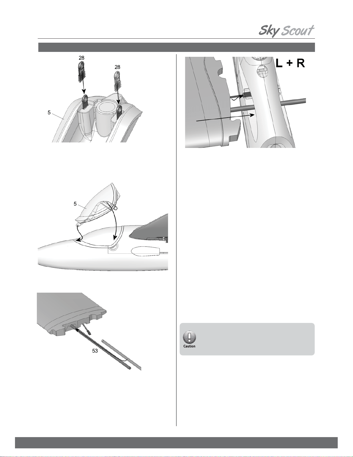
&RPSOHWLQJWKHFDQRS\
*lue the latch tongues in the recesses in the canopy .
8se thick CA glue initially, and ¿t the canopy on the model immediately,
so that the latch components align themselves automatically. Wait for at
least two minutes before removing the canopy, then apply drops of thin CA
glue to the gaps in the latches to glue them in place, Àush with the foam.
,QVWDOOLQJWKHÀLJKWEDWWHU\DQGUHFHLYHU
Deploy the receiver aerialsas described in the RC system instructions.
The aerial tube installed in the underside of the fuselage is intended for
conventional MH]systems. If you are using a .4*H]system, cut slits
in the foam material e.g. in the area of the canopy Àangeand press the
short aerials into them.
127( When positioning these components you should bear in mind
the recommended Center of *ravity C* at point . Stick the strips of
Velcro tape and loop sideto the inside of the fuselage Àoor. Note
that the adhesive on the tape is not adequate for this application, so ¿x
the tape with CA glue for additional security.
The ¿nal position of the Àight battery is determined when you check the
model’s balance point Center of *ravity - C*. Check to make sure that
the Velcro tape for the Àight battery is ¿rmly secured. If you neglect this,
your battery could come loose in Àight. $OZD\VFKHFNWKDWWKHÀLJKW
SDFNLVVHFXUHEHIRUHHYHU\ÀLJKW
Connect the servo leads to the receiver. Switch the transmitter on, then
connect the Àight battery in the model to the speed controller, and the
controller to the receiver. This model requires a BEC-type speed controller
receiver power supply from the Àight battery.
Now switch the motor on brieÀy, and check once more that the propeller
rotates in the correct direction clockwise looking at the spinner. If it spins
in the reverse direction, switch any two of the three motor wires to correct it.
Always hold the model securely when testing the power system, and
remove any loose, lightweight objects before and behind the model before
the propeller does it for you.
)LQLVKLQJWKHPRGHO
The kit includes a multi-color decal sheet A Bfor adding the ¿nal
touches to the model. Cut out the individual decals and apply them to the
airplane in the arrangement shown on the box illustration.
The canopy can be colored black using a waterproof felt-tip pen. If you
wish to apply an all-over color scheme, you can use most common spray
enamel paints available at your local hardware store. You must use
caution and not over apply the paint instead spraying several light coats.
For tips on painting our models please refer to the FAQ section on our
website.
,QVWDOOLQJWKHZLQJV
Slide the wing joiner into one of the wing panels as shown in the
illustration, then ¿t the joiner through the fuselage. Before the wing makes
contact with the fuselage, connect the aileron servo lead to the extension
lead already installed in the fuselage.
Connect the plug and socket, then push the wing fully into place; the cable
will now form itself into a loop in the space designed for it.
Fit the other wing panel onto the joiner, and connect the aileron servo
lead to the extension lead already installed in the fuselage, as described
previously.
Do not connect the battery to the speed controller until you
have switched the transmitter on, and are certain that the
throttle control is at the “OFF” position.
Even small motors and propellers are capable of inÀicting
injury

15
Fly high with Hitec
zG{aGwGGtGGm
Before attempting Àight ensure that your controls are set up properly and give the appropriate response to your transmitter inputs. A complete set up
guide appears at the end of this manual in $SSHQGL[%7UDQVPLWWHU&RQWURO6XUIDFH0RYHPHQWV. If you have any questions about this consult with a
local experienced Àier or your local RC Hobby Retailer or contact Hitec Customer Support.
1. Check Transmitter Inputs
It is important to set the correct control surface travels, otherwise your model will not respond to your control commands smoothly and evenly. To do
this you need to complete all the electrical connections as described in the RC system instructions.
127( when we refer to a model aircraft, the terms “right” and “left” always apply to the model when viewed from above, with the nose pointing away
from the you.
(/(9$725 8p-elevator stick back, towards youshould be about 5 mm; down elevator stick forward, away from youapprox. 4 mm.
58''(5 The rudder should move 10 mm to either side of center, as measured from the widest part of the control surface.
$,/(5216 The ailerons should deÀect mm up and 4 mm down. When you move the aileron stick to the right, the aileron on the right-hand wing
should deÀect up; that on the left-hand wing down. If your radio control system does not include the required mixing to set up differential aileron travel
as described above, the model will still Ày well with symmetrical non-differentialtravels. If you are a beginner, you will probably notice no difference in
any case. However, accurate rolling maneuvers are more dif¿cult to Ày with symmetrical aileron travels.
127( If you cannot set the recommended travels using your transmitter’s adjustment facilities, you will have to re-position the pushrod connections,
using different holes at the servo or horn.
2. Setting the control surface travels
Like every aircraft, your Sky Scout must be balanced correctly if it is to Ày well and stably. To check the Center of *ravity C* you must ¿rst assemble
your model completely as if you were ready to Ày, and install the Àight battery.
7KHFRUUHFW&*LVPDUNHGDWDSRLQWDERXWPPIURPWKHUHDUHGJHRIWKHZLQJMRLQHUFRYHUDQGWKHPRGHOPXVWEDODQFHDWWKLVSRLQW7KLV
VHWWLQJFRUUHVSRQGVWRDERXWPPDIWRIWKHZLQJURRWOHDGLQJHGJHPHDVXUHGHLWKHUVLGHRIWKHIXVHODJH
Support the model under both wings on two ¿ngertips at the marked point, and it should balance level.
Minor corrections can be made by adjusting the position of the Àight battery. Once you have established the correct position for the battery, mark this in
the fuselage to ensure that it is always positioned correctly.
3. Balancing the model
Safety is of the utmost importance when Àying any model aircraft. Third party insurance is mandatory. If you join a model club or association, suitable
coverage will usually be available through the organi]ation. It is your personal responsibility to ensure that your insurance is adequate i.e. that its cover
includes powered model aircraft.
Always Ày in such a way that you do not endanger yourself or others. Bear in mind that even the best RC systems are subject to outside interference.
No matter how many years of accident-free Àying you have there is always the possibility of an unforeseen problem or error that can cause an accident
Make it your job to keep your models and your radio control system in perfect operating condition at all times.
Check and observe the correct charging procedure for the batteries you are using.
%HIRUHHYHU\ÀLJKWFKHFNWKDWWKHEDWWHU\WKHZLQJVDQGWKHWDLOSDQHOVDUHDWWDFKHGDQG¿UPO\VHDWHG&KHFNLQWXUQWKDWHDFKFRQWURO
VXUIDFHLVRSHUDWLQJFRUUHFWO\
:KHUHWRÀ\±8VLQJ$LU¿HOGV
18se an of¿cial model air¿eld if possible when Àying your model.
Check that other pilots and spectators are positioned safely before Àying your model.
3Wait for other pilots to land their models if they are Àying already.
4Always remember that the pilot is responsible for any outcome that may occur during the Àight.
5Do not Ày the plane behind yourself or others.
6Seek help from an experienced pilot for your ¿rst Àight.
7Do not Ày under the inÀuence of alcohol or drugs or if you are feeling ill.
Be sure to do pre-Àight safety checks of the model before Àying.
4. Safety
If you have no prior experience with Àying a radio controlled model, please take the time to read through the “Appendix A” entitled “The
basics of model Àying”.

16
Fly high with Hitec
The following checks are done with the radios system turned on and the model’s main battery plugged in and fully charged. Be sure to turn on the
transmitter and check to make sure that the throttle is in the2)) position %()25( connecting the main battery. If using a conventional ;; MH]fre-
quency system, ensure that your chosen channel is free before beginning these tests.
a5DQJH&KHFNFollow the instructions provided by your RC system manufacturer. The transmitter battery and Àight pack must be fully
charged in accordance with the manufacturer’s recommendations before conducting this test.
b)XQFWLRQ&KHFN Check to make sure the model responds correctly to the transmitter inputs.
If you are unsure about the proper range, operation or functionality of any part of the radio system, do not Ày the modelIf you cannot identify and solve
the problem, send the whole RC system including battery, switch harness and servosto your system manufacturer for inspection.
The following inspection should be done %()25( plugging in the battery.
aCheck to make sure the models is in safe operating condition and that there is no damage to the wings or the tail.
bCheck to ensure the wings and tail plane are properly seated and locked into position
cMake sure the prop and hub are tightly mounted to the motor
dMake sure the propeller spins freely and that the blades open and close properly
1. Pre-flight Model Inspection
2. Pre-flight Radio Check
The following is based on common safety precautions for Àying RC models. Please read the following information before attempting to Ày your model.
Check all safety aspects of your model before Àying for a safe Àight.
Pre-Flight Inspections and Cautionary Notes
wTGGG
The following instructions are for users to easily understand what to check for before the Àight how to take-off, land and adjust settings during the Àight.
The instruction manual cannot address every situation that may occur, but it does explain common situations that occur which could be useful for you
when Àying.
1. Check whether the wings or the tail are damaged.
. Check if the joints and the propeller are assembled ¿rmly.
3. Connect the main battery AFTER turning on the transmitter. Keep away from other people, and especially away from the propeller.
4. Once the main battery is connected the motor could start suddenly for many reasons or due to an error. Be sure to have another person hold the
model down before connecting the battery or turning the power on.
5. Check whether the model responds correctly to the radio signals.
zGmaGmGGtG
tGm
For the ¿rst Àight wait for a day with as little bree]e as possible; the evening hours often offer calmer conditions The aircraft is designed to be hand-
launched always into wind. If you are a beginner to model Àying, we strongly recommend that you ask an experienced modeler to help you for the ¿rst
few Àights. The following instructions are for users to easily understand the process of taking off, making in Àight adjustments and landing the model.
The instruction manual cannot address every situation that may occur, but it does explain common situations that occur which could be useful for you
when Àying. Beginner Àiers should seek help of an experienced pilot through a friend, local club or nearby RC hobby retailer.
Using excessive control stick inputs can cause in undesired results. Control stick inputs should be small and slight until you have
become familiar with the way the model behaves.

17
Fly high with Hitec
1. Taking Off
Hold the plane facing into the wind and keep it level as you apply the throttle. Now throw it smoothly forward with the nose level or angled up no more
than 30-degrees. After the take-off use the control sticks to keep the wings and fuselage level as the model gains altitude. If the battery isn’t fully
charged, the plane will not climb normally. Once you have climbed to an altitude of 100-130 feet 30-40 metershigh you can adjust the trim to make it
Ày smoothly.
zGmaGmGGtG
2. Adjusting the Trims
3. How to Control the Plane
4. How to Land the Plane
Even if you balance the plane properly on land, it may not Ày hori]ontally due to the wind or weight shift. To check the trim, once you have reached your
initial climb altitude, set the throttle to about ¾ power and let go of the control sticks. If the plane turns to the right, adjust the rudder trim control on your
transmitter to the left. If the plane continues to climb, adjust the elevator trim up. Adjust the rudder and elevator trim controls so that the plane will Ày
straight and level when you let go of the control sticks. Be sure to adjust the trim only after the plane has reached an altitude of more than 130 feet 40
meters. Adjusting the trim when the plane is Àying too low could cause it to crash.
The most basic Àight pattern for your new plane is an oval shape. Fly the plane in one direction at a safe altitude until you are familiar with the control
sticks. When moving in a straight line, slightly adjust the control sticks to keep the plane level.
To turn to the left, move the rudder stick slightly to the left and note the plane’s reaction. It should begin turning to the left while also losing a little bit of
altitude. To maintain its altitude in a turn a pull the elevator stick toward you slightly at the same time. To complete the turn let both sticks spring back to
their neutral position.
To turn to the right, move the rudder stick slightly to the right and pull the elevator stick toward you slightly at the same time. To complete the turn let
both sticks spring back to their neutral position.
With the aircraft Àying at an adequate altitude, check how it responds when the motor is switched off, so that you are familiar with its behavior during the
gliding process.
Avoid Àying tight turns at ¿rst, especially close to the ground, and in particular during the landing approach.
You must land the plane before the battery is too low. It is always better to land safely some distance away than to risk a crash by forcing the model
back to your feet.
In order to land the plane safely, have a friend ¿rst check for any obstacles or people around the intended landing area. With the model Àying into the
wind reduce the power so the model starts descending. Use the control sticks to keep the wings and fuselage level until it touches down.
You could damage the plane if it lands too steeply on its nose or hits a wing tip ¿rst. Landing into the wind ensures the slowest possible landing and
least chance of damage.
5. After Your Flight
Immediately disconnect the Àight battery and then turn off your transmitter. Inspect the model for any damage and realign the wings and tail if neces-
sary. Completely recharge your battery according to the manufacturer’s speci¿cations before Àying again.

18
Fly high with Hitec
zGmaGyGwGGjG
Decal Sheet
Fuselage shells + snakes
Canopy
Tailplane
Wings
Small items set

19
Fly high with Hitec
zGmaGyGwGGjG
Injected parts
Twin control surface horn and pushrod connector, pcs.
Spar tube
Canopy-Lock pair
Driver, propeller boss and spinner
includes part 73 300, 5x o-rings
Driver, propeller boss and spinner
includes part 73 300, 5x o-rings

20
Fly high with Hitec
zGmaGjGzG
Table of contents
Other Hi-Tec Toy manuals


Popular Toy manuals by other brands

Eduard
Eduard Mosquito FB Mk.VI radiators quick start guide

Metcalfe
Metcalfe PN138 N GAUGE WAYSIDE STATION KIT instruction sheet

AeroWorks
AeroWorks 50cc EXTRA 260 ARF-QB Assembly manual

marklin
marklin Starter Set 29166 instruction manual

Mega Construx
Mega Construx Probuilder Viking Longship Raid Instruction

Badger Basket
Badger Basket 01857 Assembly instructions


Power Wheels
Power Wheels DRH62 owner's manual

Fisher-Price
Fisher-Price Disney Tot Rod R2510 Assembly and owner's manual

MinimumRC
MinimumRC F8F Rare Bear Install manual

Seagull
Seagull Space Walker II Assembly manual

Eduard
Eduard Bismarck part 6 quick start guide

Eduard
Eduard E-2C 2000 S.A. Assembly instructions