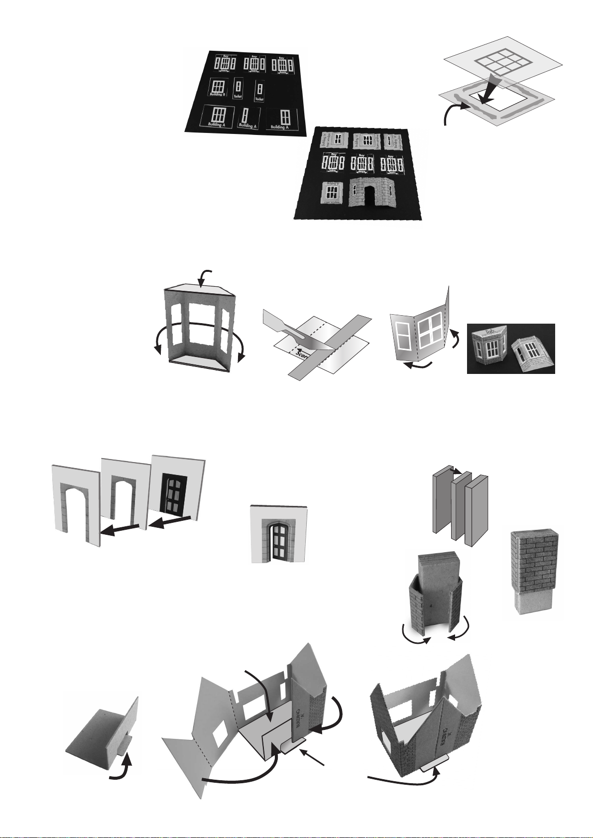
1 x PRINTED SHEET - Components for all buildings.
1 x PLAIN GREY CARD X- Interior strengthening parts.
1 x PLAIN GREY CARD Y- Interior strengthening parts.
1 x LASER-CUT CARD - Canopy edging and brackets.
1 x GLAZING SHEET.
2 x INSTRUCTION SHEETS.
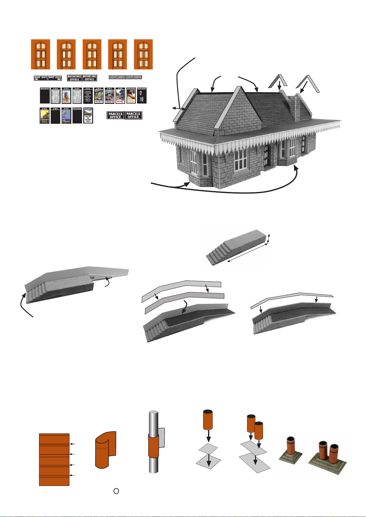
1 x Ridge Tile Sheet.
1 x Chimney pots, posters and extra doors sheet
PN138 N GAUGE
WAYSIDE STATION KIT
INSTRUCTION SHEET 1
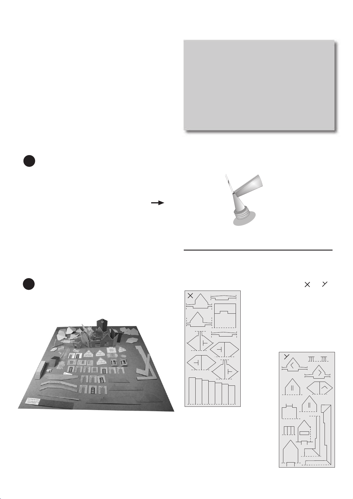
To make the
nozzle smaller,
put a piece of
wire from a
medium size
paper clip or a
large pin inside.
Although the 20ml. tubes of UHU have narrow nozzles, they
are still a bit too big
If using the glue frequently, it is not necessary to keep
replacing the pin in the nozzle. Simply place the tube
upright in an empty cup when not in use.
Then with a pair of pliers
nip one side of the nozzle
tightly, so that it squeezes
the soft metal around
the pin.
Keep the pin in the nozzle
when not in use to stop
it from blocking up.
UHU GLUE TUBES
To construct this kit you will need the following:
1. A Modellers knife.
2. A pair of sharp pointed scissors.
3. A steel ruler.
4. Glue - UHU Clear Adhesive is our favourite.
5. A cutting surface - a sheet of card or a cutting mat.
6. Fine point tweezers to hold the smaller components.
7. Water colour paints and a very fine brush, for
painting the edges and corners (optional).
READ THROUGH ALL THE
INSTRUCTIONS BEFORE YOU START.
GETTING STARTED
CHECK LIST
This kit pack should contain the following:
The awnings and brackets have been laser cut for finer detail
and are contained on a separate cream coloured sheet.
THESE ARE BEST LEFT ALONE ON THIS SHEET UNTIL
YOU HAVE BUILT THE MAIN BODY OF THE KIT.
The diagram (Fig. 15.) show the lines that you will need
to cut to release the components from the sheet.
PLEASE NOTE: Don’t throw anything away. Keep all offcuts
and waste card in a box until the kit is finished, just in case
you can’t find anything. The chances are that it will be there.
PLAIN GREY CARD COMPONENTS.
These thick card pieces are used within the kit to strengthen
and thicken parts of the kit. The dotted lines indicate where
you need to cut to release from base sheet.
There are two sheets of card, marked top corner and
2
1
1
3
3
4
4
5
5
6
7
8
9
10
11
12 13
14 15
16
8
10
SHEET X.
1. Building B roof & canopy support.
2. Building A inner floor.
3. Building B canopy supports x 2.
4. Building A gable inner wall spacers x 2.
5. Building A roof & canopy supports x 2.
6. Platform steps x 7
SHEET Y.
7. Small canopy beams x 2
8. Building C roof & canopy supports x 2.
9. Building C gable wall spacer.
10. Building B gable inner wall spacers x 2.
11. Building B inner floor thickener.
12. 3 x Large chimney stack inner formers.
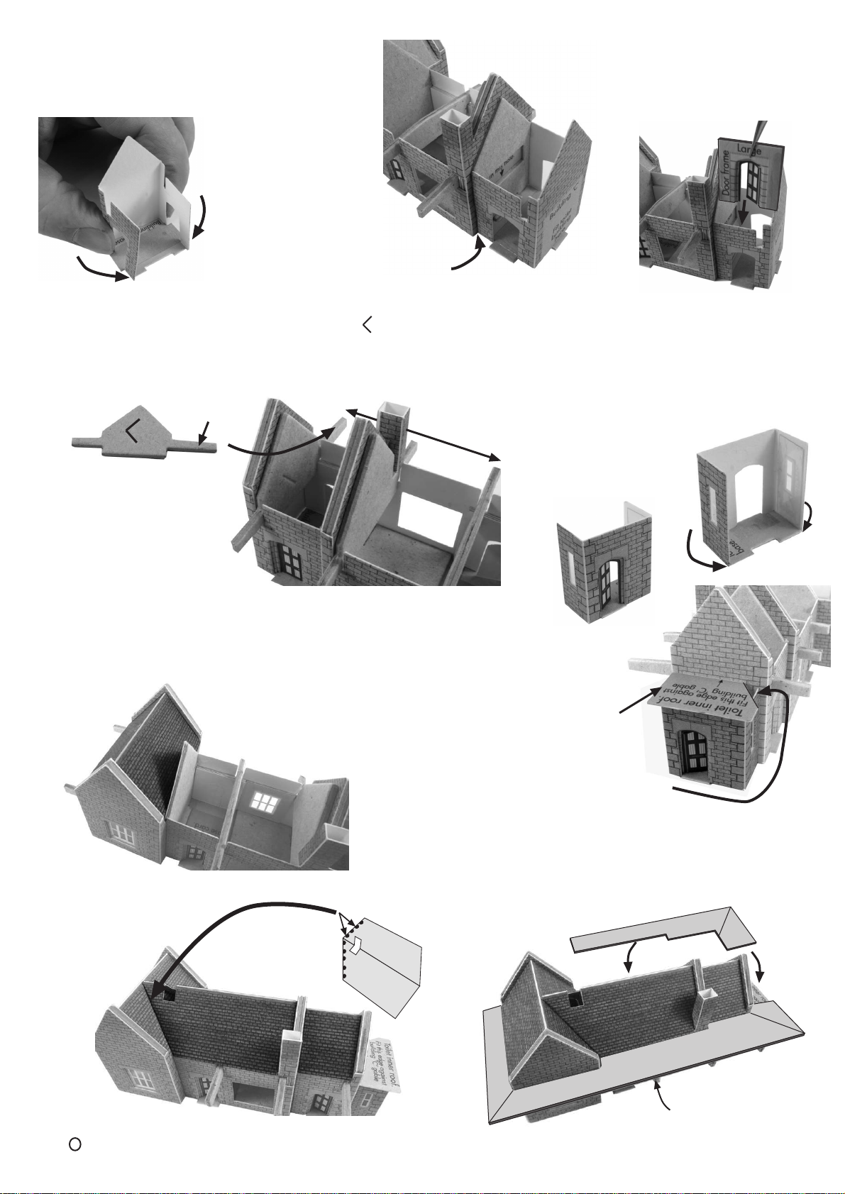
13. Building C inner gable end wall.
14. Building B inner gable end wall.
15/16 Canopy lower roof units.
To stop the components from falling off the sheets, they
are held secure with scorelines. These are cuts that only
go about 75% of the way through the card.
To release them simply run the point of your knife along
the scorelines and they will come seamlessly away.
These scorelines are indicated with blue arrows:
WARNING, Cut with care using a knife that is not too
sharp, this will reduce the risk of the blade running out
of the score and cutting the kit components.
1EXTRACTING COMPONENTS FROM SHEETS.
2MAKE YOUR ‘BUILDERS YARD’.
This is an area kept away from your working surface, where
you store ALL components extracted from the base sheets
until needed.
Use a piece of thick card or a tray to make your builders yard.
LASER CUT SHEET.
Your WORKING area should have a clean flat surface, and
should only contain the kit parts you are actually working on.
EVERYTHING ELSE SHOULD BE KEPT NEATLY ARRANGED
IN THE BUILDERSYARD, UNTIL NEEDED.