Seagull Space Walker II User manual

Kit features.
• Ready-made—minimalassembly&finishingrequired.
• Ready-coveredcovering.
• Photo-illustratedstep-by-stepAssemblyManual.
MadeinVietnam.
Specifications
WingSpan-------------------------------50in---------------------127cm.
WingArea-------------------------------217sqin------------14sqdm.
Weight------------------------------------30-42oz---------850-1200g.
Length------------------------------------ 39in-----------------------99cm.
Radio------------------------------4channelwith4sub-microservos.
Motorsize -----------------------------HimarkOutrunnerC3522-990.
Need to Complete
Speed Control: SJ Conquest 35 or 45 amp.
RecommendedBattery3-cell 11.1V 2200mAh to 3200mAh Li-Po.
ASSEMBLY MANUAL
MS:X6

SPACE WALKER II. Instruction Manual.
2
INTRODUCTION.
Thankyouforchoosing the SPACE WALKER II ARTFby SEAGULLEP. The SPACE WALKER
IIwasdesignedwiththeintermediate/advancedsportflyerinmind.Itisa semiscale airplane which
is easy to fly and quick to assemble. The airframe is conventionally built using balsa, plywood to
make it stronger than the average ARTF , yet the design allows the aeroplane to be kept light. You
willfindthatmostoftheworkhasbeendoneforyoualready.FlyingtheSPACEWALKERIIissimply
ajoy.
This instruction manual is designed to help you build a great flying aeroplane. Please read this
manualthoroughlybeforestartingassemblyofyourSPACEWALKERII.Usethepartslistingbelow
to identify all parts.
WARNING.
Please be aware that this aeroplane is not a toy and if assembled or used incorrectly it is
capable of causing injury to people or property. WHEN YOU FLY THIS AEROPLANE YOU
ASSUME ALL RISK & RESPONSIBILITY.
If you are inexperienced with basic R/C flight we strongly recommend you contact your R/C
supplierandjoinyourlocalR/CModelFlyingClub.R/CModelFlyingClubsofferavarietyoftraining
proceduresdesignedtohelpthenewpilotonhiswaytosuccessfulR/Cflight.Theywillalsobeable
to advise on any insurance and safety regulations that may apply.
ADDITIONAL ITEMS REQUIRED.
! Motor: Himark outrunner
C3522-990
!Radio with four sub-micro servos.! Speed control: 35A to 45A.
!Battery: Awesome Power battery
11.1V 2200 mAh - 11.1V 3200 mAh.
Himark outrunner
C3522-990.
Speed control:
SJ Conquest 35 or 45 amp.
Awesome Power battery
11.1V 2200 mAh - 11.1V 3200 mAh.

www.seagullmodels.com
3
NOTE: To avoid scratching your new aero-
planewesuggestthatyoucoveryour
workbench with an old towel. Keep a
couple of jars or bowls handy to hold
the small parts after you open the
bags.
Pleasetrialfitallparts.Makesureyou
have the correct parts and that they
fit and are aligned properly before
gluing! This will ensure proper as-
semblyasthe SPACE WALKER IIis
made from natural materials and
minor adjustments may have to be
made.
The paint and plastic parts used in
this kit are fuel proof. However, they
arenottolerantofmanyharshchemi-
cals including the following: paint
thinner, cyano-acrylate glue accel-
erator,cyanoacrylategluede-bonder
andacetone.Do not letthesechemi-
calscome incontact with the colours
onthecovering and theplasticparts.
TOOLS & SUPPLIES NEEDED.
!Thick cyanoacrylate glue.
!30 minute epoxy.
!5 minute epoxy.
!Hand or electric drill.
!Assorted drill bits.
!Modellingknife.
!Straight edge ruler.
!2mm ball driver.
!Phillips head screwdriver.
!220 grit sandpaper.
!90° square or builder’s triangle.
!Wire cutters.
!Masking tape & T-pins.
!Thread-lock.
!Paper towels.
SPACE WALKER II. Instruction Manual.
4
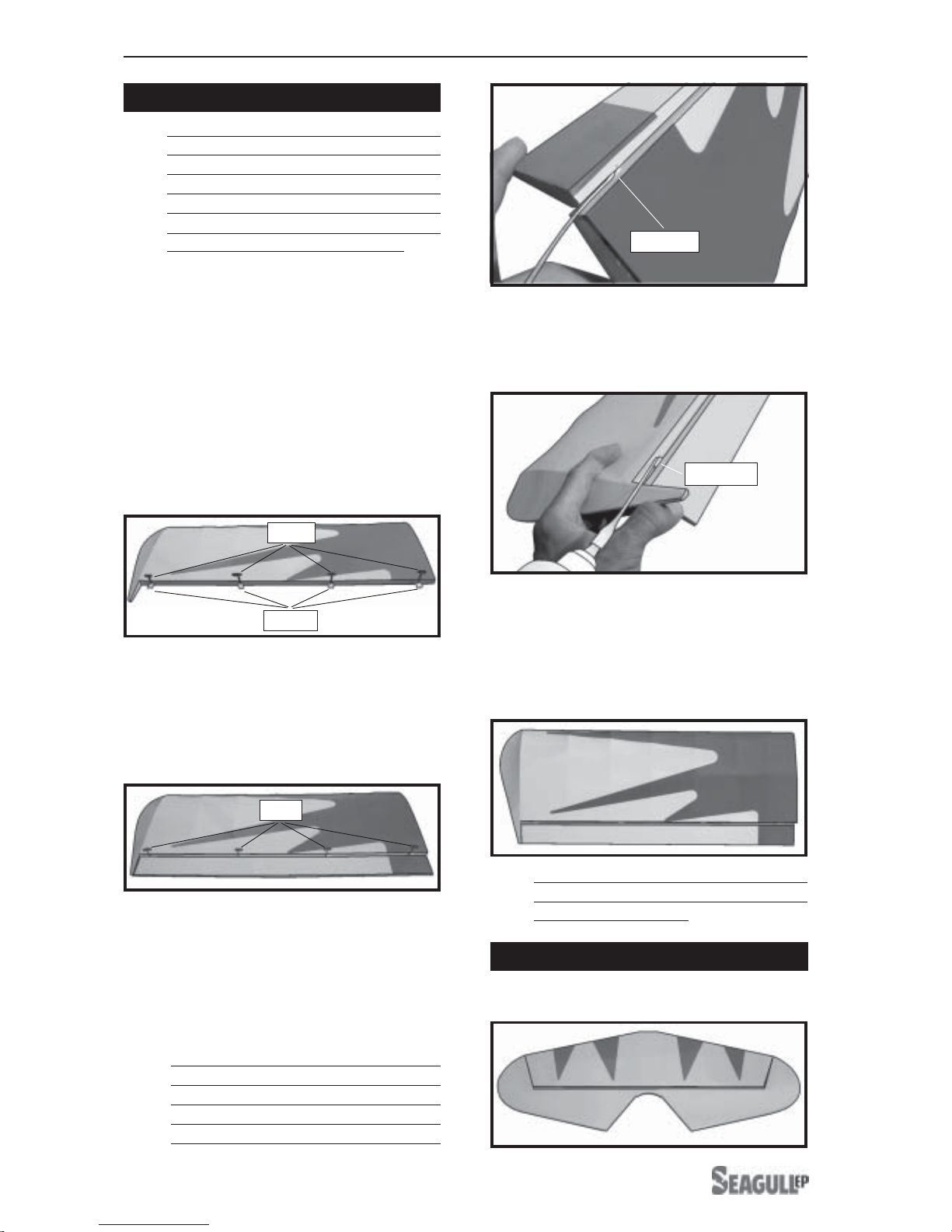
!1) Carefully remove the aileron from one
of the wing panels. Note the position of the
hinges.
!2)Removeeach hinge fromthewing panel
and aileron and place a T-pin in the center of
each hinge. Slide each hinge into the wing
panel until the T-pin is snug against the wing
panel. This will help ensure an equal amount
ofhingeison either sideofthehinge line when
the aileron is mounted to the aileron.
HINGING THE AILERONS.
Work the aileron up and down several
times to “work in” the hinges and check
for proper movement.
!3) Slide the wing panel on the aileron until
there is only a slight gap. The hinge is now
centered on the wing panel and aileron.
Remove the T-pins and snug the aileron
against the wing panel.A gap of 1/64” or less
shouldbe maintained betweenthe wingpanel
andaileron.
HINGING THE ELEVATOR.
Note:
!5)Turnthe wingpanel over and deflect the
aileron in the opposite direction from the
opposite side. Apply thin C/A glue to each
hinge,makingsurethatthe C/A penetrates into
both the aileron and wing panel.
Glue the elevator hinges in place using the
same tectniques used to hinge the ailerons.
The control surfaces, including the
ailerons, elevators, and rudder, are
prehinged with hinges installed, but the
hinges are not glued in place. It is
imperativethat youproperly adhere the
hingesin placeper the steps that follow
using a high-quality thin C/A glue.
Note:
Hinge.
T-pin.
T-pin.
!4)Deflect the aileron and completely
saturate each hinge with thin C/A glue. The
aileronsfrontsurfaceshould lightly contactthe
wing during this procedure. Ideally, when the
The hinge is constructed of a special
material that allows the C/A to wick or
penetrateanddistribute throughout the
hinge, securely bonding it to the wood
structureof the wingpanel andaileron.
hinges are glued in place, a 1/64” gap or less
will be maintained throughout the lengh of the
aileron to the wing panel hinge line.
Note:
C/Aglue.
C/Aglue.
!7) Repeat this process with the other wing
panel, securely hinging the aileron in place.
!6) Using C/A remover/debonder and a
papertowel, remove anyexcess C/A gluethat
may have accumulated on the wing or in the
aileronhinge area.

www.seagullmodels.com
5
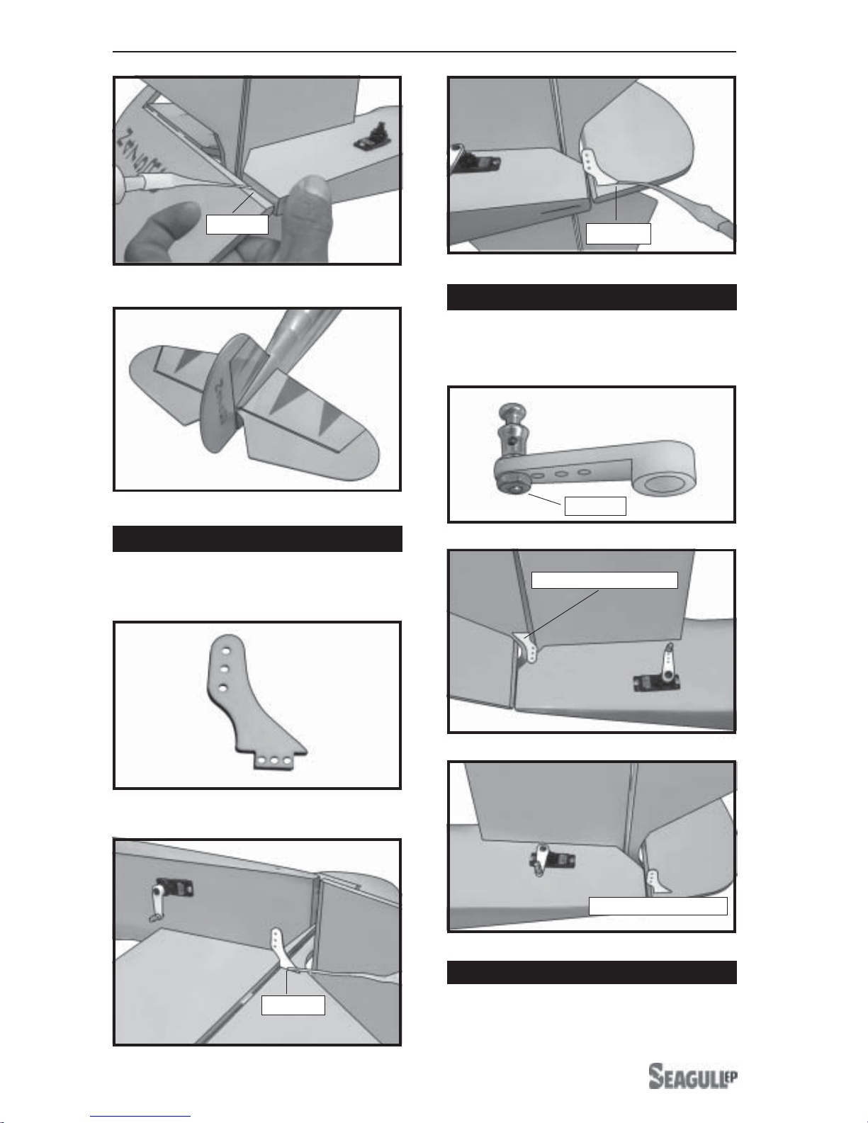
HINGING THE RUDDER.
Glue the rudder hinges in place using the
same tectniques used to hinge the ailerons.
Assemble and mounting the wheel pants
as shown in the following pictures.
WHEEL AND WHEEL PANTS.
C/Aglue.
C/Aglue.
C/Aglue.
C/Aglue.

SPACE WALKER II. Instruction Manual.
6
Using the hardware provided, mount the
main landing gear to the fuselage.
INSTALLING THE MAIN LANDING GEAR.
A drop of C/A glue on the wheel collar
screws will help keep them from coming lose
duringoperation.
Repeat the process for the other wheel.
INSTALLING ELECTRIC MOTOR.
COWLING INSTALLATION.
!1) Using a pen to mark the points follow-
ing the instruction below.
!2) Slide the fiberglass cowl over the en-
gineandline up thebackedge ofthecowl with
themarks youmade on the fuselage thentrim
and cut.
1.5cm. 1cm.
6.5cm.
Rotor shaft.
Motor.
Front view.
2 X 12mm.

www.seagullmodels.com
7
AILERON SERVOS-LINKAGES.
Install the rubber grommets and brass
collets onto the aileron servo. Test fit the
servo into the aileron servo mount.
! 1) Install the rubber grommets and brass
eyelets onto the aileron servo.
! 2) Install the metal connector onto servo
arm.
Because the size of servos differ, you
mayneedtoadjustthesizeofthe precut open-
ing in the mount. The notch in the sides of
themountallowtheservoleadtopassthrough.
!3) While keeping the back edge of the
cowl flush with the marks, align the front of
thecowl withthe crankshaftof the motor. The
front of the cowl should be positioned so the
crankshaft is in nearly the middle of the cowl
opening.Usethespinnerbackplateasaguide.
Hold the cowl firmly in place using pieces of
masking tape.
!4) Slide the cowl back over the motor.
The propeller should not touch any part
of the spinner cone. If it does, use a sharp
modeling knife and carefully trim away the
spinner cone where the propeller comes in
contact with it.
2 x 8mm.
2x8mm.
Using a small weight (Weighted fuel pick-up
workswell)and thread, feedthestring through
the wing as indicated.
!3) Turn the wing panel right side up. Using
amodelingknife,removethecoveringat servo
tray.
Thread.
Small weight.

SPACE WALKER II. Instruction Manual.
8
Attach the micro control connector to the
servo arms. Be sure to use the lock tie but it
could free rotation .
Wing bottom.
Wing bottom.
Plastic tape.
! 4) Insertaileron control hornto the aileron.
Attach the thread to the servo lead and
carefully thread it though the wing.
Wing bottom.
Thread.
Small weight.
Secure the servos with the screws pro-
vided with your radio system.
Electric wire.
Thread.
Lock tie.
Aileroncontrol horn slot.

www.seagullmodels.com
9
Aileron
control horn.
C/Aglue.
Repeat the procedure for orther wing
haft.
!1) Locate and cut out the covering film
fromthe servo holes in bothsides offuselage.
FUSELAGE SERVO INSTALLATION.
Rightside. Remove covering.
INSTALLING THE SWITCH.
Installthe switch intothe precut holein the
side, in the fuselage.
!2) Installthe rubbergrommets andbrass
collets onto the elevator servo. Test fit the
servo into the elevator servo mount.
!3)Secure theservos withthe screws pro-
vided with your radio system.
Because the size of servos differ, you
mayneedtoadjustthe size of theprecutopen-
ing in the mount. The notch in the sides of the
mount allow the servo lead to pass through.
Left side.
Rudder servo.
Rightside.
Elevator servo.
Remove covering.
Pushrod wire.
Control horn.

SPACE WALKER II. Instruction Manual.
10
! 7) When you are sure that everything is
alignedcorrectly,apply C/Agluetothe top and
bottom of the stabilizer mounting area and to
the stabilizer mounting platform sides.
! 5) Remove the stabilizer. Using the lines
youjust drewas a guide, carefully removethe
covering from between them using a model-
ingknife.
When cuttingthrough the coveringto re-
moveit, cut with only enoughpressure to only
cut through the covering itself. Cutting into
the balsa structure may weaken it.
! 6) Using a modeling knife, carefully re-
move the covering that overlaps the stabilizer
mounting platform sides in the fuselage. Re-
move the covering from both the top and the
bottom of the platform sides.
HORIZONTALSTABILIZER.
!2)Usingamodeling knife, carefully remove
thecovering at mountingslotof horizontalsta-
bilizer ( both side of fuselage).
!1) Using a ruler and a pen, locate the
centerlineof thehorizontalstabilizer,atthetrail-
ing edge, and place a mark. Use a triangle
and extend this mark, from back to front,
across the top of the stabilizer. Also extend
thismark downthe backof the trailing edge of
the stabilizer.
! 3) Slide the stabilizer into place in the pre-
cut slot in the rear of the fuselage. The stabi-
lizer should be pushed firmly against the front
of the slot.
! 4) With the stabilizer held firmly in place,
use a pen and draw lines onto the stabilizer
where it and the fuselage sides meet. Do this
on both the right and left sides and top and
bottom of the stabilizer.
Switch.
Center line.
Pen.
Removecovering.

www.seagullmodels.com
11
Hinge.
!1) Using a modeling knife, remove the
covering from over the precut hinge slot cut
intothelowerrearportionof the fuselage. This
slot accepts the lower rudder hinge.
VERTICAL STABILIZER INSTALLATION.
!3) While holding the vertical stabilizer
firmly in place, use a pen and draw a line on
each side of the vertical stabilizer where it
meets the top of the fuselage.
!2) Slidethe verticalstabilizer into the slot
in the top of the fuselage. The rear edge of
thestabilizer shouldbe flushwiththerearedge
of the fuselage and the lower rudder hinge
should engage the precut hinge slot in the
lowerfuselage. The bottomedge of the stabi-
lizer should also be firmly pushed against the
top of the horizontal stabilizer.
Hingeslot.
When cutting through the covering to re-
moveit, cut with only enoughpressure to only
cut through the covering itself. Cutting into
the balsa structure may weaken it.
!5) Slide the vertical stabilizer back in
place. Using a triangle, check to ensure that
thevertical stabilizeris aligned 90ºto thehori-
zontal stabilizer.
90º
Vertical
Stabilizer.
Horizontal
Stabilizer.
! 6) When you are sure that everything is
aligned correctly, apply C/Aglue to fix them.
!4) Remove the stabilizer. Using a mod-
eling knife, remove the covering from below
the lines you drew. Also remove the covering
from the bottom edge of the stabilizer and the
bottomandtop edges ofthefillerblock. Leave
the covering in place on the sides of the filler
block.
Pen.
Remove
covering.
SPACE WALKER II. Instruction Manual.
12
Attach the micro control connector to the
servo arms. Be sure to use the lock tie but it
could free rotation .
SERVO ARM INSTALLATION.
C/Aglue.
Control horn install as same as method of
aileron wing. See pictures below.
CONTROL HORN INSTALLATION.
Lock tie.
Rudder control horn.
Pushrod install as same as method of
pushrod wing. See pictures below.
PUSHROD INSTALLATION.
C/Aglue.
C/Aglue.
Elevator control horn.

www.seagullmodels.com
13
MOUNTING THE TAIL SKID.
See pictures below:
Pushrod.
Rudder
servo.
Elevator servo.
Expoyglue.
INSTALLING THE BATTERY-RECEIVER.
See pictures below.
Receiver.
Tie wrap.
Battery.
Tie wrap.

SPACE WALKER II. Instruction Manual.
14
BALANCING.
!1) It is critical that your airplane be bal-
anced correctly. Improper balance will cause
yourplaneto losecontroland crash. The cen-
ter of gravity is locate 8.5cm back from the
leading edge of the wing, measured at wing
tip.
!2) If the nose of the plane falls, the plane
is nose heavy. To correct this first move the
battery pack further back in the fuselage. If
this is not possible or does not correct it, stick
small amounts of lead weight on the fuselage
sides under the horizontal stabilizer. If the tail
of the plane falls, the plane is tail heavy. To
correctthis, move thebatteryand receiverfor-
ward orif this is not possible, stick weight onto
thefirewall. When balanced correctly, the air-
plane should sit level or slightly nose down
when you lift it up with your fingers.
Insert two wing panels as pictures below.
ATTACHMENT WING-FUSELAGE.
Attach the aluminium tube into fuselage.
2 x 8mm.
2 x 8mm.
Wing bolt.
Wing bolt.

www.seagullmodels.com
15
! 3) When the elevator, rudder and aileron
control surfaces are centered, use a ruler and
check the amount of the control throw in each
surface. The control throws should be
measured at the widest point of each sur-
face!
!2) Turn onthe radiosystem, and with the
trim tabs on the transmitter in neutral, center
the control surfaces by making adjustments
totheclevises or adjustableservoconnectors.
The servo arms should be centered also.
!1) We highly recommend setting up the
SPACE WALKER II using the control throws
listed at right. We have listed control throws
for both Low Rate (initial test flying/sport fly-
ing) and High Rate (aerobatic flying).
! 4) By moving the position of the adjust-
able control horn out from the control surface,
you will decrease the amount of throw of that
control surface. Moving the adjustable con-
trol horn toward the control surface will in-
crease the amount of throw.
FLIGHT PREPARATION.
! A) Check the operation and direction of
the elevator, rudder, ailerons and throttle.
! B) Plug in your radio system per the
manufacturer's instructions and turn every-
thingon.
! E)Check the throttle.
! D) Check the rudder. Looking from be-
hindthe airplane, move the rudderstick tothe
right. Theruddershould movetothe right. If it
does not, flip the servo reversing switch on
your transmitter to change the direction.
! C) Check the elevator first. Pull back on
theelevator stick. Theelevator halves should
move up. If it they do not, flip the servo re-
versing switch on your transmitter to change
the direction.
INITIAL FLYING/SPORT FLYING
Do not use the aerobatic settings for
initial test flying or sport flying.
AEROBATIC FLYING
Ailerons: 3/8” up 3/8” down
Elevator : 1” up 1” down
Rudder : 2” right 2” left
Ailerons: 3/16” up 3/16” down
Elevator : 3/8” up 3/8” down
Rudder : 1” right 1” left
CONTROL THROWS.
!5) If your radio transmitter is equipped
withdual rate switchesdouble checkthat they
are on the low rate setting for your first few
flights.
!6) Check to ensure the control surfaces
are moving the proper amount for both low
and high rate settings.
!7) Check the receiver antenna. It should
be fully extended and not coiled up inside the
fuselage.
PREFLIGHT CHECK.
!1) Completely charge your transmitter
and receiver batteries before your first day of
flying.
!2) Check every bolt and every glue joint
in the SPACE WALKER II to ensure that ev-
erything is tight and well bonded.
!3) Double check the balance of the air-
plane. Do this with the fuel tank empty.
!4) Check the control surfaces. All should
move in the correct direction and not bind in
any way.
! F) From behind the airplane, look at the
ailerononthe right winghalf. Movetheaileron
sticktotheright. Therightaileronshouldmove
upand the otheraileron should movedown. If
it does not, flip the servo reversing switch on
your transmitter to change the direction.
!8) Properly balance thepropeller. Anout
of balance propeller will cause excessive vi-
bration which could lead to engine and/or air-
frame failure.
We wish you many safe and enjoy-
able flights with your SPACE WALKER
II.
Other manuals for Space Walker II
1
Table of contents
Other Seagull Toy manuals


