Hi TV Pure III User manual

II
To ensure driving safety, the front screen must be connected to the video out•
“Handbrake” control cable. This will ensure the driver’s concentration while the
vehicle is moving. The driver is able to watch TV once the handbrake is activat-
ed. The rear passenger screens are connected via the “Rear Video Out” control
cable and are not under the same restriction.
WARNING
To avoid electrical shock or bodily harm, please ensure the following
Do not remove enclosure•
Do not allow the unit to be exposed to extreme heat, cold or humid condition•
Do not connect the receiver with excessive voltage than indicated•
Emergency Handling
If the receiver is exhibiting any unusual behaviour, please turn off power imme-•
diately and contact your dealer for support. Do not attempt to repair the receiver.
Safety Guidelines

III
Suitable for DVB-T reception coverage area•
Receives both VHF & UHF signals•
Contains digital decoder & twin tuners•
Digital decoder will automatically performs error correction, which increases•
Signal to Noise (S/N) ratio and reception capacity
Supports both 4:3 and 16:9 image ratio•
Receives Standard digital TV programs•
Provides Electronic Program Guide (EPG) function•
CD quality sound, 24 bit processing for stereo sound output•
High quality DVD image•
SPECIAL ATTENTION
Please use the standard 75 Ohm antennas designed for digital TV. This machine•
provides a +5V DC power used by the antenna. The power can be used by an ac-
tive antenna.
If the antenna used has an impedance lower than the standard 75 Ohm or has•
short-circuited, the screen will display an “antenna power overload” warning
message. Please eliminate the antenna short-circuit or exchange it for a standard
digital TV antenna.
If no programs can be received, please check rst if the antennas are standard •
DVB-T antennas and if they are connected properly. Use the signal strength
indicator and signal status to make appropriates adjustments to the antenna po-
sition. If necessary, use the auto scan button to re-scan all channels. Still, if no
programs can be received, then the receiver is probably outside the coverage
area. Move the receiver to a new location and re-scan. Details about coverage
areas can be found from digital broadcasting organisation websites.
Digital Set-top Box Special features

IV
TABLE OF CONTENTS
REMOTE CONTROL 5
PRODUCT OVERVIEW 6
Front Panel
Rear Panel
Getting Start 8
Control Panel Usage................................ 8
Channel Function Menu ..................................9
Setting Function Menu ............................. 10
Search Function Menu ............................. 12
EPG (Electronic Program Guide)..................... 14
Multi-channel Audio............................... 14
SPECIFICATIONS 15
Hardware Specications
Front and Rear Summary
Software Feature
5
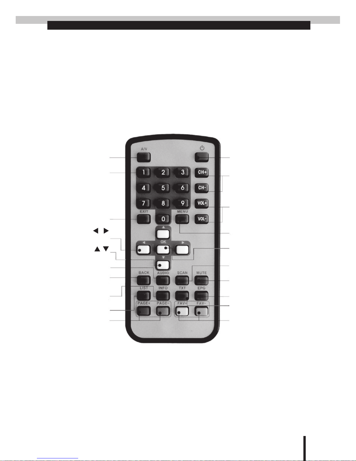
REMOTE CONTROL
Power toggle button for
mode
Channel number
up or down
Adjust the volume
Enter main menu
Auto Scan
power on or standby
Mutes the sound
Electronic Program Guide
Teletext
Favorite channel number
up or down
Page up or down
Channel list
View the current
program information
Channel Back
Multi-channel Audio
Up or down arrow
Left or right arrow
To exit menu
Audio/Video
switching button
Numeric Keys or
channel number
6
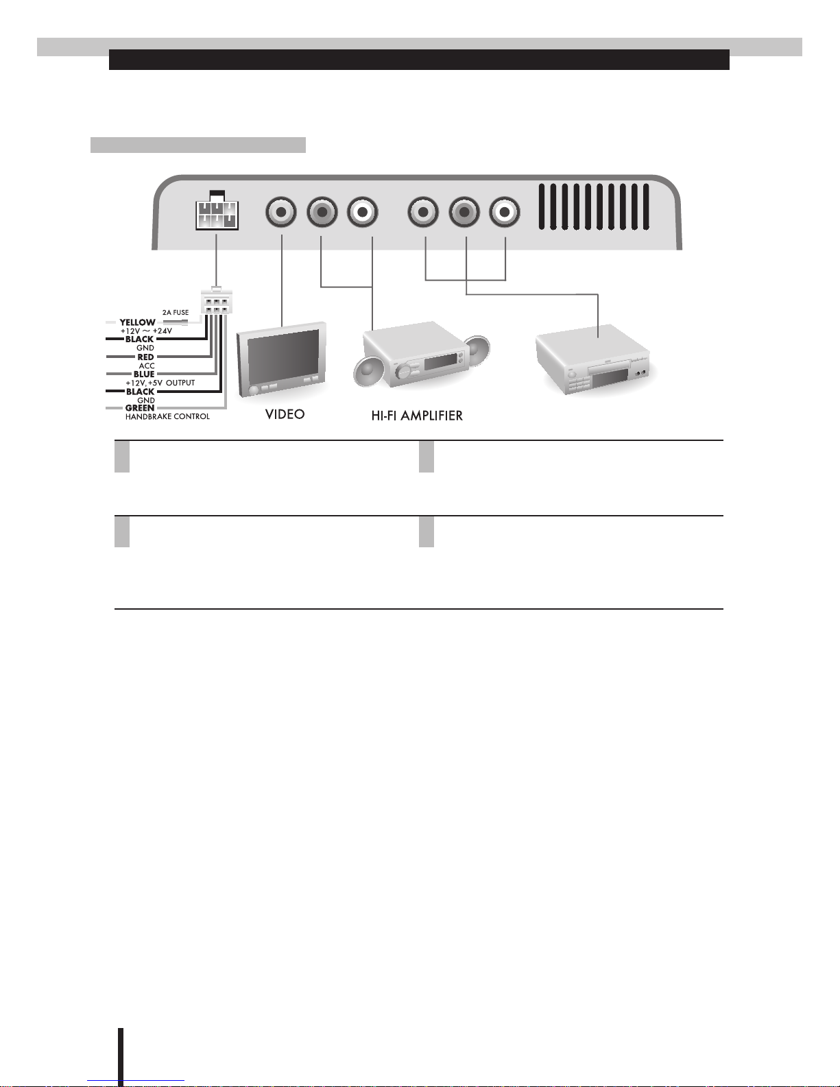
PRODUCT OVERVIEW
Front Panel
DVD/VCD
1.DC IN/SC/ANT-POWER
DC 12V ~ 24V power input, ACC, handbrake
control, power antenna, ground
2.VIDEO OUT
Video output to external LCD screen panel
3.AUDIO OUT L/R
Audio output to external speakers
4.A/V INPUT
Audio & Video input from external devices
such as DVD players, video gaming devices
or camcorders.
①③ ④②
7
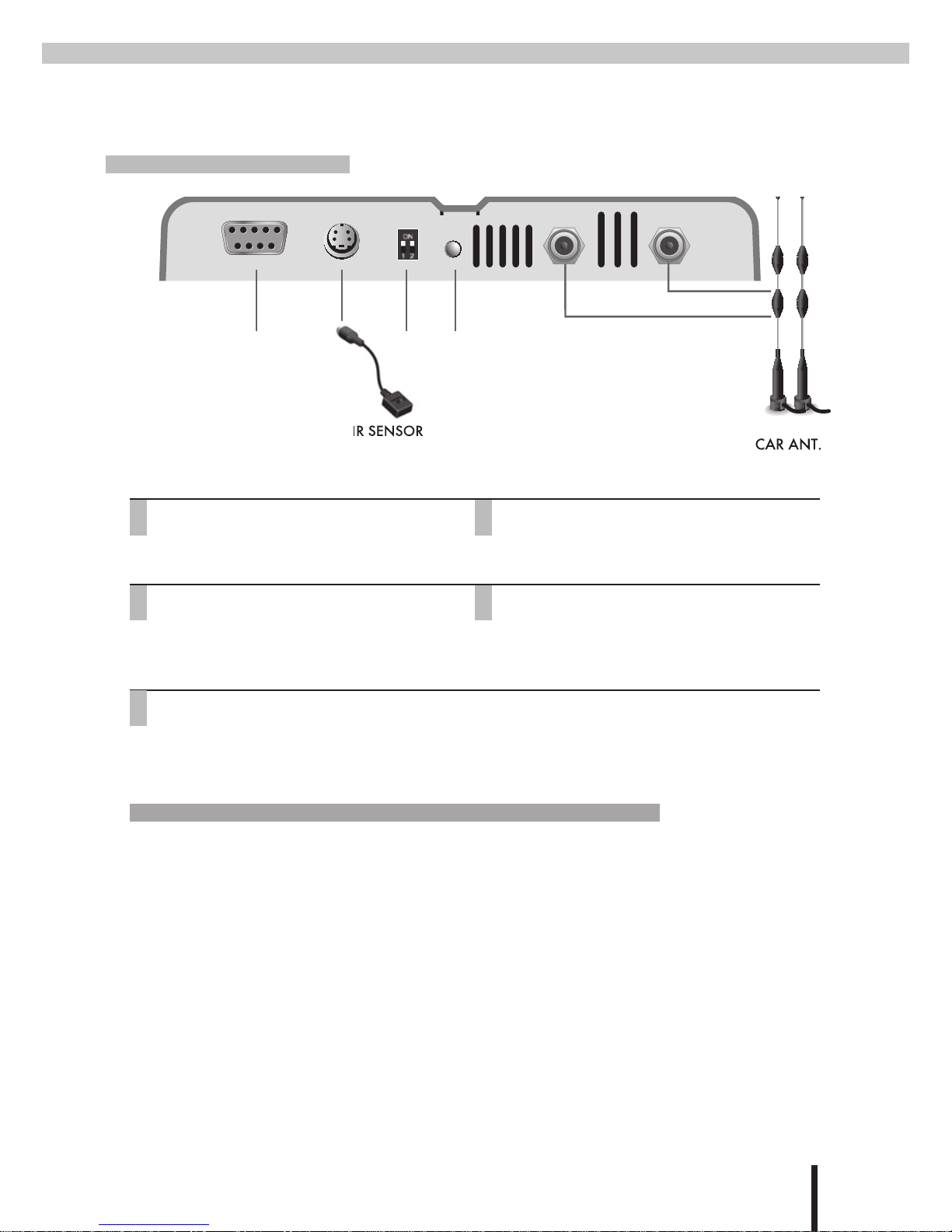
Rear Panel
DVD/VCD
1.RS232
Connects to PC for updating software with
RS232 cable 2 and 3 pin crossed
2.IR IN
Infra-red external cable connector
3.MODE
Viewing mode (On/On), Erase EEPROM (On/
Off), software update (Off/On), PAL/NTSC/
SECAM mode switch (Off/Off)
4.POWER LED
The green light lit indicates power on
5.ANTENNA IN
Connects to digital TV aerial
⊕Mode: 4 different modes. Each mode has a different function.
1 2
on on Viewing mode
on off Erase EEPROM mode (to erase EEPROM software)
a. Press reset button after switching.
b. Wait for screen displays "Erased. Power off"
off on Loader mode (for software upgrade)
a. Press reset button after switching.
b. OSD shows "Loader Invoke mode"
c. Set switch 1 to ON.
d. Update software by "Winupload".
off off Press reset to cycle through the video mode. Each time the reset button is pressed, the
video mode will change from PAL -> NTSC -> SECAM and back to PAL.
① ③ ④
⑤
②
8
Getting Start
Control Panel Usage
Press the•Menu button to display the
control panel.
The default menu displayed will be the•
Channel menu. (The text of the selected
menu will change its colour from white
to yellow).
Use the•Channel menu to preview the
program parameters, to display the signal
status, and to set up a password lock.
While in the•Channel menu, press the
Menu button to enter the Setting menu.
Use the•Setting menu to customize us-
er’s preferences.
While in the•Setting menu, press the
Menu button to enter the Search menu.
Use the•Search menu to select the scan
method and display the signal status.

9
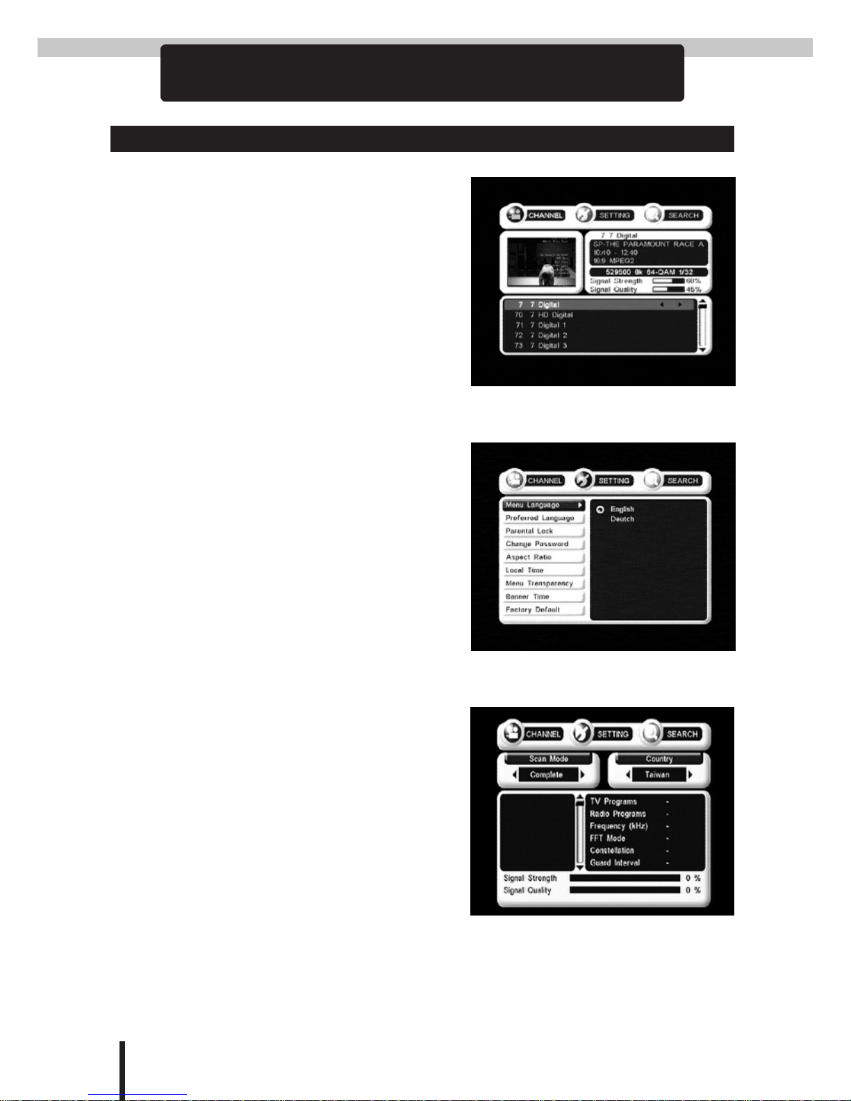
Channel Function Menu
Press the•Menu button to display the
control panel. The default menu dis-
played will be the Channel menu.
The small screen on the left shows the•
program being broadcasted on the chan-
nel that is currently selected in the list
below.
Use the•▲▼ buttons to preview other
channels.
The small screen to the right displays the•
program parameters, the signal strength
and quality.
Signal strength and quality display bar:•
The higher the number and the longer the
bar the better the signal.
At the bottom of the menu display is the•
channel.
Use the• ▲▼ buttons to select a channel.
Use the•◀▶buttons to setup or cancel
locking for the channel.
Enter a user-selected 4-digit password to•
setup or cancel the lock.

10
Setting Function Menu
Controlling the menu:
Press the•Menu button to display the
control panel.
While in the•Channel menu, press the
Menu button to enter the Setting menu.
Use the•▲▼ buttons to select a menu op-
tion (on the left).
Press•OK to enter the sub-menu (on the
right).
Use the• ▲▼ buttons to select an option.
Once selected, press OK to confirm.
Menu Language
Select this menu option to change the•
language displayed in the control panel.
Preferred Language
Select this menu option to change the•
subtitle language.
Change Password
To change the password for the channel•
lock, rst enter the old 4-digit password,
and then enter the password, followed by
the new password again to conrm.
The factory default for the old pass word•
is 0000.
9999 to reset password, if you forgets the•
changed password.
Aspect Ratio
Use this menu option to select the aspect•
ratio that is most suitable for the LCD
screen.

11
Local Time
If the TV program being broadcasted pro-•
vides time information in GMT (Green-
wich Mean Time), then a local GMT
offset must be provided. For example, the
GMT offset for Sydney is +10 hours.
Menu Transparency
Use this menu option to change the trans-•
parency of the menu.
Banner Time
Use this menu option to update the•
amount of time the banner stays visible
when idle.
Factory Default
Press OK twice to reset back to default•
setting
Change TV format
press OK once to go into the factory de-•
fault password option.
Then type 2828 to change the format. The•
system will loop between PAL-NTSC-
SECAM-PAL each time after you do the
steps.
12
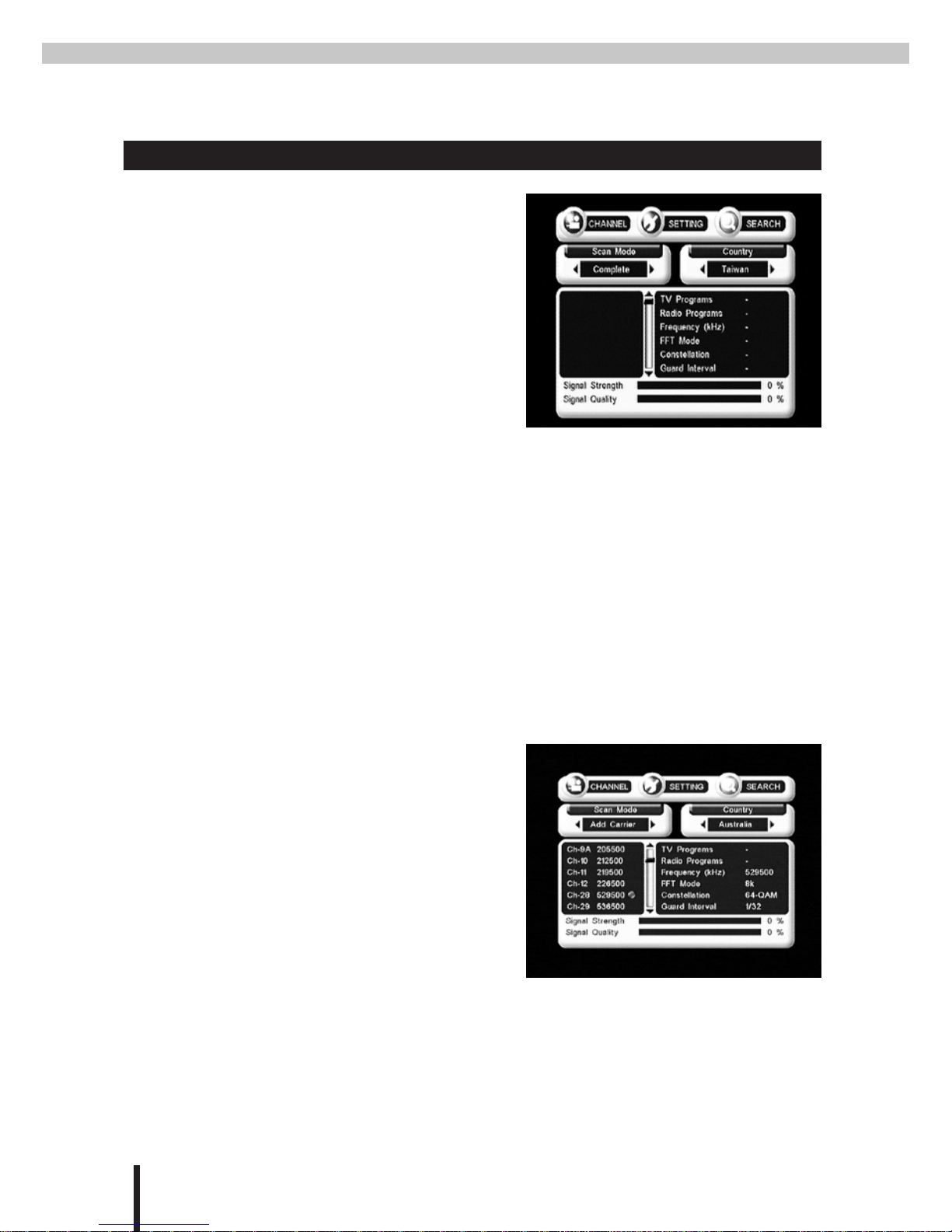
Search Function Menu
Controlling the menu:
Press the•Menu button to display the
control panel.
While in the•Channel menu, press the
Menu button twice to enter the Search
menu.
Use the•◀▶ buttons to select a scan
method.
Press•OK to enter the Country menu option.
Use the•◀▶ buttons to select a country.
Press•OK to confirm.
Use the•▲▼ buttons to select the options inside the carrier window.
Press•OK to confirm.
Press•Exit to leave the menu.
Add a New Carrier
From•Scan Mode select Add Carrier.
Select your country from•Country.
Once the new carrier has been selected in•
the carrier window, press OK to start the
scan.
If signal is received during the scan, the•
statistics window will display details
about the carrier, the signal strength and quality.
After the scan, the carrier window will show a green light to indicate that chan-•
nel is in service. A red light means that the channel is not in service.

13
Delete a Carrier
From•Scan Mode select Delete Car-
rier.
Select your country from•Country.
Select a carrier from the carrier window•
and press OK to delete.
Auto Scan
Fast
From•Scan Mode select Fast.
Once your country has been selected,•
press OK to run the scan (the scan is per-
formed quickly).
Complete
From•Scan Mode select Complete.
Once your country has been selected, press•OK to run the scan (the scan will
runfor a longer period of time).
Edit a Carrier
From•Scan Mode select Edit Carrier.
Select your country from•Country.
Select a carrier from the carrier window•
and press OK to edit.
14
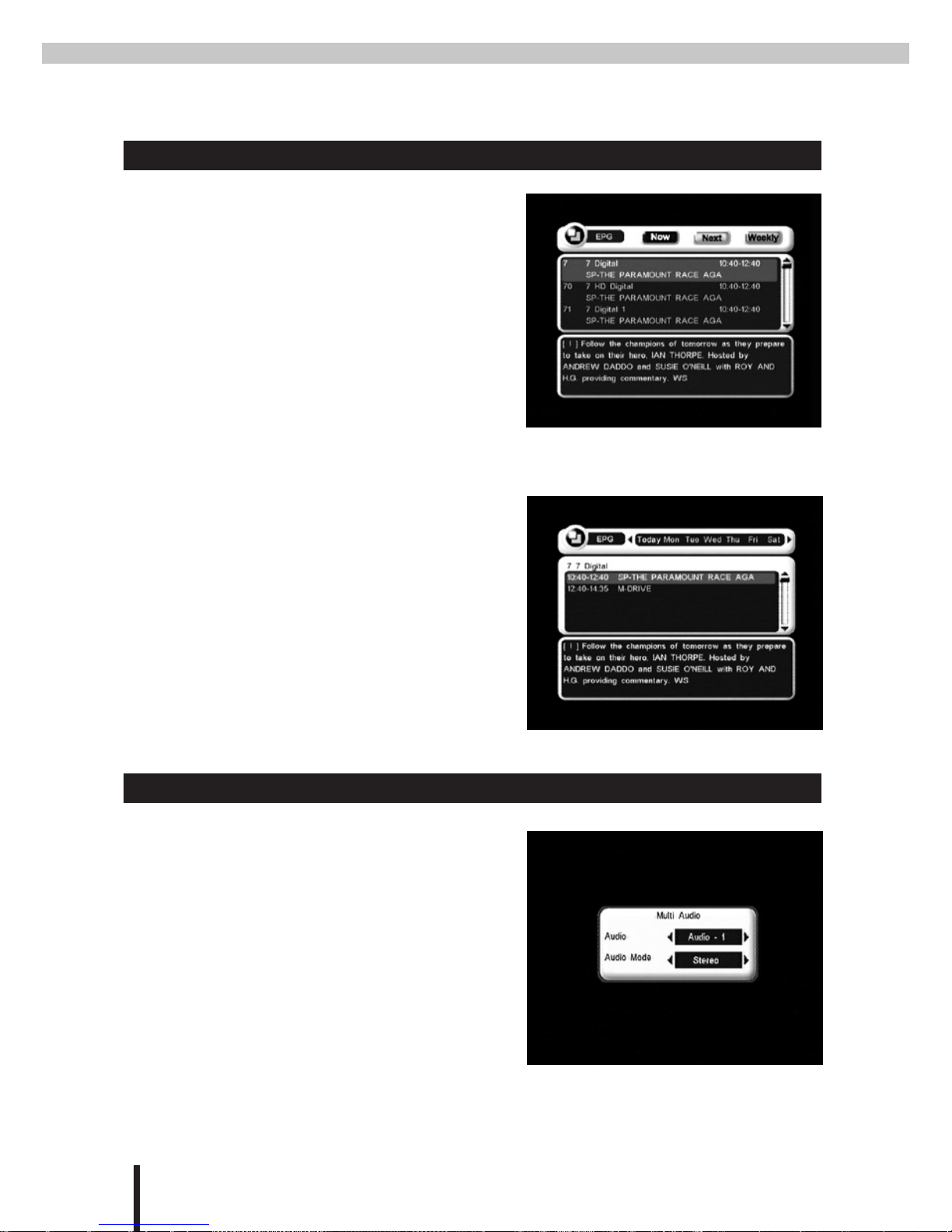
EPG (Electronic Program Guide)
EPG
Press the•EPG button to enter the EPG
window.
Press the buttons (Page+, Page- & Fav+)•
to select the following modes:
NOW(Page+):Program guide for cur-
rently showing programs.
Next(Page-):Program guide for upcom-
ing programs.
Weekly(Fav+):Weekly program guide.
Use the•▲▼ buttons to select a program
to preview.
The lower window displays details of the•
program.
Weekly
While in Weekly EPG mode, the•◀▶
buttons can be used to select a program
for preview.
Multi-channel Audio
Press the•Audio button to enter the mul-
ti-channel audio menu.
Use the•◀▶ buttons the select an audio
channel, which could be Audio-1,2,3...
depending on the source of the signal.
Use the•▲▼ buttons to enter the Audio
Mode option.
Use the•◀▶ buttons to select an audio
Mode, Stereo, Left Channel, Right
Channel or L+R

15
SPECIFICATIONS
Hardware Specications
POWER SUPPLY
Input voltage DC 12V~24V
Power consumption Max. 10W
DEMODULATION
Waveform COFDM
Modes supported 2K & 8K FEC combinations including
hierarchical modes
Constellation QPSK, 16-QAM, and 64-QAM
TUNER
Input connector F Type, Female
Input frequency 170MHz ~ 230MHz (VHF)
470MHz ~ 862MHz (UHF)
Bandwidth 6MHz or 7MHz or 8MHz or 7/8MHz
Front and Rear Summary
FRONT PANEL
DC/SC connector / ANT-
PWR
6 pins wafer for +12V DC/24V DC power
IN/SC handbrake signal, EXT.Power (+5V
or 12V) optional ANT-PWR +5V
Audio 1 RCA/Cinch (Left/Right)
Video 1 RCA/Cinch (75Ω)
A/V Input 1 Pairs RCA
REAR PANEL
Data Port 1 RS232 (9-pin D-sub)
Remote IR connector 4 Pin MINI-DIN
Mode Switch for maintenance purpose (optional)
LED Indicators power / stand-by / system / lock
RF 2 Inputs
GENERAL
INFORMATION
Working temperature 0℃~70℃
Dimension 183 x 144 x 26 mm
Weight 0.6 kg ± 0.05kg
Software Feature
BASIC SYSTEM
MPEG-II Digital & Fully DVB-T Compliant.
LANGUAGES FOR OSD
English / Traditional Chinese/ German/ French/ Spanish/
Italian/ Swedish/ Russian
Manual Channel Search
Supports
Automatic Channel Search
Supports
Upgrade Software
Via RS-232 Loader
PC→Receiver
Teletext
Supports (VBI insertion, OSD teletext)
DVB-Subtitling
Supports
EPG
Supports
MFN
Supports

Table of contents


