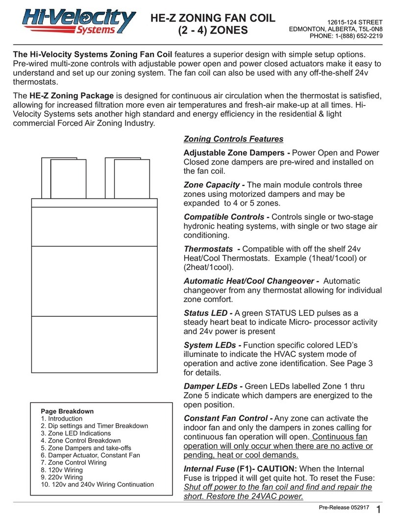
Hi-Velocity HE-Z Series User manual

Manufactured By
Includes:
Hi-Velocity Fan Coils
Heating Coils/Modules
Cooling Coils/Modules
Wiring and WEG Settings
Add-ons and Options
Product Specications
Module-HE-Z-Hi-Velocity-HE-Z-Series-Installation-Manual-051717
HE-Z Series
Installation Manual
Small Duct High Velocity Heating, Cooling and Home Comfort Systems
Features:
• Quiet Operation
• Constant Air Circulation
• Multi-Positional Fan Coil
• Easy Installation & Maintenance
• Space Saving Small Diameter Ducts
• Zoning Capable right out of the Box!
• Many Attractive Vent Plate Options
• Superior Heating, Cooling and IAQ
• Eliminate Hot and Cold Spots

www.hi-velocity.com
© 1995-2017 Energy Saving Products Ltd.
Module INT
Common Parts & Introduction - Pgs. 3-5
Module OTL
Hi-Velocity Outlet Installation - Pgs. 6-7
Locating and Installing Vents, Installing Rough-In Boot
Module FCP
Fan Coil Placement - Pgs. 8-9
Location, Clearances, Hanging Strap Kit
Module DUC
Installing Plenum and Branch Duct - Pgs. 10-18
Location, Connections, Duct Reductions, Flexible Duct
Module
Module
Module RPM
Charging, Heat Pumps, Trouble Shooting
Module
Module
Module
Module
Module
Module SPC

www.hi-velocity.com
© 1995-2017 Energy Saving Products Ltd.
Elbow
Joint Connector
End Cap
Rough-In Boot
Vent Plate
Multi-Positional
Hi-Velocity
Fan Coil
Branch Take-O Plenum Duct
Flexible Duct
Common Parts*
RPM-E Pre-Piped
Cooling Module - Pg. 29
Cooling Options Heating Options
Other Options
HWC Hot Water Coil - Pg. 37
WCM Chilled Water
Module - Pg. 36 ESH Electric Strip
Coil - Pg. 38
Hi-Velocity Air
Purication System
*Example
Conguration
Only
Connection Tee
Module INT
Module INT Introduction to Hi-Velocity (1/3)
WEG Variable
Frequency
Drive - Pg. 22
-3-
Circuit
Board - Pg. 21

www.hi-velocity.com
© 1995-2017 Energy Saving Products Ltd.
optimum result. This manual has been designed to be as concise
Module INT
Module INT Introduction to Hi-Velocity (2/3)
delivery system that can be designed to provide heating, cooling,
a high pressure area to low pressure area, we continuously mix
Because the plenum duct is pressurized, dust build-up within
mold and mildew are reduced.
Primary Applications:
Please read the ENTIRE manual before beginning
installation as this will help avoid mistakes that
may cost time and money.
Hi-Velocity Series Installation Manual
operating costs.
Powered by a variable-speed VFD motor, the Hi-Velocity
Heating Up
Cooling Down
For air conditioning, a cooling module, condensing unit,
chiller, heat pump or geothermal sytem can all be used. The high
the Hi-Velocity System can remove up to 30% more moisture
cooling and ventilation to be installed in applications where the
options are very limited.
Breathing Right
is then used to destroy toxic chemicals and eliminate odours.
to continuously circulate air and ensure even heat distribution.
up to 50 percent.

www.hi-velocity.com
© 1995-2017 Energy Saving Products Ltd.
Module INT
Module INT Introduction to Hi-Velocity (3/3)
Fan coil units shall be a total indoor air quality system complete
changes to, improve upon, or discontinue its products at any
time without public notice or obligation. The descriptions and
printing. Some illustrations may not be applicable to your unit.
IMPORTANT: The Hi-Velocity System is
not to be used for temporary heating
or cooling during the construction of
the structure. If used in this capacity
all warranties will be null and void.
Module SPC - Specications and Sizing
pages please see our website.
• Installation Videos
• Promotional Video
•
•
• Downloadable Installation Modules
•
•
• Complete Parts List
•
• News and Newsletters
• Case Studies
UL Underwriters Laboratories
Terms and Conditions
•
-5-
www.hi-velocity.com
One year limited warranty.
Three year limited warranty.
connections, attachments and other products or materials
This warranty excludes any damages caused by changes,
relocation to, or installation in a new site. This warranty does not
•
part, warranty will not be considered until a contractor
•
•
parts.
•
•
problem. Inoperative parts must be returned in testable
condition.
• This warranty replaces all other warranties expressed or
implied.
Follow these steps for Service or Repair:
1. Contact the installer of the product or a licensed
service company
2. Contact the distributor
3. Contact Energy Saving Products Ltd. Mon-Fri 8
am – 4:30 pm MT 1-888-652-2219

www.hi-velocity.com
© 1995-2017 Energy Saving Products Ltd.
System. Small deviations may be necessary due to existing
construction. However, please contact your system designer
Constant circulation is very important to maintain room
equipped with our optional 15olouvered insert.
Locating Vents
Outlets do not have to be located on an outside wall. Due to the
is gently circulated at all times. The outlets should be located six
Fig. OTL-02 - Six/Seven inches (152mm/178mm) on center
Outlet Installation
PLEASE NOTE:not
applications.
Module OTL
Module OTL Hi-Velocity Outlet Installation (1/2)
Fig. OTL-01 - Cone of Inuence
•
•
• Re-routing the main plenum
avoided. Flexible duct that is run in outside walls may receive a
-6-
6/7”
6/7”
(152/178mm)
(152/178mm)

www.hi-velocity.com
© 1995-2017 Energy Saving Products Ltd.
By locating the vents in this position, there will now be
Fig. OTL-04 - Rough-In Cap Installation
4a
4b - Rough-In Boot installed with a Rough-In Cap
4c - Floor installed Rough-In Boot
4d
Fig. OTL-05 - Trim the edges for kick spaces
Rough-In Caps are used during construction to prevent
damage during construction from drywall dust, saw dust,
stipple ceiling, paint and other small particles from clogging
and damaging the Rough-in Boot and Fan coil unit.
may be necessary to tape the cap on to the Rough-in boot to
hold into place prior to installation. To prevent damage during
construction, do not cut out the Rough-In Caps until the vent
plates are ready to be installed.
spaces without trimming. This can easily be done by trimming
Module OTL
Module OTL Hi-Velocity Outlet Installation (2/2)
Installing the Rough-In Boot
Fig. OTL-03 - Drill a 3” or 3 3/4” (76mm/95mm) hole
Before securing the Rough-In Boot, make sure to use a
Rough-In Cap (Fig. OTL-04).
-7-
(Fig.
OTL-03)
4a 4b
4c
4d

www.hi-velocity.com
© 1995-2017 Energy Saving Products Ltd.
Fig. FCP-03 - Horizontal installation
Table FCP-01 – Fan coil clearances
Unit Inches
Clearances
However, ensure that there is a small space between the unit
Module FCP Hi-Velocity Fan Coil Placement (1/2)
Fig. FCP-02 - Counter ow
-8-
Module FCP
drive permanently lubricated VFD Motor that is mounted within
blower assembly can easily be slid out by removing the three
mounted bolts that attach it to the center plate. In some instances,
the electrical box may need to be removed.
Fan Coil Placement
Location
• Serviceability and access to the unit.
•
•
Fig. FCP-01 - Hi-Boy

www.hi-velocity.com
© 1995-2017 Energy Saving Products Ltd.
Hanging Strap Kit
The Hanging Strap Kits are designed to suspend a horizontal
Reddy Rod or Unistrut.
Hanging Fan Coil Unit Only
installed in a vertical position; they should never be installed at
an angle. It is acceptable to put a 90º twist in the Nylon Straps
Fig. FCP-08 - Install Support if Needed
Fig. FCP-08a - 90° twist
detailed installation instructions.
Fig. FCP-05 - Attach anges to Unit
then into the nylon strap, secure with washer and nut. Repeat
Fig. FCP-06 - Cut Hole in Straps
Fig. FCP-07 - Attach Flanges to all Straps
washer and nut.
Fig. FCP-04 - Hanging Strap Kit Components
BOLT
mm
mm
mm
X8
Fig. FCP-09 Attach Cooling Coil to Fan Coil Unit
Hanging Fan Coil Unit with Cooling Coil
Hanging the
Hi-Velocity Unit
Module FCP
Module FCP Hi-Velocity Fan Coil Placement (2/2)
-9-
X8
X8 X16
X8
FCP-07b
FCP-07a
X
1”

www.hi-velocity.com
© 1995-2017 Energy Saving Products Ltd.
Location
Fig. DUC-01 - Basement Installation
Min. 18” (457mm)
The main plenum can also be easily installed in the attic
Fig. DUC-02 - Attic Installation
18”
(457mm)
the attic are insulated with a vapour barrier.
All A/C systems main plenums need to be
insulated and vapour barriered.
ruling in your area.
vapour barrier. The attic insulation should be placed over all Hi-
Main Plenum Connectors
Hi-Velocity System.
connector, cap, tee, or elbow inside the plenum you intend to
Fig. DUC-03 - Connectors
1. Tee Connection
3. Reducers
5. Straight Connection
Fig. DUC-04 - Alternating screw locations
Figs. DUC-06 and Fig. DUC-07 illustrate a proper install with at
, 8”
OR 10”
Flexible duct is NOT to be used for
supply air plenum.
Plenum Duct
Module DUC
Module DUC Installing Plenum and Branch Duct (1/9)
Insul-Sleeve
over plenum
-10-

www.hi-velocity.com
© 1995-2017 Energy Saving Products Ltd.
in Fig. DUC-05.
Fig. DUC-05 - Sigma Velocity Prole
Uniform
Velocity
Point
10% Loss
20% Loss
30% Loss
Branch Tees
Fig. DUC-06 - Branch Tee, 70/30 split
Bullhead Tees
minimum.
Fig. DUC-08 - Seal all connections
Fig. DUC-09 - Use Metal Strapping
Insulation Sleeve
a vapour barrier. It’s also recommended to vapour barrier runs
Module DUC
Module DUC Installing Plenum and Branch Duct (2/9)
-11-
Fan Coil
30% FLOW
6 Vents
70%
FLOW
14 Vents
EXAMPLE
20 VENTS
18” Min.
Fig. DUC-07 - Bullhead Tee, 50/50 split
Fan Coil EXAMPLE
20 VENTS
50% FLOW
(+/- 10%)
10 Vents
50% FLOW
(+/- 10%)
10 Vents
18” Min.
(457mm)
(457mm)
IMPORTANT!
ENSURE
plenum runs
a minimum of
18” (457mm)
before any
tees, elbows
and take-os.

www.hi-velocity.com
© 1995-2017 Energy Saving Products Ltd.
Fig. DUC-10 - Use an End Cap or Reducer
To install the insulation sleeve over the main plenum, either
Fig. DUC-11 - BTO with insulation sleeve
Connecting Plenum to Fan Coil
together yet, as the plenum may need to be rotated in order
main plenum. Caution must be used when reducing plenum
main plenum. Keep in mind that once reduced, the main plenum
Duct
Size
# of HE
Vents
# of 2”
(51mm)
Vents
Max
Length
4” (102mm) N/A 4 30’ (9.14m)
5” (127mm) 3 6 40’ (12.19m)
6” (152mm) 6 12 50’ (15.24m)
7” (178mm) 9 18 60’ (18.29m)
8” (203mm) 15 30 70’ (21.33m)
10” (254mm) 25 50 100’ (30.48m)
Module DUC
Module DUC Installing Plenum and Branch Duct (3/9)
Table DUC-01 - Duct Reductions

www.hi-velocity.com
© 1995-2017 Energy Saving Products Ltd.
•
•
•
•
•
•
needed.
duct losses on extended runs.
outlet quantities. The HE Duct is designed to directly replace
two (2) standard 2” (51mm) outlets, therefore when an area
requires multiple outlets, a single HE outlet can replace two of
the standard 2” (51mm) ducts. Any combination of 2” (51mm)
ducting, HE ducting, and drilled outlets can be used, following
the minimum and maximum outlets as per unit selection.
Fig. DUC-12 - Drill Hole
Flexible Duct
Duct Size Max CFM Output
TWO
ONE
It is NOT
all holes have been drilled, as it may be necessary to rotate the
plenum to drill the outlets.
Fig. DUC-13a - Branch Take-Off
Fig. DUC-13b - Securing
Module DUC
Module DUC Installing Plenum and Branch Duct (4/9)
Flexible Branch Duct
2” and HE Flex Duct
Tubing Length
10’
0%
15’
10%
35%
-13-

www.hi-velocity.com
© 1995-2017 Energy Saving Products Ltd.
material. Staples may be used, as long as the insulation sleeve
isn’t damaged or torn.
Only use staples if local code allows.
cloth style tapes as they will not create a proper seal. Try to run
Fig. DUC-14 - Use strapping to hold the Flexible duct
Fig. DUC-15 - Through or under joists
Fig. DUC-16a - 2 3/8” holes (60mm)
Fig. DUC-16b - Add insulation at each joist
required. It is recommended to drill the smallest hole possible
with local code laws and ensure that it is allowable to drill holes
volume than usual.
Fig. DUC-17 - 6” (152mm) minimum radius on bends
Module DUC
Module DUC Installing Plenum and Branch Duct (5/9)
Flexible Duct Placement
MIN.
6” or
152mm
BEND
RADIUS (7”
or 178mm
for HE)

www.hi-velocity.com
© 1995-2017 Energy Saving Products Ltd.
duct tape or an approved sealant.
Fig. DUC-18 - Secure to plenum with gentle bends
Hard angles should never be used when connecting to the main
Connecting to Rough-In Boot
The Rough-in Boot can be insulated and vapor barriered using
and vapour barrier in place using a cable tie, tape or other
damperable boot will still turn.
SLIGHT
ANGLE
SLIGHT ANGLE
Fig. DUC-19 - Mechanically Fasten
connect the two branch couplings with the branch connector
barrier with a cable tie. Tighten the cable tie securely around the
branch connector, inner core, insulation, and vapour barrier.
Fig. DUC-20 - Fasten with tie straps
the fully open position.
connections must be taped to ensure a continuous vapour seal.
duct between the insulation and the vapour barrier.
Flexible duct is not to be used in concrete applications.
Caution should be used when running metal or PVC pipe under
concrete, to ensure pipe is not crushed. For certain applications
Unconditioned Spaces
Two Inch Metal Duct
Flexible Duct Termination
Module DUC
Module DUC Installing Plenum and Branch Duct (6/9)
Connecting to the Main Plenum
-15-
Fig. DUC-21 Fig. DUC-22
Connect the vent plate to the connector tube, the other end
Fig. DUC-23 - Extension kit
NOTE: TEST SYSTEM
FOR LEAKS BEFORE
INSTALLATION OF
DRYWALL.
The Flexible Duct coupling is connected to the Rough-In

www.hi-velocity.com
© 1995-2017 Energy Saving Products Ltd.
Fig. DUC-25 - Run ex through opening
3” 76mm
3
”
1”
Fig. DUC-24 - Dimensions
saw, drill a hole where the
vent outlet is to be placed
needs to be enlarged in the
which will allow the Rough-
In Boot to slide easily into
the wall.
Installing 2” Vents in Retrots
the Rough-In Boot to be completely hidden with a beauty ring
Fig. DUC-26 - Trim off the 4 corners
Fig. DUC-27 - Secure ex to Rough-In Boot
Fig. DUC-28 - Feed the ex back into the wall
The Rough-In Boot is placed
Fig. DUC-29 - The Top
Fig. DUC-30 - Pre-drill for anchors
Fig. DUC-31 - Anchors
The vent plate can now be attached to the Rough-In Boot. Be
open position.
Once drywall anchors are installed, screw down the Rough-In
Boot and secure it in place.
Module DUC
Module DUC Installing Plenum and Branch Duct (7/9)
-16-

www.hi-velocity.com
© 1995-2017 Energy Saving Products Ltd.
multiple vents. Multiple vents can be installed into linear grills
Straight
Vane
Fig. DUC-33 - Linear Grills
Linear Grills
Fig. DUC-34 - Straight vanes only
Fig. DUC-36 - Outlet no more than 2” (51mm) from grill
6”/7”
2”
to mix. This will give the room a more even air temperature and
better distribution.
Fig. DUC-35 - 6”/7” Apart on Center (152mm/178mm)
Module DUC
Module DUC Installing Plenum and Branch Duct (8/9)
6”/7”
6”/7”
-17-

www.hi-velocity.com
© 1995-2017 Energy Saving Products Ltd.
with large ceilings the sound can be absorbed by the room or is
Drilled outlets are commonly used to supply a large area with
heating and cooling. Drilled outlets can also be used to create
• 1
• One 1
•
•
plenum the static pressure may drop to an unacceptable
level.
Fig. DUC-37 - 6” (152mm) Apart on center
Plenum Runs on Ceiling
Fig. DUC-38 - Airow 45° angle to oor
Fig. DUC-39 - 6” (152mm) Airow parallel to oor
runs between 0.7”H
allow the static pressure to drop below 0.7”HO
For sidewall installations the outlets are drilled parallel to the
they can be used to create a pressurized air curtain.
Plenum Runs on Sidewall
Drilled Outlets
Module DUC
Module DUC Installing Plenum and Branch Duct (9/9)
-18-

www.hi-velocity.com
© 1995-2017 Energy Saving Products Ltd.
The return air duct is not supplied with the Hi-Velocity System.
It is to be supplied and installed by the contractor. The return air
building code.
Duct Sizing
plus 20%
return ducts that connect to the Hi-Velocity Systems unit.
area to return air.
Return Air
Unit Rigid Ø Flex Ø
Min Sq.
Inches
(Sq. cm)
50/51/52
70/71
100/101
16”
168
Please note: It is VERY important NOT
to undersize the return air, as this will
create noise, increase motor power
consumption and reduce airow.
Module RAI Return Air Installation (1/2)
air with systems that have rooms that are within a common area.
The Hi-Velocity System is a pressure supply duct system that
Fig. RA-01 - Return air cutout
Model Dimensions
9” X 13”
”
Important: When using exible duct for
return air, use one duct size larger due to
the higher friction loss.
-19-

www.hi-velocity.com
© 1995-2017 Energy Saving Products Ltd.
Module RAI Return Air Installation (2/2)
A B C D E
RA-50 1”
181”
1”
1”
1”
RA-70 1”
181”
191”
1”
1”
RA-100 1”
181”
1”
1”
1”
Return Air Base
• Module RPM - Refrigerant Module Installation
• Module WCM - Chilled Water Coil Installation
• Module HWC - Hot Water Coil Installation
• Module ESH - Electric Strip Coil Installation
These manuals are included with the coils, and are also available
online at www.hi-velocity.com.
Once the return air has been cut out, a transition will be needed
Fig. RA-02 – Return Air using a transition
Fig. RA-03 – Hi-Velocity Return Air Base
A
D
C
B
E
Table of contents
Other Hi-Velocity Fan manuals
Popular Fan manuals by other brands
Progress Lighting
Progress Lighting AirPro P2584 installation manual

ClimaRad
ClimaRad Care H1C-C User instructions

Ruck Ventilatoren
Ruck Ventilatoren EMIX EC Series Assembly instruction
Klarstein
Klarstein Storm Tower manual

WAC
WAC BLITZEN F-060 installation instructions
enervent
enervent Neo eWind installation instructions
