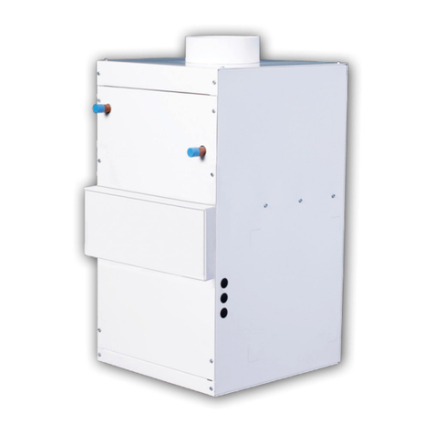
Hi-Velocity HE-Z User manual

The Hi-Velocity Systems Zoning Fan Coil features a superior design with simple setup options.
Pre-wired multi-zone controls with adjustable power open and power closed actuators make it easy to
understand and set up our zoning system. The fan coil can also be used with any off-the-shelf 24v
thermostats.
The HE-Z Zoning Package is designed for continuous air circulation when the thermostat is satisfied,
allowing for increased filtration more even air temperatures and fresh-air make-up at all times. Hi-
Velocity Systems sets another high standard and energy efficiency in the residential & light
commercial Forced Air Zoning Industry.
Zoning Controls Features
Adjustable Zone Dampers - Power Open and Power
Closed zone dampers are pre-wired and installed on
the fan coil.
Zone Capacity - The main module controls three
zones using motorized dampers and may be
expanded to 4 or 5 zones.
Compatible Controls - Controls single or two-stage
hydronic heating systems, with single or two stage air
conditioning.
Thermostats - Compatible with off the shelf 24v
Heat/Cool Thermostats. Example (1heat/1cool) or
(2heat/1cool).
Automatic Heat/Cool Changeover - Automatic
changeover from any thermostat allowing for individual
zone comfort.
Status LED - A green STATUS LED pulses as a
steady heart beat to indicate Micro- processor activity
and 24v power is present
System LEDs - Function specific colored LED’s
illuminate to indicate the HVAC system mode of
operation and active zone identification.
Damper LEDs - Green LEDs labelled Zone 1 thru
Zone 5 indicate which dampers are energized to the
open position.
See Page 3
for details.
Constant Fan Control - Any zone can activate the
indoor fan and only the dampers in zones calling for
continuous fan operation will open. Continuous fan
operation will only occur when there are no active or
pending, heat or cool demands.
Internal Fuse (F1)- CAUTION: When the Internal
Fuse is tripped it will get quite hot. To reset the Fuse:
Shut off power to the fan coil and find and repair the
short. Restore the 24VAC power.
Page Breakdown
1. Introduction
2. Dip settings and Timer Breakdown
3. Zone LED Indications
4. Zone Control Breakdown
5. Zone Dampers and take-offs
6. Damper Actuator, Constant Fan
7. Zone Control Wiring
8. 120v Wiring
9. 220v Wiring
10. 120v and 240v Wiring Continuation
1
12615-124 STREET
EDMONTON, ALBERTA, T5L-0N8
PHONE: 1-(888) 652-2219
HE-Z ZONING FAN COIL
(2 - 4) ZONES
Pre-Release 052917

Selecting the Options Using the DIP Switches
Select OAS, if you
want to delay auxiliary heat based on the
outside air temperature sensor. Select TIMER, if
you want to delay staging heat & cool based on
the adjustable on-board timer. NOTE: ‘Y2’ output
defaults to a 30 minute delay, when OAS is
chosen. An optional Outside Air Sensor (OAS) is
required to use the OAS feature.
Select OFF, if you do
not want to inhibit Y2 and/or auxiliary heat
based on the total number of zones calling.
Select ON, if you want to inhibit Y2 and/or
auxiliary heat based on the total number of
zones calling. More than half the total zones
must be calling for the same mode of operation
(heat or cool), or the zone panel will not stage
up. The 50% rule will always dominate the
staging timer and thermostat demands unless
Emergency mode is active.
Select OFF, if you do not
want to use the supply air sensor for the Zone
Control system. Select ON, if you intend to use
an optional supply air sensor (SAS).
NOTE: The indoor
fan mode is automatically set for you. There is
no need to move this switch when setting up for
operations.
OAS < STAGING > TIMER -
OFF < 50% RULE > ON -
Seven Built-in Timers for Safe & Reliable
Operation
** During set-up momentarily pressing the
RESET Button clears the built-in timers.
Pressing the RESET Button for 7 seconds will
reset the CPU.
Startup Delay Timer - The panel will not
activate any cooling or heating operation until
the startup delay has expired.Momentarily
pressing the RESET Button clears the built-in
OFF < SAS > ON -
GAS < FAN > HYDRONIC -
* Start-up Delay Timer = 3 minutes-fixed
* Short Cycle Timer = 3 minutes-fixed
* Change Over Timer = 4 minutes-fixed
* Opposing Call Timer = 20 minutes-fixed
* Staging Timer = OFF or 7-42 min.-Adj.
* Supply Air Limit Timer = 3 minutes-fixed
* Purge Delay Timer = 90 seconds-fixed
Programming and Setting up your HVAC
System
Review each pin setting explanation of each dip
switch function and choose your settings for
correct operations. Some functions may not
apply to your application.
** Push the reset button for 7 seconds whenever
there is a change the dip settings to reset the
CPU.
O < RV > B -
HP < SYSTEM > OTHER -
DF < HP > CONV -
HC < TSTATS > HP -
IMPORTANT NOTE: True thermostatic
staging is not available when using 2 Stage
compressors, it is advisable to use single stage
Heat/Cool or HP thermostats and allow the zone
panel to stage via the on-board timer.
Type of HVAC
system you want to control. Select HP, if your
system is any type of Heat Pump. Select
OTHER, if your system is Hydronic/Electric
and/or Standard Cooling.
If HP is selected type of
Heat Pump you want to control. Select DF
(Restricted Mode) locks out the compressor
during auxiliary heat operation. Select CONV
(Unrestricted Mode) if you wish to have the
compressor run during auxiliary heat operations.
Select HC for regular
Heat/Cool thermostats, select HP for Heat
Pumps.
Select the correct Reversing
Valve signal for your particular Heat Pump.
Choose “O” for any Heat Pump that energizes
the RV in the cooling mode. Choose “B” for any
Heat Pump that energizes the RV in heating
mode.
1
2
3
4
5
6
7
8
1
2
3
4
5
6
7
8
ON
HP < SYSTEM > OTHER
DF < HP > CONV
HC < TSTATS > HP
O < RV > B
OAS < STAGING > TIMER
OFF < 50% RULE > ON
OFF < SAS > ON
GAS < FAN > HYDRONIC
DEFAULT
OTHER
CONV
HC
O
TIMER
OFF
OFF
GAS
2
052917Pre-Release 052917

Zoning Panel LED’s
The 11 function specific LED’s that indicate HVAC system operation and zone damper status.
Familiarize yourself with the LED functions and definitions, in order to accurately determine the Zoned
HVAC system status and mode of operation.
3
Continue: Seven Built-in Timers
timers This occurs after any initial power up or
power failure. Press the Reset button for 1
second to override.
Short Cycle Timer - When all zone demands
are satisfied, the panel will not resume the same
mode of operation for a minimum of 3 minutes.
Changeover Timer - Prevents the system from
rapidly switching between heating and cooling
modes. At the end of a call, a 4 minute timer is
started and the panel will not switch to the
opposing mode until the timer has expired.
Opposing Call Delay - A 20 minute delay must
expire, or the active zone(s) must satisfy, before
the panel will honor a demand to changeover to
the opposite mode of system operation.
Staging Timer/OAS - The STAGING TIMER
sets the amount of continuous call time in 1st
stage, before second stage heat or cool is
energized. NOTE: The potentiometer also
serves as the Outside Air Changeover Setting.
Purge Delay - The STAGING TIMER sets the
amount of continuous call time in 1st stage,
before second stage heat or cool is energized.
NOTE: The potentiometer also serves as the
Outside Air Changeover Setting
The STATUS LED pulses as a steady
heart beat to indicate proper Micro-
processor system status.
The OAS LED illuminates solid to
indicate that the Outdoor Temperature
has fallen below the chosen set point.
The OAS LED will blink rapidly to
indicate a shorted or open Outdoor Air
Sensor circuit.
The SAS LED illuminates solid to
indicate that the Supply Temperature
has exceeded the chosen set point on
either the HIGH TEMP LIMIT or the
LOW TEMP LIMIT. The SAS LED will
blink rapidly to indicate a shorted or
open Supply Air Sensor circuit.
The ZONE 3 LED: Indicates that
damper(s) is energized open, and the
Zone is active.
The ZONE 2 LED: Indicates that
damper(s) is energized open, and the
Zone is active.
The ZONE 1 LED: Indicates that
damper(s) is energized open, and the
Zone is active.
STATUS
GREEN
ZONE 1
GREEN
ZONE 2
GREEN
ZONE 3
GREEN
SAS
RED
OAS
RED
The FAN LED: Indicates a demand for
fan operation, during COOLING,
HEATING, PURGE, or CONTINUOUS
FAN operations.
The Y2 LED: Indicates the 2nd stage of
DX COOLING or DX HEATING is
energized.
The Y1 LED: Indicates the 1ST stage of
DX COOLING or DX HEATING is
energized.
The W1/B LED: Indicates that the 1st
stage of HEATING is energized in
Gas/Hydronic mode. The W1/B LED
also ‘B’ reversing
valve is energized in HEAT PUMP
operation. NOTE: In Heat Pump Operation,
this LED will stay illuminated after the call for
heat is completed.
The W2/E LED: Indicates 2nd or 3rd
stage of HEATING is energized in
GAS/HYDRONIC or HEAT PUMP
mode. The W2/E LED also
EMERGENCY HEAT is energized
in HEAT PUMP mode.
illuminates when
illuminates
when
W1/B
RED
FAN
GREEN
Y1
YELLOW
Y2
YELLOW
W2/E
RED
052917Pre-Release 052917

Zone Controller Breakdown
4
R
G
Y
O/B
W/E
C
R
G
Y
O/B
W/E
C
T’
S
T
A
T
T’
S
T
A
T
M1
M4
M6
M2
D
A
M
P
E
R
M1
M4
M6
M2
D
A
M
P
E
R
STATUS
J1
XM2
rev B
M1
M4
M6
M2
D
A
M
P
E
R
M1
M4
M6
M2
D
A
M
P
E
R
J1
A [ 0 - 1 ]
A [ 0 - 2 ]
R
G
Y
O/B
W/E
C
R
G
Y
O/B
W/E
C
T’
S
T
A
T
T’
S
T
A
T
Z
O
N
E
5
Z
O
N
E
4
RESET
+
+
F1
OAS
SAS
SAS
OAS
M1
M4
M6
M2
ZONE 3
MOTOR
M1
M4
M6
M2
ZONE 2
MOTOR
M1
M4
M6
M2
ZONE 1
MOTOR
C
R
24 VAC
T’FORMER
C
R
SYSTEM
W2/E
Y1
Y2
RH
RC
G
W1/B
C
O
RC / RH
LINK
OAS
LED 2
Y
C
W
R
G
O/B
ONE
ZONE
Y
C
W
R
G
O/B
ZONE 2
T’STAT
ZONE1
T’STAT
Y
C
W
R
G
O/B
ZONE 3
T’STAT
STATUS
LED 1
SAS
LED 3
ZONE 3
LED 4
FAN
LED 7
Y2
LED 8
ZONE 1
LED 6
ZONE 2
LED 5
W1 / B
LED 10
Y1
LED 9
W2 / EM
LED 11
2
R
3
R
4
R
2ND STAGE HEAT
DIFFERENTIAL
47
5
40
33
26
19
12
HIGH TEMP
LIMIT
110
120
130 140 150
160
170
LOW TEMP
LIMIT
52
49
46
43
40
37
34
FUTURE USAGE
J1
TIMER OAS
STAGING
42
35
28
21
14
7
OFF
R
1
NORM
EM
Y
C
W
R
G
O/B
ONE
ZONE
EMERGENCY
HEAT SWITCH
GAS < FAN > HYDRONIC
OFF < SAS > ON
OFF < 50% RULE > ON
OAS < STAGING > TIMER
HC < TSTATS > HP
HP < SYSTEM > OTHER
DF < SYSTEM > CONV
TIMER OAS
STAGING
42
35
28
21
14
7
OFF
R
1
OFF, 7 - 42 minutes or
7 - 42 degrees F.
Any Setting below 7 is OFF!
OFF,
DO NOT set to - OFF - when using OAS
Emergency
Heat Switch
Isolated
HVAC System
Terminal Block
Future Supply Air and
Outdoor Air Sensor
Connections
24v 4.0 amp
Fuse
STAGING TIMER (W2/E AND Y2 OUTPUT)
DIP switch settings for
1st Expansion panel.
Zones 4 & 5
To Line
Voltage
Optional 24 VAC
Transformer
Pressing the RESET Button for 7 seconds
will reset the CPU for the entire zone system
Reset the CPU anytime you change the dip
switch settings.
Momentarily pressing the RESET Button
clears the built-in timers, this enables you to
test the installation faster. The built-in timers
controls the:
- Start-up delay timer
- Short cycle timer
- W2 timer
- Staging timer
- Changeover timer.
** Caution should be observed when using
this button.
Expansion Zone
Control for 4 - 5
Zones **
Main Zone
Controller
** Expansion Zone Control is installed in 4
zones unit only
Power and data
polarized Bus
Cable
052917Pre-Release 052917
O < RV > B

FRONT
2 - 8"
Zone
1
Zone
2
FRONT
2 - 8", 1 - 6"
Zone
1
Zone
2
Zone
3
FRONT
4 - 6"
Zone
1
Zone
2
Zone
3
Zone
4
FRONT
3 - 8"
Zone
1
Zone
2
Zone
3
FRONT
4 - 8"
Zone
1
Zone
2
Zone
3
Zone
4
FRONT
2 - 8"
Zone
1
Zone
2
FRONT
4 - 6"
Zone
1
Zone
2
Zone
3
Zone
4
FRONT
2 - 8", 1 - 6"
Zone
1
Zone
2
Zone
3
Zone
2Zone
1
Zone
4
Zone
3
FRONT
ZONE DAMPER LOCATIONS AND PLENUM TAKE-OFF SIZES
5
HE-Z-100-(**)-(***V)
c/w
** = BU (Blower Unit or
H c/w Hot Water Coil)
*** = 110v or 220v
HE-Z-100-Z4
10"
6"
8"
Zone Plenum Sizes
052917
HE-Z Zone Package Add-Ons - 2, 3 or 4 Collars
The Zoning Add-On package includes pre-wired zone panel and 2, 3 or 4 collars, each w/ power
open/close dampers and actuators installed. These are currently available pre-installed on our HE-Z
Series Fan Coils. Order HE-Z fan coil unit from our Standard Price List and add these multi-outlet
tops to your order as a separate part.
The plenum take-off outlets are 7" in height and adds to the height of the 32" fan coil. The fan coil can
be installed in the high boy, counter flow or horizontal position. When you are designing the individual
zones try to design each zone to have equal amount of vents and load.
Pre-Release 052917
HE-Z-50-Z2 HE-Z-50-Z4HE-Z-50-Z3
HE-Z-70-Z2
FRONT
2 - 10"
Zone
1
Zone
2
HE-Z-100-Z2
HE-Z-70-Z3 HE-Z-70-Z4
HE-Z-100-Z3 HE-Z-100-Z4

F.000
Open and Closed Adjustment Stops
The Adjustment Stops can be
adjusted to stop rotating before it
reaches its stops. These can be
moved to any position without harm.
1. Loosen the end stops. Caution: be
cautious not to unscrew from the
captive nut under the slot.
2. Move the stops (2.5° steps) to the
desired position and re-tighten the
screw.
Manual Override Button
Press the Manual Override Button
and the gear train is dis-engaged so
the damper shaft can be moved
manually. Release the button and the
gear train is re-engaged.
To lock in manual mode press down
the Manual Override Button and push
in the side locking tab. To release,
push down the Manual Override
Button and release this will disengage
lock.
0 1
0
1
Manual Override
Button
1
-~
+
2~
3+
Closing and Opening
Adjustment Stops
M6 - 24vac Closes damper
M4 - 24vac Opens damper
M2 - Constant 24 vac HOT
M1 - Common 24 vac
ZONE DAMPER WIRING
M6
M4
M2
M1
3
2
1
Constant Fan Comfort
Having the fan switch at the thermostat to the
“ON” position is strongly recommended. This
utilizes continuous air circulation for optimal
Indoor Air Quality (IAQ) and Energy Efficiency.
Independent testing has shown that utilizing the
recirculating fan with the Hi-Velocity Systems
VFD motor reduces total energy usage. This is
due to less on/off cycling of AC and Heating
equipment by constant de-stratification of the air.
The zone controller board will default the
actuators in the open position when there is no
call for constant fan, heat or cooling. If one of the
zones is calling for constant fan and the others
are not, the zones that are not calling will close.
In the event of a zone calling for heat or cooling
the zone dampers (regardless if a zone is calling
for constant fan) will close the non-calling
heat/cool zones. The actuators have been pre-
adjusted with approximately 10% bleed through,
this allows for air to circulate in a non-calling
zone. With the 10% by-pass it will not over heat
or cool a non-calling zone if the other zones are
calling heat or cooling but will add comfort as the
air will not be stagnate in the non-calling zone
and will supply more even air temperatures
throughout.
Zone Dampers Adjustment Stops
The Adjustment Stops on the
actuators have been preadjusted with
approximately 10% bleed through.
This allows for air to circulate in a
non-calling zone. This can be
adjusted by adjusting the “0" stop
limit.
Balancing Zones
In the case that there is too much
pressure through a calling zone
(usually a smaller zone on the
system) the damper can be adjusted
partially closed. Partially closing a
damper will cause back pressure on
the blowers pressure control and the
fan coil will slow down the motor.
Adjust the “1" stop to limit the
actuators opening to the level of
pressure/air required for the air flow
desired for the smaller zone.
Zone damper Wiring
The zone dampers on the HE-Z
Zoning Fan Coil comes pre-wired.
There are Seven Built-in Timers that
over ride the operation of the zone
dampers and output signals of the
zone board these are shown on
pages 2 and 3.
Damper Adjustment
6
052917Pre-Release 052917

Damper Wiring and Configuration
Y1
W1
C
G
W2
O/B
D
R
Y2
ZONE 3
THERMOSTAT
G
R
O/B
Y
W/E
C
C
W
Y
R
G
O/B
ZONE 3 THERMOSTAT INPUT
ZONE 2
THERMOSTAT
G
R
O/B
Y
W/E
C
C
W
Y
R
G
O/B
ZONE 2 THERMOSTAT INPUT
32 1
M6
M4
M2
M1
ZONE 2
DAMPER
32 1
M6
M4
M2
M1
ZONE 3
DAMPER
32 1
M6
M4
M2
M1
ZONE 1
DAMPER
24V INPUT - 4.0A
PROTECTED
R
C
G
Y2
Y1
O
W1/B
W2/E
RH
RC
C
ZONE 1
THERMOSTAT
C
W
Y
R
G
O/B
ZONE 1 THERMOSTAT INPUT
G
R
O/B
Y
W/E
C
ONE
ZONE
Y1
1
RH
RC
R
C
1OPTIONAL EXTERNAL 24V
1. REMOVE THE R AND C JUMPER
AND REPLACE WITH THE OPTIONAL
EXTERNAL 24V TRANSFORMER
HVAC
SYSTEM
HI-VELOCITY
PSB CIRCUIT BOARD
7
052917
SINGLE STAGE CONDENSING UNIT
TWO STAGE OR VARIABLE SPEED CONDENSING UNIT
Y1
W1
C
G
W2
O/B
D
R
Y2
ZONE 3
THERMOSTAT
G
R
O/B
Y
W/E
C
C
W
Y
R
G
O/B
ZONE 3 THERMOSTAT INPUT
ZONE 2
THERMOSTAT
G
R
O/B
Y
W/E
C
C
W
Y
R
G
O/B
ZONE 2 THERMOSTAT INPUT
32 1
M6
M4
M2
M1
ZONE 2
DAMPER
32 1
M6
M4
M2
M1
ZONE 3
DAMPER
32 1
M6
M4
M2
M1
ZONE 1
DAMPER
24V INPUT - 4.0A
PROTECTED
R
C
R
C
G
Y2
Y1
O
W1/B
W2/E
RH
RC
C
ZONE 1
THERMOSTAT
C
W
Y
R
G
O/B
ZONE 1 THERMOSTAT INPUT
G
R
O/B
Y
W/E
C
ONE
ZONE
HVAC
SYSTEM
HI-VELOCITY
PSB CIRCUIT BOARD
Dampers default to the "OPEN" position
- After a purge delay
- During change over
- Short cycle delays
- When all zone demands are satisfied with
no signals from the thermostats.
From factory the fan coil is pre-wired for two
stage cooling. If single stage cooling is desired
the fan coils controls will need to be re-wired.
Below are the required changes.
Follow the HE-Z Fan coils main Installation
Manual for wiring the PSB to the system.
RH and RC is
internally jumpered.
1OPTIONAL EXTERNAL 24V
1. REMOVE THE R AND C JUMPER
AND REPLACE WITH THE OPTIONAL
EXTERNAL 24V TRANSFORMER
RH and RC is
internally jumpered.
1
Pre-Release 052917

8
052917Pre-Release 052917
PSB / VFD POWER INPUT: 110-127/1/50-60
052917
HE-Z ZONING
120V
RESET
+
+
F1
OAS
SAS
SAS
OAS
M1
M4
M6
M2
ZONE 3
MOTOR
M1
M4
M6
M2
ZONE 2
MOTOR
M1
M4
M6
M2
ZONE 1
MOTOR
C
R
24 VAC
T’FORMER
C
R
SYSTEM
W2/E
Y1
Y2
RH
RC
G
W1/B
C
O
RC / RH
LINK
OAS
LED 2
Y
C
W
R
G
O/B
ONE
ZONE
Y
C
W
R
G
O/B
ZONE 2
T’STAT
ZONE1
T’STAT
Y
C
W
R
G
O/B
ZONE 3
T’STAT
STATUS
LED 1
SAS
LED 3
ZONE 3
LED 4
FAN
LED 7
Y2
LED 8
ZONE 1
LED 6
ZONE 2
LED 5
W1 / B
LED 10
Y1
LED 9
W2 / EM
LED 11
2
R
3
R
4
R
2ND STAGE HEAT
DIFFERENTIAL
47
5
40
33
26
19
12
HIGH TEMP
LIMIT
110
120
130 140 150
160
170
LOW TEMP
LIMIT
52
49
46
43
40
37
34
FUTURE USAGE
J1
TIMER OAS
STAGING
42
35
28
21
14
7
OFF
R
1
NORM
EM
Y
C
W
R
G
O/B
ONE
ZONE
EMERGENCY
HEAT SWITCH
R
G
Y
O/B
W/E
C
R
G
Y
O/B
W/E
C
T’
S
T
A
T
T’
S
T
A
T
M1
M4
M6
M2
M1
M4
M6
M2
D
A
M
P
STATUS
J1J1
A [ 0 - 1 ]
A [ 0 - 2 ]
R
G
Y
O/B
W/E
C
R
G
Y
O/B
W/E
C
T’
S
T
A
T
T’
S
T
A
T
Z
O
N
E
5
Z
O
N
E
4
D
A
M
P
4
D
A
M
P
4
4
3
2
1
3
2
1
3
2
1
3
2
1
Expansion Zone Control
SUPPLIED WITH 4 ZONE OPTION ONLY
Zone Control
ZONE 4
DAMPER
ZONE 2
DAMPER
3
2
1
3
2
1
ZONE 3
DAMPER
ZONE 1
DAMPER
ZONE 4
MOTOR
O < RV > B
GAS < FAN > HYDRONIC
OFF < SAS > ON
OFF < 50% RULE > ON
OAS < STAGING > TIMER
HC < TSTATS > HP
HP < SYSTEM > OTHER
DF < SYSTEM > CONV
1 2 3 4 5 6 7 8 9 10 11 12
L/L1 N/L2 U V W PE
P
0
I
Parameter
Value
WEG CONTROLLER
VFD
110-120 VAC
W1
W2
CRY2 Y1 DO/B
G
R
Y1 W2 W1 FZ FZ
Y2
C
F1
AUXILIARY RELAY
(HEATING)
L L
L2L2 NL1 L1
A3 A2 A1
LN
COOL HEAT FAN
LED
L1
J8
ON
OFF
H2
TIMER
AUTO
MAN
H3
MODE
ON
OFF
H4
DELAY
J5
J7
J4
U2
J3
R8
R7
R6
G C H F
318.29 Pcbw-001sep-040
J2
N
C
Ri
Ro
H1
J9
J1
LED
L2
PSB CIRCUIT BOARD
24v OUTPUTEMERGENCY DISCONNECT
C
110-127 VAC
110-127/1/50-60
110-127v POWER CABLE
L
N
Ground
WH
BK
G
LINE IN
EMERGENCY DISCONNECT
C - 24 VAC COMMON
C - 24 VAC COMMON
Ro - 24 VAC OUTPUT
Ri - 24 VAC INPUT
AUXILIARY HEATING RELAY
N - NEUTRAL
L - LINE VOLTAGE
A1 - AUXILIARY NORMALLY OPEN
A2 - AUXILIARY NORMALLY CLOSED
A3 - AUXILIARY COMMON
24 VAC OUTPUT CONNECTIONS
FZ - FREEZE STAT
FZ - FREEZE STAT
W1 - HEATING (W1) 24 VAC OUTPUT
W2 - HEATING (W2) 24 VAC OUTPUT
Y2 - CONDENSING UNIT 24 VAC OUTPUT
Y1 - CONDENSING UNIT 24 VAC OUTPUT
C - 24 VAC COMMON
R - 24 VAC OUTPUT
THERMOSTAT CONNECTIONS
R - 24 VAC OUTPUT
W1 - FIRST STAGE HEAT
W2 - SECOND STAGE HEAT
(OR SINGLE STAGE)
Y1 - FIRST STAGE COOLING
Y2 - SECOND STAGE COOLING
(OR SINGLE STAGE)
C - 24 VAC COMMON
G - THERMOSTAT FAN SWITCH
D - PRIORITY (RUNS AT W SPEED)
O/B - HEATPUMP REVERSING
MOTOR LEADS PLUG
(3 PHASE)
CAUTION
FOR SINGLE STAGE
COOLING OPERATION
USE Y2 OTHERWISE THE
FREEZE STAT WILL BE
BYPASSED
CAUTION
FOR SINGLE STAGE
COOLING OPERATION
USE Y2 OTHERWISE THE
FREEZE STAT WILL BE
BYPASSED
Equipment
Ground
TRIM POTS (COOLING, HEATING, CONSTANT FAN)
- ATMOSPHERIC PRESSURE
+ DUCT PRESSURE
TRIM POTS (COOLING, HEATING, CONSTANT FAN)
- ATMOSPHERIC PRESSURE
+ DUCT PRESSURE
24v / 20va
TRANSFORMER
Black
White
Orange
Black
Orange
White
Red
Red
Black
Black Wire (-)
+
-
Red Wire (+)
0-10 VDC
Equipment
Ground

RESET
+
+
F1
OAS
SAS
SAS
OAS
M1
M4
M6
M2
ZONE 3
MOTOR
M1
M4
M6
M2
ZONE 2
MOTOR
M1
M4
M6
M2
ZONE 1
MOTOR
C
R
24 VAC
T’FORMER
C
R
SYSTEM
W2/E
Y1
Y2
RH
RC
G
W1/B
C
O
RC / RH
LINK
OAS
LED 2
Y
C
W
R
G
O/B
ONE
ZONE
Y
C
W
R
G
O/B
ZONE 2
T’STAT
ZONE1
T’STAT
Y
C
W
R
G
O/B
ZONE 3
T’STAT
STATUS
LED 1
SAS
LED 3
ZONE 3
LED 4
FAN
LED 7
Y2
LED 8
ZONE 1
LED 6
ZONE 2
LED 5
W1 / B
LED 10
Y1
LED 9
W2 / EM
LED 11
2
R
3
R
4
R
2ND STAGE HEAT
DIFFERENTIAL
47
5
40
33
26
19
12
HIGH TEMP
LIMIT
110
120
130 140 150
160
170
LOW TEMP
LIMIT
52
49
46
43
40
37
34
FUTURE USAGE
J1
TIMER OAS
STAGING
42
35
28
21
14
7
OFF
R
1
NORM
EM
Y
C
W
R
G
O/B
ONE
ZONE
EMERGENCY
HEAT SWITCH
R
G
Y
O/B
W/E
C
R
G
Y
O/B
W/E
C
T’
S
T
A
T
T’
S
T
A
T
M1
M4
M6
M2
M1
M4
M6
M2
D
A
M
P
STATUS
J1J1
A [ 0 - 1 ]
A [ 0 - 2 ]
R
G
Y
O/B
W/E
C
R
G
Y
O/B
W/E
C
T’
S
T
A
T
T’
S
T
A
T
Z
O
N
E
5
Z
O
N
E
4
D
A
M
P
4
D
A
M
P
4
4
3
2
1
3
2
1
3
2
1
3
2
1
Expansion Zone Control
SUPPLIED WITH 4 ZONE OPTION ONLY
Zone Control
ZONE 4
DAMPER
ZONE 2
DAMPER
3
2
1
3
2
1
ZONE 3
DAMPER
ZONE 1
DAMPER
ZONE 4
MOTOR
O < RV > B
GAS < FAN > HYDRONIC
OFF < SAS > ON
OFF < 50% RULE > ON
OAS < STAGING > TIMER
HC < TSTATS > HP
HP < SYSTEM > OTHER
DF < SYSTEM > CONV
9Pre-Release 052917
W1
W2
CRY2 Y1 DO/B
G
R
Y1 W2 W1 FZ FZ
Y2
C
F1
AUXILIARY RELAY
(HEATING)
L L
L2L2 NL1 L1
A3 A2 A1
LN
COOL HEAT FAN
LED
L1
J8
ON
OFF
H2
TIMER
AUTO
MAN
H3
MODE
ON
OFF
H4
DELAY
J5
J7
J4
U2
J3
R8
R7
R6
G C H F
318.29 Pcbw-001sep-040
J2
N
C
Ri
Ro
H1
J9
J1
LED
L2
PSB CIRCUIT BOARD
24v OUTPUTEMERGENCY DISCONNECT
C
1 2 3 4 5 6 7 8 9 10 11 12
L/L1 N/L2 U V W PE
P
0
I
Parameter
Value
WEG CONTROLLER
VFD
200-240 VAC
MOTOR LEADS PLUG
(3 PHASE)
CAUTION
FOR SINGLE STAGE
COOLING OPERATION
USE Y2 OTHERWISE THE
FREEZE STAT WILL BE
BYPASSED
CAUTION
FOR SINGLE STAGE
COOLING OPERATION
USE Y2 OTHERWISE THE
FREEZE STAT WILL BE
BYPASSED
Equipment
Ground
TRIM POTS (COOLING, HEATING, CONSTANT FAN)
- ATMOSPHERIC PRESSURE
+ DUCT PRESSURE
TRIM POTS (COOLING, HEATING, CONSTANT FAN)
- ATMOSPHERIC PRESSURE
+ DUCT PRESSURE
110-127 VAC
L1
N
Ground
WH
BK
G
LINE IN
L2
R
200-240/1/50-60
24v / 20va
TRANSFORMER
200-240v POWER CABLE
White
OrangeOrange
White
Red
Red
Black
Black Wire (-)
+
-
Red Wire (+)
0-10 VDC
Black
052917
HE-Z ZONING
220V
THERMOSTAT CONNECTIONS
R - 24 VAC OUTPUT
W1 - FIRST STAGE HEAT
W2 - SECOND STAGE HEAT
(OR SINGLE STAGE)
Y1 - FIRST STAGE COOLING
Y2 - SECOND STAGE COOLING
(OR SINGLE STAGE)
C - 24 VAC COMMON
G - THERMOSTAT FAN SWITCH
D - PRIORITY (RUNS AT W SPEED)
O/B - HEATPUMP REVERSING
EMERGENCY DISCONNECT
C - 24 VAC COMMON
C - 24 VAC COMMON
Ro - 24 VAC OUTPUT
Ri - 24 VAC INPUT
AUXILIARY HEATING RELAY
N - NEUTRAL
L - LINE VOLTAGE
A1 - AUXILIARY NORMALLY OPEN
A2 - AUXILIARY NORMALLY CLOSED
A3 - AUXILIARY COMMON
24 VAC OUTPUT CONNECTIONS
FZ - FREEZE STAT
FZ - FREEZE STAT
W1 - HEATING (W1) 24 VAC OUTPUT
W2 - HEATING (W2) 24 VAC OUTPUT
Y2 - CONDENSING UNIT 24 VAC OUTPUT
Y1 - CONDENSING UNIT 24 VAC OUTPUT
C - 24 VAC COMMON
R - 24 VAC OUTPUT
PSB / VFD POWER INPUT: 200-240/1/50-60

Wiring and Configuration
Pre-Release 052917
JUMPER PIN SETTINGS
AUXILIARY RELAY TIMER (SEE
NOTES).
H3
LED LIGHT INDICATORS
LED 1 - GREEN LIGHT, PUMP TIMER AND
OPERATION MODE INDICATOR.
LED 2 - BLUE LIGHT, PRESSURE SENSOR.
H1 EMERGENCY DISCONNECT: REMOVE PIN IF
WIRED TO EMERGENCY DISCONNECT.
H2 TIMER:
MODE:
AUTO - FAN SPEED MODULATES
DEPENDING UPON STATIC PRESSURE.
MANUAL - FAN SPEED OPERATES AT TRIM
POTS SET AIR FLOW.
H4 DELAY: Y/20 AND W/30 SECOND FAN DELAY.
Y AND W 30 SECOND POST PURGE.
ZONE BOARD SEVEN BUILT-IN TIMERS FOR
SAFE & RELIABLE OPERATION
** DURING SET-UP MOMENTARILY PRESSING
THE RESET BUTTON CLEARS THE BUILT-IN
TIMERS. PRESSING THE RESET BUTTON FOR 7
SECONDS WILL RESET THE CPU.
MOMENTARILY PRESSING THE
RESET BUTTON CLEARS THE BUILT-IN TIMERS.
THIS OCCURS AFTER ANY INITIAL POWER UP
OR POWER FAILURE. PRESS THE RESET
BUTTON FOR 1 SECOND TO OVERRIDE.
STARTUP DELAY TIMER -
THE PANEL WILL NOT
ACTIVATE ANY COOLING OR HEATING
OPERATION UNTIL THE STARTUP DELAY HAS
EXPIRED.
* START-UP DELAY TIMER = 3 MINUTES-FIXED
* SHORT CYCLE TIMER = 3 MINUTES-FIXED
* CHANGE OVER TIMER = 4 MINUTES-FIXED
* OPPOSING CALL TIMER = 20 MINUTES-FIXED
* STAGING TIMER = OFF OR 7-42 MIN.-ADJ.
* SUPPLY AIR LIMIT TIMER = 3 MINUTES-FIXED
* PURGE DELAY TIMER = 90 SECONDS-FIXED
ZONE CONTROLLER
PRE-WIRED TO 2 ZONES, 3 AND 4 IF APPLICABLE
M6 - 24VAC TO CLOSE DAMPER
M4 - 24VAC TO OPEN DAMPER
M2 - CONSTANT 24 VAC HOT
M1 - COMMON 24 VAC
NOTES:
1) USE THERMOSTAT FAN SWITCH TO DISABLE/ENABLE CONTINUOUS FAN.
2) ‘C’ TERMINAL ON THERMOSTAT (COMMON) IS NOT NEEDED FOR SOME
THERMOSTATS CONSULT THERMOSTAT INSTRUCTIONS FOR DETAILS.
3) W1 AND W2 ACTIVATES AUXILIARY RELAY (A3) ON CALL AND CAN BE USED
WITH A1 AND/OR A2 AS DRY CONTACTS, ARMED 24VAC FROM THE ‘R’
TERMINAL, OR ARMED 110v FROM THE ‘L’ TERMINAL.
4) AUXILIARY HEATING RELAY TIMER ACTIVATES CIRCUIT FOR 5 MINUTES
EVERY 24 HOURS STARTING WHEN POWER IS APPLIED TO THE UNIT.
5) LED 1: INDICATOR LIGHT FOR FAN SPEED OPERATION AND AUXILIARY
RELAY OPERATION. SEE BELOW FOR LIGHT OPERATION SEQUENCE.
6) SEE INSTALLATION MANUAL FOR MORE DETAILED WIRING DIAGRAMS.
7)
8) FAILURE TO SET PROPER AIR FLOW AND/OR OPERATION OF THE SYSTEM
MAY RESULT IN DAMAGE TO EQUIPMENT.
9) FAILURE TO READ AND FOLLOW ALL INSTRUCTIONS CAREFULLY BEFORE
INSTALLATION COULD CAUSE PERSONAL INJURY AND/OR PROPERTY
DAMAGE.
10) ENSURE THAT THE FILTER IS KEPT CLEAN AT ALL TIMES.
11) MOTOR HAS PERMANENT LUBE BEARINGS AND DOES NOT REQUIRE
OILING.
12) WARRANTY VOID IF FAN COIL UNIT IS USED DURING CONSTRUCTION.
FOR SINGLE STAGE COOLING OPERATION USE Y2, OTHERWISE THE FREEZE
STAT WILL BE BYPASSED.
INCREASE AIR FLOW
(CLOCKWISE)
DECREASE AIR FLOW
(COUNTER CLOCKWISE)
FAN ADJUSTMENT TRIM POTS
ON: (ACTIVE)
PUMP TIMER STATUS
ON: (INACTIVE)
OFF:
FAN OPERATION MODE
NO LIGHT
D
W
Y
G
2 SECONDS 2 SECONDS 2 SECONDS
LED 1: (GREEN LIGHT)
PUMP TIMER/OPERATION MODE INDICATOR LIGHT SEQUENCE
LED 2: PRESSURE SENSING INDICATOR (BLUE LIGHT)
H3 JUMPER PIN: AUTO OR MANUAL MODE
AUTO MODE: LED 2 WILL SPORADICALLY FLICKER (ON/OFF)
TO SHOW THAT IT IS PROPERLY SENSING PRESSURE IN THE SYSTEM.
* NO LIGHT INDICATES TRIM POT IS ABOVE NORMAL OPERATING RANGE
(COUNTER CLOCKWISE DECREASE).
* SOLID LIGHT INDICATES TRIM POT IS BELOW NORMAL OPERATING
RANGE (CLOCKWISE, INCREASE).
MANUAL MODE: LED 2 WILL BE OFF, ADJUST EACH OF THE AIR FLOWS TO
DESIRED CFM/LPS OUTPUT.
ADJUSTING TRIM POTS: ON POWER START UP, ALLOW 45 SECONDS FOR
SYSTEM TO PRESSURIZE BEFORE MAKING ANY CHANGES.
DO NOT ADJUST MORE THAN A ½ TURN AT A TIME, ALLOW 30 SECONDS
BETWEEN ADJUSTMENTS FOR THE PSB TO REACH SET POINT.
REFER AND COMPLETE COMMISSIONING REPORT PRIOR TO NORMAL
OPERATION. FOR FULL DETAILS, REPORT IS AVAILABLE IN THE INSTALLATION
MANUAL OR ONLINE AT WWW.HI-VELOCITY.COM.
10
Table of contents
Other Hi-Velocity Fan manuals
Popular Fan manuals by other brands

UFESA
UFESA MONTREAL instruction manual
SEVERIN
SEVERIN VL 8630 - Instructions for use

Minka Group
Minka Group minkaAire Sundance F572-ORB instruction manual
UNITED
UNITED UIF-763 instruction manual
Suntec Wellness
Suntec Wellness CoolBreeze 12000 TV Operation manual
Delta Electronics
Delta Electronics AHB1748VHG Dimensions and installation information
SolarVenti
SolarVenti SV14 installation manual
Turn of the century
Turn of the century Elise Installation and operation instruction
MacroAir Technologies
MacroAir Technologies AirVolution-D 550 installation manual

Nordic Home
Nordic Home FT-775 user manual
Windmere
Windmere FN500 Use and care book

teko
teko BF-20B operating instructions
