Hiesbok Hawk Instruction Manual

HAWK GLIDER BUILDING INSTRUCTIONS
Thank you for purchasing this HAWK model glider kit. The kit has been manufactured using the latest
CNC laser technology and all parts have been clearly labelled and can be cross referenced to the plans.
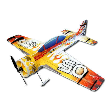
The Hawk model is designed as a simple multi-purpose, easy-build glider. It can be built in several
configurations including a free-flight chuck glider with a choice of two different wing styles or RC model
with micro servos (not included).
You can quickly and easily test the effect of adjusting ailerons, flaps, rudder and elevator on the flight
characteristics of the model. This is facilitated using flexible wire hinges on each of the control surfaces.
To start construction, you will need a straight, flat worktop, modelling pins, sandpaper, glue (we
recommend using thin Cyanoacrylate (CA) glue or Super ‘Phatic adhesive, available from Deluxe
Materials in the UK at www.deluxematerials.co.uk). Your choice of paint can also be applied to
customise the model but use sparingly as this will add weight to your model.
In these instructions we describe the basic building steps required to complete the model. If necessary,
please consult the help and advice of someone who has the acquired skills required to complete the
model.
The nose section of the fuselage, comprising parts 5,6,7 & 8, has been taped together in the correct
sequence of assembly. Carefully remove the tape keeping the parts in the same sequence for gluing
together.
Next, cut two 12mm lengths of dowel and chamfer the ends. These dowels (part 4) are inserted into the
predrilled holes in the nose sections, parts 5,6 & 7 to align the parts whilst gluing together.
Note: Due to possible variations in the diameter of the dowel material, it may be necessary to lightly
sand the outside diameter to reduce their size to accurately fit the holes.
Do NOT stick the 14mm dowels in place.
Once assembled and glued, allow the nose section to fully set on a flat surface. Secure with pins if
necessary.

Before gluing the veneer sidewalls (part 8) in place, sand the nose according to the plan (top view).
Ensure that the rear of the front section tapers down to the fuselage carbon tube as shown in the plan.
Now glue the outer veneer parts 8 onto each side of the nose assembly ensuring that they are centered.
If desired, apply several light coats of varnish or paint to the completed nose section and sand between
coats.
Chamfer the ends of the carbon fuselage rod and insert into the rear of the nose section. When happy
with the fit, glue into place.
Carefully sand the slots in the vertical fin and the horizontal stabilizer to precisely fit into each other.
Now glue these parts together and pay careful attention to the perpendicularity of the glued surfaces.
The aim is to achieve a perfect 90-degree angle between the two surfaces for stable flight. Ensure that
the parts remain perpendicular whilst drying.
Once the joint has dried fully, fit and glue the two stiffeners part no.12 in place.
Apply one coat of varnish (or similar) to the finished joint, if desired.
Now glue the parts 10 & 11 into place to create the seat for the rear of the fuselage carbon rod. (see the
plans for their correct position).
For the time being we will NOT attach the tailplane to the rear of the fuselage carbon rod.
Construction of the main wing assembly:
Prepare the wing sections and shape them in accordance with the plans. To achieve the correct shape,
start by gluing the upper veneer part no. 2 to the upper surface of the wing tip in the position shown on
the plans. Use modelling pins to hold in place whilst the glue dries.
Once the glue has dried, trim the excess wing trailing edge as per the plans and cut/sand the wingtips to
the shape of the veneer part no.2.
On the underside of the wing draw a pencil line 1mm inside the line of the veneer part no. 2.
Chamfer the area from this pencil line to the wingtip down to a thickness of approximately 1mm.
Now fit and glue the bottom veneer part no. 2 so that it is flush with the wingtip.
The reinforcing veneer strip part no. 3 is now fitted and glued to the underside of the wing root. Once
the glue has dried, bend it around the leading edge of the wing and over the top of the wing. Glue it in
place and allow to dry. The veneer strips can be held in place whilst the glue dries using modelling pins.
Sand away any excess veneer.
Use a pencil to mark the position of the wing flaps and ailerons (according to the plans) and carefully cut
them out. Sand the edges of the flaps and ailerons to the required profile.
Cut 16 lengths of wire, each approximately 8mm long, to act as adjustable hinges for the control
surfaces.
Use a modelling pin to create holes in the trailing edge of the wing and in the control surface leading
edges to accept these wire hinges. The position of each wire hinge is shown on the plans. Fit each
control surface with hinges and ensure full movement of the surface. When ready, apply a few drops of
glue to wick down the wire hinge into the hole. Again, ensure full movement of the control surface.
If desired, apply a thin coat of varnish to the entire surface of the wing assembly. Lightly sand when dry.
Chamfer the wing roots to the correct angle to achieve the required dihedral as shown on the plans.

Stick the two wing sections together and check for correct dihedral whilst the glue dries. Note: place a
block or book under one wing tip and adjust until the correct dihedral value is measured, as shown on
the plans.
Once the wings have fully dried, insert the rear end of the fuselage carbon rod into the front of the
tailplane assembly.
From the front, check the alignment of the wings and tailplane then glue together.
Make any necessary adjustments by rotating the rear section to ensure a perfect alignment with the
front section. This is critical to ensure a fully aligned, efficient airframe.
Allow to fully dry before further handling.
Adjusting the centre of gravity for stable flight:
Note: The centre of gravity is the balance point of the aircraft. For stable flight it is crucial to achieve the
correct centre of gravity in accordance with the position marked on the plans. This position is marked as
an area between two black and white segmented circles on the plans labelled GC. We recommend
marking this location on the actual model to facilitate checking prior to each flight.
Balance the model by inserting the required amount of supplied weights into the hole on the top of the
nose section (the centre of gravity position is marked on the plans). When finished, plug the hole.
For free flight use, the required flight characteristics can be achieved by setting the position of the
ailerons, flaps, rudder and elevator. The wire hinges allow free movement of these control surfaces and
hold them in the desired position during flight.
Always launch the model directly into a gentle breeze or still air.
With the correct center of gravity, if the model noses toward the ground, slightly bend the elevator up
until level flight is achieved.
If the model noses up, correct with a small amount of down elevator.
The model should glide smoothly with a reasonable and pleasing rate of descent.
A tow hook can be screwed into the nose of the model to facilitate launching.
The model can then be launched using about 15m of cord or elastic catapult.
(recommend 5m of quality rubber 3x3mm or 6x1mm and 10m strong cord/nylon).
To launch the model with a circular throw, start by throwing it gently and make any necessary
adjustments before using more throwing force. After adjusting the model, gradually increase the
throwing force to the required level for longer flight duration.
The HAWK model is not a toy. It is important to take great care in constructing the model and in its safe
operation.
Wishing you many successful and enjoyable flights with your new HAWK glider.
Watch out for new additions to our great range of model aircraft kits on our website:
www.craftyproducts.co.uk
Table of contents
Popular Toy manuals by other brands
Kids II
Kids II Bright Starts 8352WS manual

Canon
Canon CREATIVE PARK (Moving) Performing white... Assembly instructions

Eduard
Eduard 49 597 manual
Mountain Models
Mountain Models Tom-E-Boy Micro manual
Wild Planet
Wild Planet Disney Mickey's Mouse-ke-TAG Quick start quide
Lionel
Lionel Playtime Playground owner's manual
