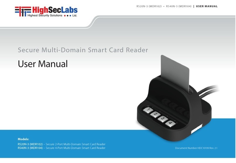
High Sec Labs RS20N-4 User manual

RS20N-4 • RS40N-4 | QUICK CONFIGURATION GUIDE
Secure Multi-Domain Smart Card
Reader
Models:
RS20N-4 Secure 2-Port Multi-Domain Smart Card Reader
RS40N-4 Secure 4-Port Multi-Domain Smart Card Reader
Intended Audience
This document is targeted at the following professionals:
•System Administrators.
•IT Managers with adequate knowledge of PKI
architecture.
Objectives
This document describes the fundamental configuration procedures
that are required to install the HSL Multi-Domain Smart Card
Reader.
Prerequisites
•Obtain and install the applications, drivers and files of the
cryptographic software (CSP) which corresponds to your selected
smart card vendor.
•Obtain a smartcard from your selected smart card vendor.
•Verify that your smart card setup works correctly on each PC
using a standard smart card reader prior to connecting the
MDR.
Hardware Terms
The following terms are used to describe
hardware elements in this document:
1. Numbered USB Cables: USB Cables with numbered connectors.
2. Card Reader Slot
3. PC Association Led
4. PC Number Button
5. PC Number Led
6. DIP Switch 1
2
3
4
5
6
Initial MDR Configuration Steps
Table 01 describes the initial MDR configuration steps
# Action Action Description Expected Behavior
1Install Smart Card
Applications
Verify that the applications, drivers and files of the cryptographic
software (CSP) that corresponds to your selected smart card vendor
are installed on all the computers that you plan to connect to the
MDR.
Note: Perform a computer restart in case needed to complete the
smart card application installation.
2 Turn PC ON Make sure that all the PCs are turned ON.
3Test Smart Card using a
Standard Reader
Verify that your smart card setup works correctly on each PC
using a standard smart card reader prior to connecting the
MDR.
4 Connect MDR to Power Connect the MDR to Power 1 second beep sound. All LED lights
blink once.
5Connect USB
Cables to PCs Connect the MDR USB cables to the computers. Cable
numbers correspond to the numbered MDR buttons. All PC Number LED lights blink constantly.
6Insert Smart Card
into the MDR Insert your smart card into the MDR reader socket.
Note: Make sure the smart card chip is facing towards you.
1 second beep sound. All lights are
OFF.
7Initial Association
with PC#1 Press PC Number Button#1 to initialize the MDR on
PC#1.
PC Number Button#1 light blinks for 5 seconds and when the
association is made, the light is ON constantly.
The MDR appears as a smart card reader under PC#1
device manager.
8Initial Association
with PC#2 Press PC Number Button#2 to initialize the MDR on
PC#2.
Notes: Repeat the process on the remaining PCs.
PC Number Button#1 light turns OFF. PC Number
Button#2 blinking 5 seconds and then light turns ON
constantly.
The MDR appears as a smart card reader under PC#2
device manager.
©2019 All rights reserved. HSL logo and product names are trademarks or service trademarks of HighSecLabs Ltd (HSL).
All other marks are the property of their respective owners. Images for demonstration purposes only. HDC19964 Rev 1.0

Table 02 Operational Modes:
# Mode Description DIP Switch
1Manually open all
channels one by one
The user has to manually activate assosiation with the PCs for the first time, by
pressing channel buttons on the MDR. Once it is connected, it remains active and the
user can keep working with all the PCs.
1
7 Single channel active The User will press the channel button each time for the MDR will associate itself with
the PC. Once the user presses another channel, the previous disconnects. 1 +7
8 Auto channel
association
The User will press channel 1 only once and the MDR will associate itself to all the
connected PCs one by one automatically. 1 +8
Working with the MDR
One completing the initial MDR configuration steps the MDR
is ready for use allowing simultaneous usage of a single
smartcard with multiple PCs.
Smartcard Removal Behavior
Removing the smartcard from the MDR immediately de-associates
the MDR from all coupled PCs. As a result, smartcard-aware
applications will notice the smartcard absence and respond
accordingly.
For example, a Windows PC that is configured to require
smartcards for user logon may be set to lock the user’s desktop
once the smartcard is removed.
Re-associating the MDR after Smartcard
Removal
In order to continue using the smartcard (after it’s been removed
from the MDR), the user has to insert the smartcard into the MDR
and complete steps 6-8 in order to re-associated the MDR with all
the corresponding PCs.
De-associating the MDR from a Specific PC
Long pressing a PC Number Button is the equivalent of removing
the smartcard only from the PC which corresponds to that button
without affecting other associated PCs. To re-associate that PC
with the MDR, press the PC Number Button to initialize the MDR
(as described in step 7).
The de-association option is useful in any case a user wants to de-
associate the MDR from a specific PC, without interfering with other
PCs which are associated with the MDR.
For example, when a user has to lock PC#1 by removing the
smartcard yet remain logged-on to PC#2, or when a certain PC is
not successfully associated with the MDR and the user wants to
re-associate it.
Reset
Hold one of the connected channel buttons for 7 seconds to reset
the device and its association with the PCs.
MDR Operational Modes
Operational Mode settings determines how Active/Passive PC Modes
are set. For example, when the MDR Operational Mode is set to
Manual, the user has to manually press the PC Number Button
corresponding to the PC that requires access to the smartcard.
When the MDR Operational Mode is set to dynamic, auto-
association methods are used to determine which PC will be set
as Active.
For example, when the MDR operational mode is set to Activity-
Detection Auto Association, the MDR will automatically actively
associate itself to the computer which requires smart card access
based on an activity detection algorithm.
To preset which MDR Operational Mode is in use (Manual / Auto...etc),
there is a hardware dual in-line package (DIP) switch situated in the
underside of the base. See the switch configuration settings in Table
02, column DIP Switch.
RS20N-4 • RS40N-4 | QUICK CONFIGURATION GUIDE
Power Requirements: External, wall-mounted power supply 12VDC, 5W maximum
©2019 All rights reserved. HSL logo and product names are trademarks or service trademarks of HighSecLabs Ltd (HSL).
All other marks are the property of their respective owners. Images for demonstration purposes only. HDC19964 Rev 2.0
DIP Switch Configuration
1. To change the DIP switch settings, hold
the MDR with the underside facing you. In
this position, the DIP switch should be at
the upper right corner.
2. Gently remove the DIP switch cover.
3. The switch includes 8 slides numbered from
1 to 8, ordered from left to right.
4. When pulled down, slide status is OFF. When pulled up, slide status
is ON.
5. To activate an operation mode, pull down its corresponding slide.
6. Multiple slides can be turned OFF (pulled
down) at the same time.
7. Refer to Table 02 to adjust DIP switch settings with your work
scenario.

Safety and Regulatory Statements
Safety Symbols
This one or more of the following symbols may be included in your
product documentation and/or on the product.
Instructions: This symbol is intended to alert the user to the
presence of important operating and maintenance
(servicing) instructions in the product user manual.
Dangerous Voltage: This symbol is intended to alert the user
to the presence of uninsulated dangerous voltage within the
product’s enclosure that may be of sufficient magnitude to
constitute a risk of electric shock to persons.
Power On: This symbol indicates the principal on/off switch
is in the ON position.
Power Off: This symbol indicates the principal on/off switch
is in the OFF position.
Protective Grounding Terminal: This symbol indicates a
terminal which must be connected to earth ground prior to
making any other connections to the equipment.
Safety Precautions
WARNING: To avoid a potentially fatal shock hazard and possible damage to
equipment, please observe the following precautions.
•Instructions: Do not disable the power grounding plug. The
grounding plug is an important safety feature.
•Plug the power cord into a grounded (earthed) outlet that is
easily accessible at all times.
•Disconnect the power from the product by unplugging the
power cord from either the electrical outlet or the product. The
AC inlet is the main disconnect for removing power to this
product. For products that have more than one AC inlet, to
remove power completely, all AC line cords must be
disconnected.
•This product has no serviceable parts inside the product
enclosure. Do not open or remove product cover.
CAUTION: Some HSL products contain a lithium battery. This battery is not a
field replaceable item, and replacement should not be attempted by a user.
If errors occur when using the product and the battery is suspected, contact
HSL Technical Support.
WARNING: For Service Personnel Only - There is a risk of explosion if the
battery is replaced with an incorrect type. Dispose of used batteries
according to the manufacturer’s instructions.
This product is for use with other products that are Listed or
Certified by a Nationally Recognized Testing Laboratory (NRTL).
NIAP Protection Profile
This product is certified to the NIAP Protection Profile PSD version
4.0 certification for peripheral sharing switch devices.
Installation Precautions
Do not connect this product to computing devices that:
•are TEMPEST computers
•include telecommunication equipment
•include frame grabber video cards
•include special audio processing cards.
WARNING: Peripherals' Warning - For security reasons, this product does
not support wireless keyboards. It is recommended not to connect a
microphone or headset to the audio output port.
Security Vulnerability
If you are aware of a potential security vulnerability while installing
this product, contact Technical Support immediately by:
•Web form: www.highseclabs.com/support/case/
•Email: security@highseclabs.com
•Tel: +972-4-9591191/2
WARNING: Unit Enclosure Warning - If the unit’s enclosure appears
disrupted or if all LEDs flash continuously, remove the product from service
immediately and contact Technical Support.
Change Management
For change management tracking, perform a quarterly log check to
verify that the RFD was not improperly used to override the current
device policy by an unauthorized person.
This manual suits for next models
1
Other High Sec Labs Card Reader manuals
Popular Card Reader manuals by other brands
Rocket Fish
Rocket Fish RF-CRDRD Guía De Instalación Rápida
Bio-Tek
Bio-Tek FL600 Hardware guide
HIK VISION
HIK VISION DS-K1108AM user manual
Blackbe;rry
Blackbe;rry Smart Card Reader Safety and product information
IDTECH
IDTECH ViVOpay VP3300 Series user manual
HIK VISION
HIK VISION DS-K1T500 quick start guide
