FAAC ParkLite TR User manual

TR ParkLite rev. A
INSTALLATION MANUAL
Ticket Reader
ParkLite
Ticket Reader
ParkLite

2
ENGLISH ENGLISH
CE DECLARATION OF CONFORMITY
Manufacturer: FAAC S.p.A.
Address: Via Benini, 1
40069 - Zola Predosa
BOLOGNA - ITALY
Declares that: the ParkLite Ticket Reader
•conforms to the essential safety requirements of the following EEC
directives:
73/23/EEC and subsequent amendment 93/68/EEC.
89/336/EEC and subsequent amendment 92/31/EEC and 93/68/EEC
•and also conforms to the following standards:
EN 50081 -1 EN 60555 - 2 IEC 801 - 2
EN 50082 -1 EN 60555 - 3 IEC 801 - 3
EN 60335 -1 EN 55022 IEC 801 - 4
EN 60204 -1 EN 55014
Additional notes:
This product underwent a test in a typical, uniform configuration (all
products of FAAC S.p.A.).
Bologna, 01 January 2006
The Managing Director
A. Bassi

3
ENGLISH ENGLISH
GENERAL SAFETY OBLIGATIONS
1) IMPORTANT! To ensure the safety of people, it is important that all the instructions be carefully read.
Incorrect installation or incorrect use of the product could cause serious harm to people.
2) Carefully read the instructions before beginning to install the product.
3) Packing materials (plastic, polystyrene, etc.) must not be left within the reach of children, because these materials are
potential danger sources.
4) Keep the instructions for future reference.
5) This product was designed and built exclusively for the use indicated in this documentation. Any other use not expressly
indicated could compromise the condition of the product and/or be a source of danger.
6) FAAC declines any responsibility due to improper use or use other than the use for which the product is intended.
7) Donotinstalltheequipmentinanexplosiveatmosphere.thepresenceofgasorinammablefumesisaseriousdangerto
safety.
8) FAAC is not responsible for failure to use Good Workmanship in installing the product.
9) The installation must be carried out by observing standards EN12453 and EN12445.
10) Before attempting any action on the system, cut out the electrical power supply.
11) Install an omnipolar switch upstream of the power supply line for the ParkLite Ticket Reader with contact opening
distance of 3 mm. or more. We advise you to use a 6A thermal breaker with omnipolar switching.
12) Make sure that a differential switch with a threshold of 0.03A is installed upstream of the system.
13) Make sure that the earthing system is expertly made and connect to it the Yellow/Green earth terminal of the Ticket
Reader.
14) FAACdeclinesallresponsibilityforthesafetyandefcientoperationoftheTicketReader,ifsystemcomponentsnot
produced by FAAC are used.
15) For maintenance, strictly use original FAAC parts.
16) Do not in any way modify the components of the ParkLite Ticket Reader.
17) The installer must supply all information on the operation of the system and hand over to the user, the “User’s Guide”
which accompanies the product.
18) Theusermustnotinanywayattempttorepairortotakedirectactionandmustcontactqualiedpersonnelonly.
19) Anythingnotexpresslyspeciedintheseinstructionsisnotpermitted.
WARNINGS FOR THE INSTALLER

4
ENGLISH ENGLISH
5
5
6
7
7
7
8
8
8
8
8
8
9
9
10
11
11
11
12
13
13
14
15
15
15
16
16
16
16
16
17
1. DESCRIPTION AND TECHNICAL SPECIFICATIONS...............................................................
1.1 DESCRIPTION....................................................................................................................................
1.2 TECHNICAL SPECIFICATIONS.......................................................................................................
2. INSTALLATION OF COMPONENTS.............................................................................................
2.1 LANE CHARACTERISTICS.............................................................................................................
2.2 ESSENTIAL REQUIREMENTS........................................................................................................
2.3 CONSTRUCTION OF LOOPS..........................................................................................................
2.3.1 INSTALLATION.............................................................................................................................
2.3.2 CONSTRUCTION...........................................................................................................................
2.3.3 NUMBER OF WINDINGS.............................................................................................................
2.4 MASONRY PREPARATIONS...........................................................................................................
2.4.1 LAYING THE FOUNDATION PLATES........................................................................................
2.4.2 FASTENING...................................................................................................................................
2.5 COMPONENT DIMENSIONS..........................................................................................................
2.6 PREPARATION OF CHANNELS.....................................................................................................
2.7 POSITION OF EQUIPMENT............................................................................................................
3. ELECTRICAL PREPARATIONS....................................................................................................
3.1 SAFETY INSTRUCTIONS...............................................................................................................
3.2 TYPES OF CABLES..........................................................................................................................
4. ELECTRICAL CONNECTIONS.....................................................................................................
4.1 CONNECTIONS ON INTERFACE BOARD...................................................................................
4.2 DATA TRANSMISSION LINES.......................................................................................................
4.3 INTERCOM CONNECTION............................................................................................................
5. SETTING OF COMPONENTS........................................................................................................
5.1 DETECTOR CONFIGURATION......................................................................................................
5.2 THERMOSTAT ADJUSTMENTS.....................................................................................................
6. MANAGEMENT UNIT.....................................................................................................................
6.1 P.LITE COBRA BOARD...................................................................................................................
6.2 JUMPER FUNCTION.......................................................................................................................
6.3 RS485 LINE TERMINATION...........................................................................................................
6.4 ELECTRICAL CONTROL WIRING................................................................................................
Contents

5
ENGLISH ENGLISH
The ParkLite Ticket Dispenser was designed to manage the exit
lane of a parking area. This function can be carried out by the
equipment only subordinately with respect to the “ParkLite”
management software.
The unit which controls exit from the gate must be connected to
the data Controller PC, and to the relevant application program.
This type of connection makes it possible to exploit all the ser-
vices offered by the system, thanks to the support of the parking
area management program.
The ParkLite Ticket Reader is available in three versions:
• ParkLite TR
• ParkLite TR-TAG
• ParkLite TR-MAG
All models are provided with the ticket reading module, for
managing single-stay users.
Thermostat
Plastic box with control
board Cobra 5000 P.Lite
Metal protection for
Power Feeder and wire
terminal-boards.
Heater
The equipment was designed to read tickets with a 22-character
interleaved 2/5 barcode, issued by the ParkLite Ticket Dispensers
installed on the area entry lanes, or by the ParkLite Decentralised
Cash Desks, as substitute tickets.
The ParkLite Ticket Reader reads the ticket by means of a one-
way 16-line laser scanner, at a scanning speed of 1200 times a
second.
“ParkLite TR-TAG” has a reader of passive proximity cards,
which detects memory-stored codes at a frequency of 125 Khz.
“ParkLite TR-MAG” has a magnetic card reader, which reads
magnetic bands coded on a Standard 2 ISO track.
The equipment is operational only when it is on-line with the
management software.
TheTicketReadercanbeconnectedtoaspecicintercom
control unit (optional), which enables the operator to remotely
communicate with the user situated on the exit lane.
Connection with two magnetic loops, able to detect the pre-
sence and transit direction of the vehicle, is obligatory for all
models.
The engagement and disengagement of these sensors, allows
the Ticket Reader to enable the ticket/card reading modules,
control the car’s travelling direction, supply the closing com-
mand to the beam and do the counting.
The location of the loops, in common with the equipment for
controlling access in the exit lane, must observe to the letter
the instructions in the following chapters.
The Ticket Reader directly opens/closes the beam with an
impulsive logic, providing the open/closed command.
For this reason, when creating exit gates for vehicles, solely
beams which manage the car park logic must be used.
The vehicles-only lanes must be provided with appropriate
horizontal and vertical signs indicating “transit by pedestrians
forbidden”. Likewise, if there are any pedestrian crossings
on the lanes, all the beams must be made safe and suitable
warning signs must be installed. See the current legal regula-
tions on the matter (in particular standards: EN12453 and EN
12455).
To avoid damage to transiting vehicles, the barriers must be
equipped with a safety option, which makes it possible to
connect the “vehicle present” signal, received from the transit
loop, to avoid accidental closure. This characteristic must be
enabled also when photocells installed under the beam are
used.
Card reader
Intercom
1.1 DESCRIPTION
1. DESCRIPTION AND TECHNICAL SPECIFICATIONS
g.1ParkLiteTicketReader
Ticket reading
location
Laser scanner

6
ENGLISH ENGLISH
DIMENSIONS 350x1050x170 (Width x Height x Depth in mm)
WEIGHT 30 Kg
CABINET PROTECTIVE TREATMENT Cataphoresis
CABINET PAINT Opaque grey and blue micalised polyester
POWER SUPPLY 230 Vac (+6% - 10%) 50 Hz
OPERATING AMBIENT TEMPERATURE -20°C / +50°C
ABSORBED POWER WITH HEATER 100 Watt
ABSORBED POWER WITHOUT HEATER 45 Watt
INPUT/OUTPUT CONNECTIONS Through pull out terminal-boards, on control board
METAL DETECTOR FOR LOOP CONNECTION Integrated,with two channels and doubled outputs
POWER SUPPLY Switching on 2 channels; 115Vac - 230Vac
HEATER Yes
TEMPERATURE MAINTENANCE THERMOSTAT Yes (value range from 0° to 30° Celsius)
DATA TRANSMISSION LINE RS485
CONTROL UNIT
COBRA 5000 P.Lite board
RAM CONTROL UNIT 512 KByte
USER CAPACITY 5000
EVENT CAPACITY 15000
BARCODE READER One-way laser scanner
SCANNING RESOLUTION 16 lines
SCANNING SPEED 1200 per second
READ TICKET DETECTION Barcode with 22 characters 2/5 interleaved
Tab. 1 Characteristics present on all ParkLite Ticket Reader models
Tab.2 Characteristics present only on ParkLite TR TAG
Tab. 3 Characteristics present only on ParkLite TR MAG
TYPE OF CARD READER Contact Less reader of Passive Transponders
CARD DETECTION FREQUENCY 125 KHz
TYPE OF READ CARDS CODING UNIQUE
CARD DETECTION DISTANCE Max. 10cm.
CARD FORMAT ISO (86x54x0,78mm)
TYPE OF CARD READER Magnetic card swipe reader (100% of track)
TYPE OF READ CARDS CODING Standard 2 ISO track (from 1 to 37 characters)
CODING CODE High coercitivity 4000 Oe
CARD FORMAT ISO (86x54x0,78mm)
1.2 TECHNICAL SPECIFICATIONS

7
ENGLISH ENGLISH
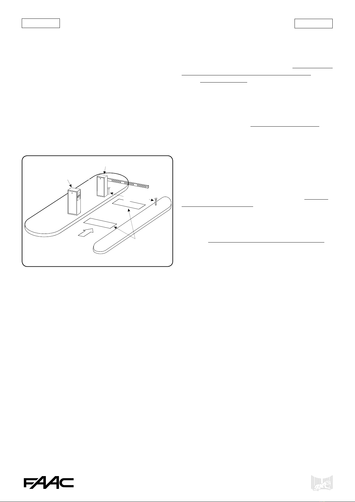
All the components of an exit lane of a ParkLite automated
parking system, are directly managed by the Ticket Dispenser.
The exit lane of a parking area consists of:
• Nr. 01 ParkLite Ticket Reader.
•Nr. 01 620 rapid barrier RH.
•Nr. 02 Magnetic loops.
•Nr. 01 Pair of photocells.*
•The exit lane from a parking area managed by the Ticket
Reader must be constructed so that the vehicles coming from
different directions can easily get close to the column, to
enable the user to read the ticket or a valid card without any
difculty.
• The equipment must be installed on an island 15 cm. above
road level. If this is not possible, protective structures must be
installed around the base of the two columns (TR and barrier
620) and the Ticket Reader must be raised 15 cm. above the
lane paving, so that the devices for reading and treating the
tickets for exit from the parking area are located at the right
height.
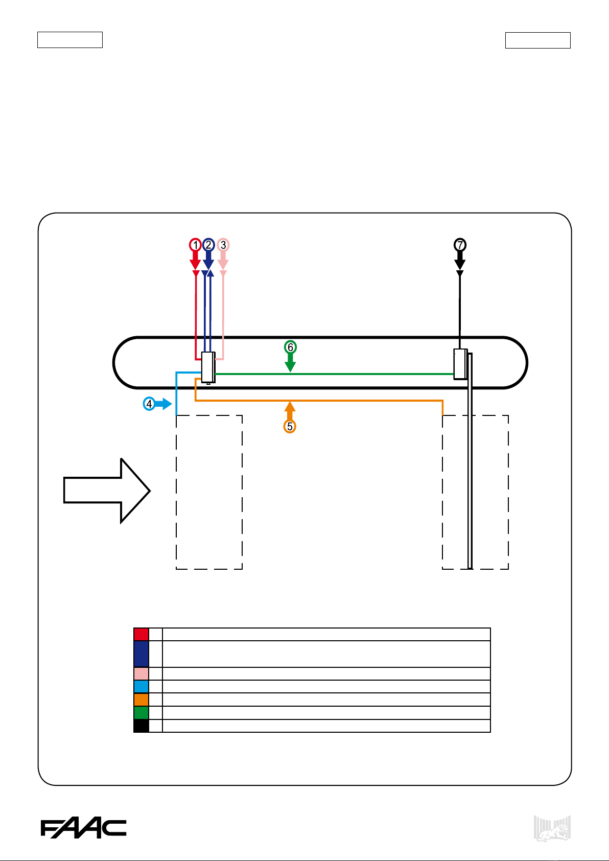
• The Ticket Reader operates only if the magnetic loops have
been correctly connected to it. In fact, the column was desi-
gned to manage all the user exit from lane stages, exploiting
thesetwoelements,whicharegenerallydenedas:presence
loop and transit loop.
g.2Exitlane
The construction and deployment of the loops is fundamentally
important to ensure that the system functions correctly. For this
reason, observe to the letter all the instructions described in the
following paragraphs:
2.3 Making the Magnetic Loops
2.7 Positioning the equipment.
• The power cables and the cables for connecting the equi-
pment in the parking system must have the characteristics
indicated in paragraph:
3.2 Type of cables.
Furthermore, all the instructions in paragraph “General safety
rules” on page 3 must be respected, and, with reference to the
specicelectricalpreparations,asdescribedinparagraph:
3.1 Safety rules.
• The Ticket Reader was designed to manage automatically
the exit of vehicles from a parking area. Therefore, transit by
pedestrians must be forbidden in the area reserved for transit
of vehicles. Moreover, appropriate signs prohibiting transit by
pedestrians must be installed. Where it is not possible to have
an entrance/exit gate reserved exclusively for pedestrians, the
current legal regulations on the subject must be absolutely
observed; (in particular standards: EN 12453 and EN 12445)
• The lane must not allow the exit by two or more vehicles
side by side. For this reason, the width of the lane must be
appropriately sized, according to the type of vehicle generally
used.
• Sufcientspacemustbeprovidedforeveryequipmentof
the parking system, so that all the necessary installation and
maintenance operations can be smoothly carried out.
• Position the Ticket Reader so that it (laser scanner) is not
directly exposed to luminous radiation, which could be source
of disturbance during reading.
• Appropriate signs (not supplied by FAAC), indicating the
tariffs and the car park rules must be visibly shown on the
entrance lane to the car park.
* optional
NB.: All the equipment which can be used in the ParkLite
parking system, were designed and tested by FAAC, in
observance of the points mentioned above. In order to avoid
any kind of unforeseen behaviour, all the rules shown in this
manual must be observed.
2.2 ESSENTIAL REQUIREMENTS
620 rapid barrier RH
Photocells
Magnetic
Loops
Ticket Reader
2. INSTALLATION OF COMPONENTS
2.1 LANE CHARACTERISTICS

8
ENGLISH ENGLISH
The following instructions must be respected:
•Laytheloopsatleast15cm.fromxedmetalobjects.
•Laytheloopsatleast15cm.fromxedmetalgrilles.
•Lay the loops at least 50 cm. from moving metal objects.
•The loops must be laid at a depth of 30mm. to 50mm. from
the road surface.
•The loop must be made with a single cable, without making
any joints or shunts inside the pits.
•The two ends of the cable issuing from the loop perimeter
must be twisted or intertwined with each other at least 20 times
per meter, up to the connection inside the Ticket Reader.
•The twisted cable of the loop must be laid in pipes or cable
ducts separated from those used for other purposes (power
etc.).
2.3.2 CONSTRUCTION
The shape of the loops must be ‘rectangular’. The corners
must be cut at 45° to prevent the cable breaking, due to the
vibrations of transiting vehicles or possible settling of the road
paving.
There are two methods for making them:
• Lay a single single-pole cable with a cross section of
1.5 mm2, with double insulation, directly in a chase made in
the existing road paving.
• First construct a cable duct in PVC of the necessary shape,
insert a single-pole single-insulation cable with a cross-section
of 1.5 mm2inside it, and then lay the loop thus constructed
inside the chase.
NB.:inbothcases,respecttherequirementsspeciedinpoint
2.3.1.
described up to here, around the perimeter in which it must be
constructed.
Procedure for the above operation: insert the cable end from
the sharp edge providing access into the chosen seat, next run
it inside for a set of full ‘circuits’, to make a coil, and then
make the same cable come out from the point where it had
been inserted.
Fig. 3
The windings which must be made in order to construct the
loop correctly, depend on the dimension of the perimeter.
The dimensions of the loops to be laid on the lane managed by
the Ticket Reader, shown in the following chapters, call strictly
for the construction of 4 windings.
In fact, the system detects all the transit stages of the vehicles
on the entrance lane, making use of these devices. As a result,
fewerthanspeciedwindingswillnotmaketheequipment,
assigned to control the lane, operate correctly.
NB.: if there are metal nets under the paving (see the distance
of the metal grilles previously referred to), we advise you to
add 2 windings to the 4 obligatory windings.
Fig. 4
Loop consisting
of 4 windings
2.3 CONSTRUCTION OF LOOPS
2.3.1 INSTALLATION
2.3.3 NUMBER OF WINDINGS
The loop must consist of a precise set of windings of the cable

9
ENGLISH ENGLISH
2.4.2 FASTENING
Ticket Reader and/or 620 Barrier
• Using a level, check if the foundation plate is perfectly hori-
zontal before installing.
• Secure the upright to the plate with suitable nuts and
washers.
• Position the Ticket Reader so that it (laser scanner) is not
directly exposed to luminous radiation, which could be source
of disturbance during reading.
2.5 COMPONENT DIMENSIONS
The following pictures show the dimensions in millimetres of
the main lane equipment.
2.4 MASONRY PREPARATIONS
The foundation plate for securing the Ticket Reader is identical
to the one used for installing the 620 barrier. The drawing be-
low shows the dimensions and methods for laying them both.
2.4.1 LAYING THE FOUNDATION PLATES
Ticket Reader Dimensions
Fig. 6
Dimensions of 620 Barrier
Fig. 7
Dimensions in mm.
Fig. 5
The dimensions of the barrier rod obviously depend on many
different factors: lane width, gate height (in case of on-site
installations with cover), etc.
We advise you to determine the size of this element, so that it
can move freely.

10
ENGLISH ENGLISH
Before carrying out the masonry works required to make the
lane, prepare all the channels/ducts/raceways essential for
cable routing, for electrical connection of the system’s equip-
ment.
Lay the cable ducts, scrupulously observing the indications
shown in the lay-out below.
Separate ducts must be provided between: high voltage (230
Vac power cables) and low voltage (cables for: commands,
safety, intercom, serial data line, etc.).
Furthermore, appropriately size the diameter of the cable ducts
to be laid, in relation to the cross-section and number of cables
to be inserted. To this end please refer to section 3. Electrical
preparations of this manual.
Channel lay-out for Exit lane
Driving direction
1 Input of Ticket Reader power cables
2 Input and output of cables for data transmission line on RS 485
protocol
3 Input for intercom line cables
4 Vehicle Presence loop
5 Vehicle Transit loop
6
Open/Closed barrier commands + transit loop safety contact
7 Input of barrier power cables
2.6 PREPARATION OF CHANNELS
Fig. 8

11
ENGLISH ENGLISH
Equipment lay-out for managing vehicles on exit lane
3.1 SAFETY INSTRUCTIONS
•Before attempting any action on the system, cut out the
electrical power supply.
•Install an omnipolar switch upstream of the power supply
line for the device, with contact opening distance of 3 mm. or
more. We advise you to use a 6A thermal breaker with omnipo-
lar switching.
3. ELECTRICAL PREPARATIONS
•Make sure that a differential switch with a threshold of 0.03A
is installed upstream of the system.
•Make sure that the earthing system is expertly made and
connect to it the metal parts of the closing element.
•Apply all the instructions described in the preceding points to
all the lane devices, in addition to the Ticket Reader.
Fig. 12
Foundation plate
for ParkLite column
Foundation plate for
620 rapid barrier (RH version)
Driving direction
Presence loop
Transit loop
2.7 POSITION OF EQUIPMENT
To ensure the parking system operates correctly, all the equip-
ment of the exit lane must be positioned, strictly observing the
dimensions shown in the lay-out below:

12
ENGLISH ENGLISH
The characteristics of the cables, to be used for connecting the
Ticket Reader, are determined to ensure that the equipment and
all the devices connected to it operate well.
Electrical preparations for the ParkLite Ticket Reader lane
1 Flame-retardant cable 2 x 1,5 mm² + earth (power supply)
2 Single-pole cable 1,5 mm² with single or double insulation of the presence loop
3 Single-pole cable 1,5 mm² with single or double insulation of the transit loop
4Cable Belden 9841 or CEAM Y09842 with twisted pairs and screened for transmission on
data network with RS 485 protocol. All devices must be multidrop-connected as shown in
lay-out “Data Line Connections”
5 Shielded cable for intercom 2 x 1,5 mm² (if Legacy model).
Telephone pair 0,4 mm² - 275 Ohm/Km Line (Double wire), or telephone pair 0,6 mm² 122
- Ohm/Km Line (Double wire) (if Deluxe model)
6 Flame-retardant cable 2 x 0,5 mm² (input for barrier closure safety)
7 Flame-retardant cable 3 x 0,5 mm² (open/closed barrier commands)
Power supply
Presence
Loop
Presence loop
Transit
Loop
Transit loop
Converter
Controller PL
Personal Computer TD Slave TR Slave
RS 485 Data Line Intercom control unit Safety contact
Safety contact
Open/Closed commands
Power supply
Ticket Reader
230Vac VAC - 50 Hz
For this reason, you must use only the conductors with the
characteristics described in the table below:
3.2 TYPE OF CABLES
Fig. 10

13
ENGLISH ENGLISH
Most of the devices managed by the Ticket Reader are con-
nected via the Interface board. The lay-out below shows all
Equipment connection lay-out for ParkLite Ticket Reader
the connections that can be made, for all the types of uses for
which the equipment was designed.
4.
ELECTRICAL CONNECTIONS
4.1 CONNECTIONS ON INTERFACE BOARD
Fig. 11
NC Transit loop output
NA Transit loop output
C Transit loop output
NC Presence loop output
NA Presence loop output
C Presence loop output
Input 6 additional
Common input
Comune Open/Closed Barriera
Closed Barrier
Open Barrier
Input 2
Input 6
Additional inputs
Vehicle detection loops
on exit lane
620/640 barrier congured in P logic
Barrier photocell
620/640 barrier congured in P logic
Sch. RS 485 Polling Out
- RS 485 Polling Out
+ RS 485 Polling Out
Sch. RS 485 Polling In
- RS 485 Polling In
+ RS 485 Polling In
Power supply
Ticket Reader
230 Vac/50-60 Hz
Board 624 BLD
Board 624 BLD
Transit loop
Presence loop
Input 2 additional

14
ENGLISH ENGLISH
The Ticket Reader must be connected to a data transmission
line, so that all the necessary information can be transmitted/
received,inaspecicmanagementunit,towhichtheequip-
ment will be slaved. In the higher performance systems, all the
devices which control entrance/exit to/from the parking area,
are controlled by a Personal Computer (data controller) by
means of the ParkLite software. The lay-out in the following
gureshowstheconnectionofthevarioustypesofequipment
which can be connected to the data transmission line. In addi-
tion to this, a table summarises the characteristics required for
operation of the data communication networks.
Connection of data lines in a system operating on-line with controller PC and ParkLite management software
4.2
DATA TRANSMISSION LINES
Fig. 12
Network connection between Concentrator PC and NET PC
• The concentrator PC must share the program’s (ParkLite) work directory with all the NET
computers for access, reading and writing.
• If the system uses NET stations, both the concentrator PC and the NET PC must have a
static address assigned to them..
• The fundamental parameters for network connection between PCs. such as: IP address,
Netmask, Gateway, etc, must be supplied by the customer’s network administrator.
RS 485 Data transmission line
• Use a paired, twisted and screened cable for transmission on data network with RS 485
protocol, type Belden 9841 or CEAM Y09842 or with identical characteristics.
• All devices must be multidrop-connected as shown in lay-out. .
• A maximum of 31 devices can be connected for every line output from the converter.
• The total maximum distance of the network must not exceed 1200 mt..
• Insert a 120 Ohm termination resistor (insert by shifting a jumper on the Cobra control
unit or on the converter) at the end of the line..
• Star-type connections are not permitted.
• Do not make any joints on the data transmission cable.
TCP/IP Ethernet
LAN
Network
10/100 MBit
Concentrator NET
Personal ComputerPersonal Computer
Converter Controller PL Controller PL
TD Slave TR Slave
Controller PL
Wired network
socket (RJ45)
Wired network
socket (RJ45)
Patch cord for connec-
tion to LAN network
Connect to the Com serial port of PC
(connector DB9 male)

15
ENGLISH ENGLISH
The intercom is an optional item and can be supplied in two
different models, named:
• LEGACY
• DELUXE
The connection of the intercom line for both models must be
made via a terminal-board installed on a DIN guide, which is
located under the interface board. To connect the conductors,
refertothelay-outshowninthefollowinggure:
Intercom connection
Fig. 13
NB.: connection to the intercom control unit depends on the
model used. To this end, consult the manual of the intercom
that was bought.
5. SETTING OF COMPONENTS
5.1
DETECTOR CONFIGURATION
The ParkLite Ticket Reader is supplied with the built-in DP2
two-channeldetector.Thisdeviceisttedintheinterface
board and detects vehicles transiting on the entrance lane. The
following image shows the board’s essential components:
Detector DP2
The detector can be set by using the 8 dip-switches located at
the side of the control board. Varying the position of each dip-
switch enables you to change the operational characteristics
of this component. The following steps show all the
congurationsthatcanbeperformed.Inadditiontothis,the
tables show the recommended value in blue.
Sensitivity
For each channel, you can change the inductivity sensitiveness
which a vehicle must vary to activate the relevant output of
the detector. This parameter is adjusted separately for each
channel, with the aid of two dip-switches
Frequency
Theoperatingfrequencyofthedetectorcanbecongured
on two levels, by dip-switches 4 and 8, separately for each
channel. It is essential to differentiate the frequency among the
channels of the detectors which command two adjacent loops,
in order to avoid any kind of noise.
Presence time and reset
Dip-switches 3 and 7 enable you to set a continuous detection
time of 5 minutes, after which a reset and a consequent self-set
are performed automatically. This type of setting is normally
not recommended for parking systems, because the cars may
stay on the loops for some time, e.g. waiting for a vehicle to
come out when the area is full.
Signalling LEDs
The green LED signals that the detector channel is operating,
whereas the red LED supplies information on the status of the
relay according to loop condition. Signals are shown separately
for each of the 2 channels.
The following table summarises the detected conditions.
4.3
INTERCOM CONNECTION
Fig. 14
NB: for further information about the DP2 detector, please
consult the manual of this device
Common contact
Line
Service
Green Led
Red Led
Channel 2
Green Led
Red Led
Channel 1
8 Frequency
7 Hold time
6 Sensitivity B
5 Sensitivity A
4 Frequency
3 Hold Time
Sensitivity B
Sensitivity A
Channel 1
Channel 2
Sensitivity Channel 1 Channel 2
Low DIP 01 = OFF
DIP 02 = OFF
DIP 05 = OFF
DIP 06 = OFF
Medium-Low DIP 01 = ON
DIP 02 = OFF
DIP 05 = ON
DIP 06 = OFF
Medium-high DIP 01 = OFF
DIP 02 = ON
DIP 05 = OFF
DIP 06 = ON
High DIP 01 = ON
DIP 02 = ON
DIP 05 = ON
DIP 06 = ON
Frequency Channel 1 Channel 2
Low DIP 04 = OFF DIP 08 = OFF
High DIP 04 = ON DIP 08 = ON
Presence time Channel 1 Channel 2
5 minutes DIP 03 = OFF DIP 07 = OFF
Innity DIP 04 = ON DIP 07 = ON
Detector Status Green Led Red Led
Not powered OFF OFF
Self-setting Flashing light OFF
Loop free ON OFF
Loop engaged ON ON
Faulty loop OFF ON

16
ENGLISH ENGLISH
To ensure that the various modules used by the Ticket Reader
operate in optimum conditions, a temperature of 22° Celsius must
be maintained inside the column. This characteristic will ensure
that the laser scanner operates at its best, when the ticket is read.
This is in addition to eliminating any condensation accumulated
inside, due to possible temperature ranges between day and night.
We therefore advise you to always power the Ticket Dispenser
and adjust the thermostat knob to 22°C.
6. CONTROL UNIT
6.1 P.LITE COBRA BOARD
TheTicketReaderelectroniccontrolunitisdenedas:Cobra
P.Lite.Ithasspecicallycreatedrmwareforcommandingall
devices which need to be controlled on the exit lane from the
parking area.
The board manages some processes in a fully independent way,
whereas others can be subordinated through the board to the
ParkLite management software.
We must underscore the fact that every equipment for treating
tickets and cards in the ParkLite system uses this type of unit.
The various devices of the system (Ticket Dispenser, Ticket
Reader, Cash Desk, etc) make use of this control board with
thesamermware.Thefunctiontowhichtheequipmentis
addressed, is acquired by inserting a jumper, located on the
board’s CN1 connector.
Whenever the Ticket Reader is powered up, the Cobra P.Lite
control unit controls the function to which it is delegated,
throughthejumperttedontheCN1connector,anditsets
itselftomanageallthespecieddevicesforthatuse.
Thereforethisjumpermustbecorrectlytted.
Obviously, the Ticket Reader is supplied with the jumper
already set in the right position. Fig.15 shows all the settings
whichcanbecarriedoutonthemanagementunit.Thisgure
is included in order to be used, if this board has to be replaced
on the equipment.
6.3 RS485 LINE TERMINATION
On the Cobra P.Lite board, there is a connector which makes
itpossibletota120OhmterminationresistorontheRS485
data transmission line.
Weshouldstressthatthisresistormustbettedonly if the
equipment is located on one of the ends of the line section.
UsetheCN8connectortotthisresistor.
Figure 15 shows the insertion of this characteristic.
Set-up of function jumper and insertion of termination resistor
5.2
THERMOSTAT ADJUSTMENTS
6.2 JUMPER FUNCTION
Fig. 15
Set-up of function Jumper
NB: make sure that the jumper is positioned between E and F of CN1.
Termination resistor on RS485 network
Position of Jumper in CN1
Description of function
A TICKET DISPENSER
B
CASH-DESK (ON LANE OR DECENTRALISED)
C SUBSCRIPTION (VEHICULAR)
D SUBSCRIPTION (PEDESTRIAN)
E TICKET READER
Position of Jumper in
CN8 Description of function
DOWN (Toward ALI board) 120 OHM RESISTOR NOT INSERTED
R (UP) 120 OHM RESISTOR INSERTED
Cobra P.Lite board

17
ENGLISH ENGLISH
Wiring on the electronic control board
Fig. 16
Wiring on Cobra P.Lite board
Wiring on Pratic 503 board
Cobra P.Lite
Destination Function
M1
MAG 100 reader
CM1 (Pratic 503)
Connection of MAG100 reader (ParkLite TR-MAG)
Connection of Pratic 503 board for managing reader (ParkLite TR-TAG)
M11 CN3 on Interface board Input for data transmission network in RS485 for polling
M12 CN3 on Interface board Output for data transmission network in RS485 for polling
M10 CN5 on Interface board DirectPCconnectionforconguration(CN7connector,Interfaceboard)
M14 Not used None
M15 Not used None
M16 Power feeder +24Vdc power supply to board
M8 CN1 on Interface board Open Barrier Command (Output 1)
M7 CN1 on Interface board Closed Barrier Command(Output 2)
M6 Not connected Output 3
M5 Not connected Output 4
M4 CN2 on Interface board Inputs: loops engage/disengage (in5 and in1), area down-count or reserve (remaining)
M13
Ticket Reader Scanner
Receive the data of the ticket read by the laser scanner
Pratic 503 Destination Function
CM1 M1 on Cobra P.Lite board Connection of reader input to control unit
CPROX Transponder reader Connection of passive transponders reader 125 Khz
CLED Front Led Connection of front LED signalling outcome of ticket reading
Cobra P.Lite board
PRATIC 503 board
6.4 CONTROL UNIT WIRING
Thetableinthefollowinggureshowsthevariousinternal
connections with the electronic control unit housed in the Tic-
ket Reader. The table includes the connectors on the board, and
the relevant description of cable destinations and the function
of the connection.
This manual suits for next models
2
Table of contents
Other FAAC Card Reader manuals