www.highvalleystoves.com
Remove rebrick and all other items inside stove.
Tilt stove on its back.
Aach legs or pedestal using 3/8” bolts provided. (See Figure 5)
Tilt stove back into normal posion.
Insert pipe into 8” collar on top of stove.
Place plugs in the six holes located on the top and both sides by tapping them in
with a hammer. Replace rebrick.
Minimum clearance to combusbles must be maintained as shown in Figure 4.
Combusble wall and ceiling materials include wood, cloth, vinyl, paper, etc. Wood
covered with plasc is also considered combusble. The 24” clearance for the
stove also applies for plain stovepipe used in construcng the chimney pipe. Clear-
ance is applicable to the parallel wall or from the ceiling either when the wall is un-
protected or when 3/8” insulated millboard is axed to the wall without spacing.
Select a spot for the stove. Inspect the area that a stovepipe will be running
through to connect with the exisng chimney, Use an insulated connector if a
combusble wall is between the chimney and stove.
If the area the pipe runs through looks acceptable, move the stove into posion.
Be sure the stove had proper clearance from combusble areas.
If a new chimney is being installed, follow the instrucons of the chimney pipe
manufacturer or have it installed by a cered chimney installer.
Install the chimney connector-if it is passing through combusble walls, it must be
insulated such as triple-wall pipe. Also, if it is impossible to maintain 24” between
your smoke pipe and a combusble wall, use an insulated chimney pipe. Also con-
sult local building codes and regulaons.
Aer the pipe connector is in place, run the stovepipe with the crimped edge
down from the chimney connector to the stove. The crimped edges must be down
so creosote accumulaon on the walls of the stovepipe can run back into the stove
and not out the joints of the pipe.
Check installaon to determine that the pipe is connected properly using three
sheet metal screws per joint; that the proper distances have been maintained from
combusble surfaces with the stove and the stovepipe; and the chimney is in good
repair and is installed properly.
Install the blower onto your Model 2500 stove. The blower has been placed inside the
stove along with four 1/4” x 20 cap screws into the rebox of the stove. Please follow
these steps to install the blower. The blower for Model 1500 is already installed.
Remove the front blower cover locate the opening for the blower.
Remove blower package from inside the rebox where it was placed for shipping.
Place the blower onto the stove with the motor turned down.
Secure the blower onto the stove using the four 1/4”.20 cap screws.
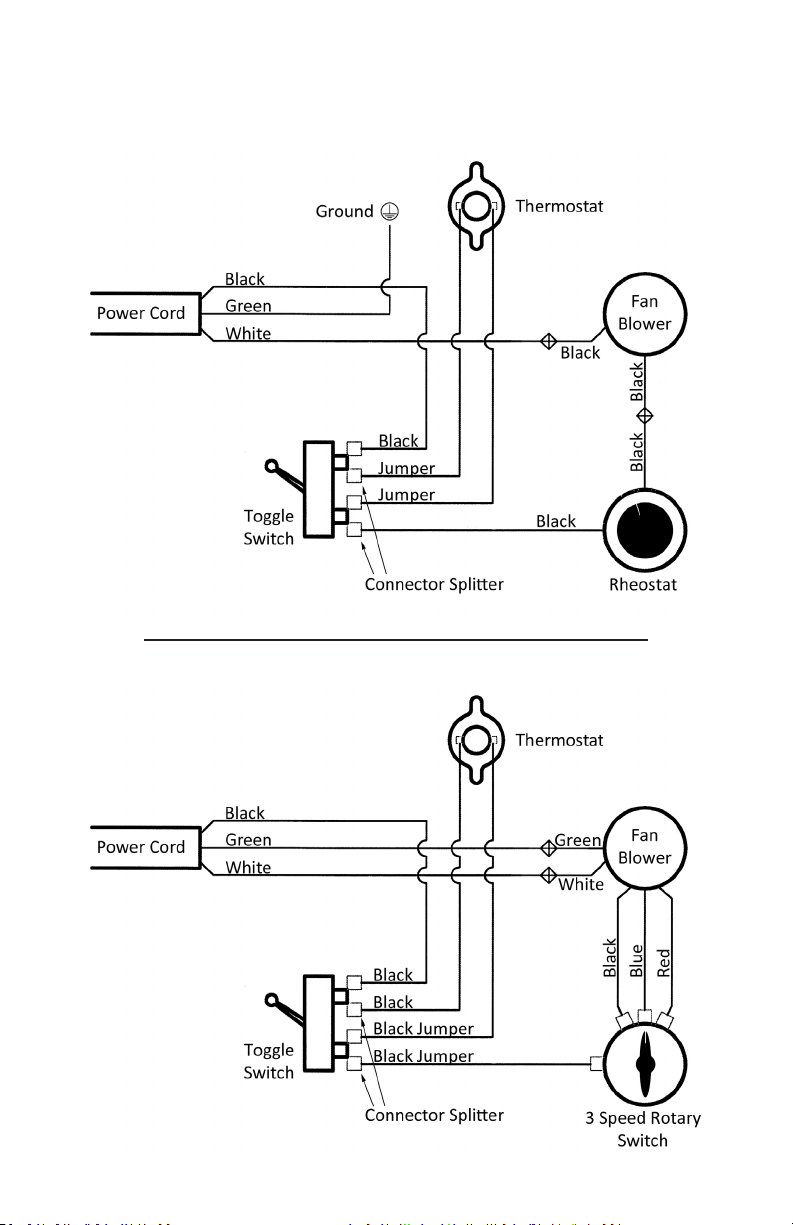
Connect the two wires from the blower to the wires on the stove.
Replace the magnec blower cover and begin using the stove.